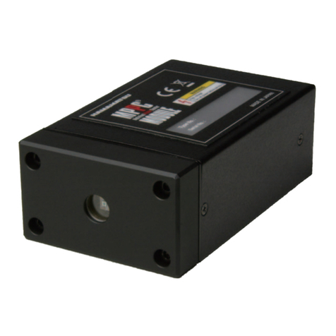
Hamamatsu UVTRON Operating instructions

TECHNICAL INFORMATION
How to Use UVTRON®

2
FEATURES
Capable of detecting very weak ultraviolet light (down to 1 pW)
z
Insensitive to visible and infrared light (solar blind characteristics)
z
High reliability and long life (over 10,000 hours of continual discharge operation)
z
High-speed response (less than a few milliseconds)
z
Low current operation
z
Miniature size and lightweight
z
APPLICATIONS
Combustion monitors for gas/oil burner
z
Fire alarms
z
Arson surveillance sensors
z
Flame detectors for gas/oil lighters and matches
z
Detection of ultraviolet light leakage
z
Detection of discharge phenomenon
z
Figure 1 shows typical spectral radiant intensity of a gas burner ame (city gas), tungsten lamp, and the sunlight on
the earth’s surface, along with UVTRON spectral response characteristics. As this gure shows, the UVTRON has no
sensitivity in the visible range and is only sensitive to ultraviolet light in a very narrow region of spectrum.
TPT B0009EB
200 300 400 500 600 700 800 900
100
100
50
0
IR REGIONVISIBLE REGIONUV REGION
WAVELENGTH (nm)
TUNGSTEN
LAMP
GAS
FLAME
SUNLIGHT
UVTRON
SPECTRAL
RESPONSE
RELATIVE SENSITIVITY, RELATIVE INTENSITY (%)
Various Types of Spectral Radiant Intensity
TPT B0009EB
Figure 1: Typical Spectral Radiant Intensity
The UVTRON is a sensor sensitive only to ultraviolet light with wavelengths shorter than 260 nm. Featuring high
sensitivity high output, and high-speed response, the UVTRON is the ideal sensor for detecting ame and electrical
discharge phenomena.

3
STRUCTURE AND BASIC OPERATING PRINCIPLES
The UVTRON is a bipolar tube with a structure similar to that of a phototube. Just as with phototubes, the UVTRON
utilizes the photoelectric emission effect, but the inside of the UVTRON tube is lled with special a gas rather than be-
ing a vacuum, so it operates as a discharge tube. Figure 2 shows its structure and a schematic diagram of operation. A
voltage is applied across the anode and photocathode (cathode) which is only sensitive to ultraviolet light. When UV
light passing through the UV glass (UVTRON bulb) strikes the cathode, photoelectrons (electrons) are emitted from the
cathode surface due to the photoelectric emission effect. These photoelectrons are then drawn to the anode by the elec-
trical eld created by the supply voltage. If the supply voltage is low, the operation is the same as for a phototube and
the current, i, is extremely weak. When the voltage is increased to strengthen the electrical eld, the photoelectrons are
accelerated so they collide with the gas molecules within the tube and ionize them. The electrons produced by ionization
continue to collide with other gas molecules while causing ionization until they nally reach the anode. Meanwhile, the
positive ions are accelerated towards the cathode and the resulting collisions with the cathode generate a great number
of secondary electrons. As this cycle is repeated, a large current suddenly ows between the anode and cathode, creating
an electrical discharge. This phenomenon is called gas multiplication and the voltage at which this discharge starts is
called the discharge starting voltage Vl of the UVTRON.
Once the electrical discharge has begun, the tube is lled with electrons and ions and the voltage that maintains the
discharge drops to a low value. This value is called the discharge sustaining voltage Vs. Figure 3 shows this state. The
UVTRON primarily operates in the glow discharge region, but in this region, since the discharge sustaining voltage Vs
is lower than the discharge starting voltage Vl, the discharge will continue unless some means is employed to control
the supply voltage.
TPT C0010EA
TPT C0010EA
+–
i
R
HIGH VOLTAGE Ebb
DISCHARGE
CURRENT
TUBE VOLTAGE V
CURRENT LIMITING
RESISTANCE
PHOTO-
ELECTRONS
ELECTRONS
FROM IONIZATION
CATHOD
(PHOTOCATHODE)
UV LIGHT
FILLED GAS
UV GLASS
ANODE
Schematic Diagram of UVtron Operation
Figure 2: Schematic of UVTRON Operation
TPT B0029EA
TPT B0029EA
10-6 10-4 10-2 1102
Ebb
VL
VS
DISCHARGE CURRENT i (A)
GLOW DISCHARGE REGION
OPERATION
POINT
Rs LOAD LINE
TUBE VOLTAGE (V)
UVtron V-I Characteristics
Figure 3: UVTRON Voltage-Current Characteristics

4
UVtron DRIVE CIRCUIT
Operating a UVTRON requires a high voltage of about 350 V. Figure 4 shows the basic circuit for the DC-DC con-
verter high-voltage power supply and the operating waveforms for each part. In this case, it is important to lower the
converter oscillation frequency, f, to reduce the capacitance of capacitor C1 for smoothing the rectied high voltage, and
to raise the power supply output impedance. Here is an explanation of the operation of this circuit. (See Figures 4-1 and
4-2.)
Point (a): This is the converter oscillation waveform. Pulses with a width of a few microseconds are generated at in-
tervals of a few milliseconds to a few tens of milliseconds.
Point (b): The height of pulses is raised in proportion to the winding ratio for the step-up transformer.
Point (c): High DC voltage Ebb is supplied to the UVTRON's anode by rectier diode D and smoothing capacitor C1.
Point (d): Discharge starts when ultraviolet light enters the UVTRON. The charge on C1 begins to ow as discharge
current, i, to generate narrow voltage pulses across R and C2.
Point (e): The charge on C1 is exhausted, the anode voltage falls below the discharge sustaining voltage Vs, and the
discharge stops. The anode voltage does not recover until the next charge. During that period, the ions in
the UVTRON are quenched.
Point (f): If no ultraviolet light enters the UVTRON, the anode voltage recovers to Ebb, and there is no discharge un-
til ultraviolet light is received.
The UVTRON repeats this cycle to indicate the presence or absence of ultraviolet light with pulse signal output.
Here, it is important that the converter oscillation interval (l /the oscillation frequency f) be greater than the time re-
quired for the ions generated in the UVTRON tube by the discharge to be quenched, so this interval must be from 5 to l0
milliseconds. This period is called the quenching time. Also, since the capacitance of smoothing capacitor C1 inuences
the discharge current, it is best to reduce the capacitance of C1in order to retard the wear on the electrodes and to reduce
the number of ions generated. The optimum capacitance is a few tens of picofarads.
i
+
–
V1
D
Tr
C1
C2R
UV TRON
A
UV
K
(a)
(c)(b)
(d)
TPT C0011EA
TPT C0011EA
UVTRON OUTPUT
WAVEFORM
OSCILLATION
WAVEFORM
OSCILLATOR
CIRCUIT
UVtron Drive Circuit
Figure 4-1: UVTRON Drive Circuit

5
T1
T2
T3
V2
(d)
(c)
(a)
(b)
(e)
(f)
Vs
V1
Ebb
Ebb
0 V
0 V
0 V
0 V
f=1/T1
TPT C0012EA
TPT C0012EA
DISCHARGE
SUSTAINING VOLTAGE
INCIDENCE OF UV LIGHT
UVTRON
OUTPUT WAVEFORM
UVTRON
ANODE VOLTAGE
STEP-UP TRANSFORMER
VOLTAGE WAVEFORM
DC-DC CONVERTER
OSCILLATION WAVEFORM
UVtron Operation Waveforms
Figure 4-2: UVTRON Operation Waveforms
SIGNAL PULSES AND BACKGROUND
When the UVTRON is operated with the circuit shown in Figure 4-1, the number of output pulses is increased in
proportion to the incident light intensity at low light levels. However, it will be saturated at the converter oscillation fre-
quency f, as shown in Figures 5 and 6. Because of these characteristics, the UVTRON is better suited for on-off opera-
tion that determines whether or not ultraviolet light is present, rather than for precise measurement of light level.
The next point that must be considered is the background (BG). The BG is caused by sporadic discharges that occur
due to radiation such as cosmic rays and static electricity, even if no ultraviolet light enters the UVTRON. Figure 6 also
shows this phenomenon. When detecting ultraviolet light with the UVTRON, the BG causes false operation if the output
pulses are directly used as the detection signals. Therefore, the signal must be processed to cancel out this background.
Figure 6: UVTRON Output Pulses
Figure 5: UVTRON Sensitivity and Background
010-14
100
(BG)
101
102
103
10-13 10-12 10-11
λ: 200 nm
1200/min.
TPT B0030EA
TPT B0030EA
INCIDENT LIGHT INTENSITY (W/cm2)
LIGHT LEVEL EQUIVALENT TO
LIGHTER FLAME (25 mm) AT 5 m
(SATURATION)
STANDARD TYPE
HIGH SENSITIVITY
TYPE
DC=DC CONVERTER
f=20 Hz
UVtron OUTPUT PULSE (min-1)
UVtron Sensitivity and Background
10 s to 1000 s
0.2 s to 1 s
50 ms
TPT C0013EA
TPT C0013EA
RANDOM
LOW LIGHT LEVEL
Ex.: Lighter flame
(25 mm)
at 5 m away
NO UV LIGHT
(BG)
UVtron Output Pulses
SATURATION
LIGHT LEVEL
DC-DC CONVERTER
f=20 Hz

6
SIGNAL PROCESSING CIRCUIT
Since the UVTRON output pulse waveforms are the same for incident ultraviolet light and for background noise, the
waveforms cannot be distinguished. Therefore, the pulse generation frequency (interval between pulses) is used to can-
cel out the BG. Figure 7 is a block diagram for the signal processing circuit and Figure 8 is a timing chart for its opera-
tion. The operation of this circuit is explained below.
Point (a): The output pulses from the UVTRON are input to the gate timer and the counter at the same time. The
counter counts the pulses sequentially.
Point (b): The gate timer maintains the open state as long as the pulses enter in succession at time intervals shorter
than the setting time T1. When the pulse interval is greater than T1, the gate timer closes the gate and resets
the counter.
Point (c): When a series of pulses are input, the counter adds them up. When the number of pulses reaches the setting
value, a pulse is generated to the output circuit and the counter is reset.
Point (d): At the output circuit, the output pulses from the counter are lengthened to the necessary time interval (T2)
and are output.
*1 (Figure 8): The setting time T1 must be shorter than the interval at which background noise pulses are generated. It is
usually safe to set T1 to 5 seconds or less. If set too short, weak ultraviolet light cannot be detected.
*2 (Figure 8): The sensitivity of the device can be adjusted by the counter setting. To trigger the device with weak ultravio-
let light, set the counter to 10 or less. To have the device only detect higher intensity of ultraviolet light, or
to have the device operate for weak ultraviolet light if it is received for a long period of time, set the counter
value to more than 10. If the counter value is set to 3 or less, the BG may not be cancelled out, so use caution.
Q
5 V
5 V
GND
GND
–
Q
Q
–
Q
10 µs
10 V
0 V
T2(10 ms)
(d)
(a)
(c)
(b)
1000 pF 10 k
TPT C0014EA
TPT C0014EA
UVTRON
CATHODE
UVTRON OUTPUT PULSE
GATE TIMER
RESET
OPERATION SENSITIVITY
SETTING SWITCH
COUNTER
OUTPUT SIGNAL
WAVEFORM
OUTPUT
CIRCUIT
Signal Processing Circuit
Ω
Figure 7: Signal Processing Circuit

7
10 µs
T1(2 s) *1
*2
2 s 2 s
3
22
1111
000
0
(c)
(b)
(a)
1 µs or less
10 ms
TPT C0015EA
TPT C0015EA
SIGNAL OUTPUT Q
COUNTER LEVEL
PATTERN
COUNTER
RESET
UVTRON
OUTPUT PULSE
GATE TIMER
(Ex.) When 3 pulses enter in succession within an interval
of 2 seconds, a pulse with a width of 10 ms is output
as the signal output.
Operation Time Chart for Signal Processing Circuit
Figure 8: Operation Time Chart for Signal Processing Circuit
SUPPLY VOLTAGE AND SENSITIVITY
Figure 9 shows a typical relation between the supply voltage and the UVTRON sensitivity. The UVTRON is more
sensitive as the supply voltage is increased, but this also increases the background noise. Keep the supply voltage within
the recommended range.
-10 %
0
50
100
150
200
+10 %
TPT B0031EA
TPT B0031EA
CHANGE IN SUPPLY VOLTAGE
(Recommended Value)
RELATIVE SENSITIVITY (%)
Supply Voltage and Sensitivity
Figure 9: Supply Voltage and Sensitivity

WEB SITE www.hamamatsu.com
Information in this manual is current as of Oct. 2008. Specifications are subject to change without notice due to product improvement, etc.
For the latest information, please contact us at the address below.
HAMAMATSU PHOTONICS K. K., Electron Tube Division
314-5, Shimokanzo, Iwata City, Shizuoka Pref., 438-0193, Japan, Telephone: (81)539/62-5248, Fax: (81)539/62-2205
U.S.A.: Hamamatsu Corporation: 360 Foothill Road, P. O. Box 6910, Bridgewater, N.J. 08807-0910, U.S.A., Telephone: (1)908-231-0960, Fax: (1)908-231-1218, E-mail: [email protected]
Germany: Hamamatsu Photonics Deutschland GmbH: Arzbergerstr. 10, D-82211 Herrsching am Ammersee, Germany, Telephone: (49)8152-375-0, Fax: (49)8152-2658, E-mail: info@hamamatsu.de
France: Hamamatsu Photonics France S.A.R.L., 19, Rue du Saule Trapu, Parc du Moulin de Massy, 91882 Massy Cedex, France, Te lephone: (33)1 69 53 71 00, Fax: (33)1 69 53 71 10, E-mail: info[email protected]
United Kingdom: Hamamatsu Photonics UK Limited: 2 Howard Court, 10 Tewin Road, Welwyn Garden City, Hertfordshire AL7 1BW, United Kingdom, Te lephone: 44-(0)1707-294888, Fax: 44-(0)1707-325777, E-mail: info@hamamatsu.co.uk
North Europe: Hamamatsu Photonics Norden AB: Smidesvagän 12, SE-171-41 SOLNA, Sweden, Te lephone: (46)8-509-031-00, Fax: (46)8-509-031-01, E-mail: info@hamamatsu.se
Italy: Hamamatsu Photonics Italia S.R.L.: Strada della Moia, 1/E 20020 Arese (Milano), Italy, Telephone: (39)02-935 81 733, Fax: (39)02-935 81 741, E-mail: info@hamamatsu.it
TPT 9001E02
JAN. 2009WD
PRECAUTIONS WHEN USING THE UVTRON
(1) Installation
When the UVTRON discharges, it emits ultraviolet radiation. If two or more UVTRONs are used in close
proximity, they must be arranged so that they will not interfere with each other optically.
(2) Humidity
Humidity around the UVTRON leads may cause leak current, dropping the anode voltage and stopping the
UVTRON from operating. In particular, if dirt or dust gets on the leads, it easily absorbs moisture, so keep the area
around the leads clean.
(3) Dirt on the window
Since the UVTRON operates at high voltage, static electricity causes dust to build up on the surface of the glass
bulb. This will lower the ultraviolet transmittance and UVTRON sensitivity, so periodic inspection and mainte-
nance is necessary, such as wiping off with gauze moistened with alcohol.
(4) Soldering
When mounting the UVTRON on a printed circuit board, solder the leads quickly (soldering iron tip temperature:
350°C for less than 5 seconds). If the leads are heated excessively, the glass may crack or the UVTRON
characteristics deteriorate. After soldering, wipe away the solder ux with alcohol, etc. The ux residue absorbs
moisture which may cause current leak, dropping the UVTRON supply voltage and stopping the operation. When
using a UVTRON with hard pins, use the mating sockets available from Hamamatsu Photonics.
(5) Vibration and shock
The UVTRON is designed to pass vibration and shock tests in compliance with IEC 60068-2-6 (sinusoidal
vibration test – R9454, R9533: 3.0 mm peak to peak, 200 m/s2,10 Hz to 2000 Hz; other types: 1.5 mm peak to
peak, 100 m/s2, 10 to 500 Hz) and IEC 60068-2-27 (shock test - R9454, R9533: 10000 m/s2, 1 ms; other types:
1000 m/s2, 11 ms). However, if the UVTRON is subjected to excessive shock such as dropping, the glass bulb may
crack or the internal electrode may be deformed, resulting in poor electrical characteristics. So use extreme caution
when handling the UVTRON.
(6) Polarity
The UVTRON has a cathode and an anode, so connect them with correct polarity. Reverse polarity connection
causes malfunction or breakdown.
Table of contents
Other Hamamatsu Security Sensor manuals
Popular Security Sensor manuals by other brands

Trilite
Trilite SG10-12RG installation instructions

jablotron
jablotron JA-87P quick start guide

PCB Piezotronics
PCB Piezotronics 352A25/NC Installation and operating manual

Solid Signal
Solid Signal CDLRC user manual

Acorn Safety
Acorn Safety S1320-BF Installation, operation and maintenance instructions

DADISICK
DADISICK QT Series user manual

Spectrex
Spectrex SharpEye 40/40 Series quick start guide

Fireye
Fireye FLAME SIGNATURE SCANNER 1000 manual

BUCKINGHAM MFG
BUCKINGHAM MFG 400000 BuckSorber Series Instructions & warnings

Weco
Weco 03.G5.PWS.KAP.110 user manual

Rielta
Rielta STEKLO-3 installation guide

Optex
Optex WX Shield Series installation instructions