Hammond XPK-200 User manual

Model :2-
*#1 *#1
*#1 *#1
*#1
Owner’s Manual
Thank you, and congratulations on your choice of a
Hammond XPK-200.
The XPK-200 is a 20-note MIDI Pedalboard.
In order to get the most out of this instrument for many
years to come, please take the time to read this manual in
full.
*#1 :2-Owner’s Manual
2
Before using this unit, please carefully read these “Safety Instructions”.
Please be sure to keep this manual at hand for future reference.
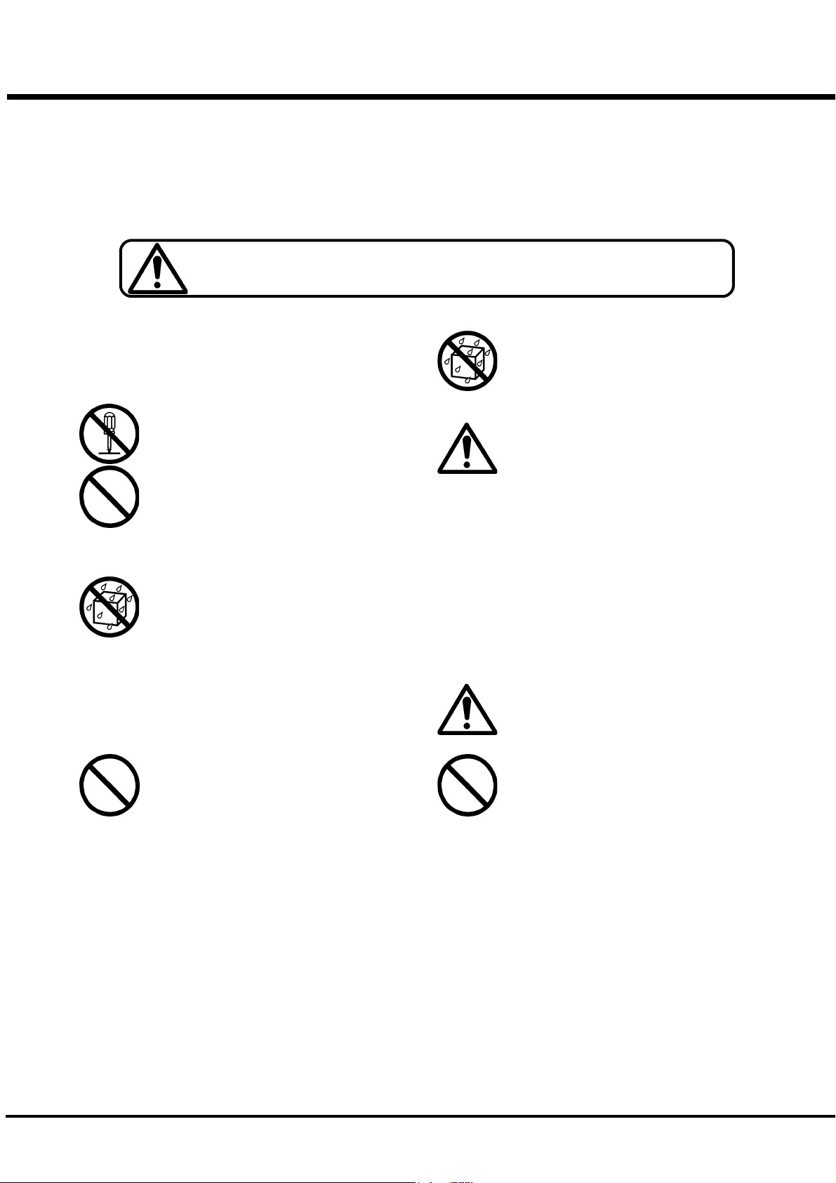
This “Safety Instruction” section contains very important points for securing your safety.
WARNING This sign shows there is a risk of death or severe injury if this unit is not properly used
as instructed.
Follow instructions:
All operation and user instructions should be fol-
lowed.
Do Not Disassemble:
Do not disassemble this unit.
Servicing:
The user should not attempt to service the appliance
beyond that is described in the Operation Instruc-
tions. All other servicing should be referred to quali-
fied service personnel.
Location:
Using the unit in the following locations can result
in a malfunction.
In direct sunlight
Locations of extreme temperature or hu-
midity
Excessively dusty or dirty locations
Locations of excessive vibration
Close to magnetic fields
Placement:
Do not place on a non-stable stand or a listing place.
Set on a stable horizontally place.
Object and Liquid Entry:
Care should be taken so that objects do not fall and
liquids are not spilled into the enclosure through the
openings.
Damage Requiring Service:
The appliance should be serviced by qualified ser-
vice personnel when:
The power supply cord or the plug has been
damaged; or
Objects have fallen, or liquid has been
spilled into the appliance; or
The appliance has been exposed to rain; or
The appliance does not appear to operate
normally or exhibits a marked change in
performance; or
The appliance has been dropped, or the
enclosure damaged.
Children:
If you let your children use this unit, please always
watch and guide them and do not leave them alone.
Do Not Cause a Shock
Do not drop or cause a shock to this unit.
IMPORTANT SAFETY NOTICE

*#1 :2-Owner’s Manual
3
CAUTION
This sign shows that there is a risk of injury or material damage if this unit is not
properly used as instructed.
*Material damage here means damage to the room, furniture or animals or pets.
Keep Away from Extreme Heat:
Do not use, leave or store this unit in an automobile
or near heating apparatuses that emit extreme heat.
This may cause deformation or damages to this unit.
Stack/Ride:
Do not stack heavy devices or sit on this unit. This
may cause personal injuries.
Detach the Expression Pedal, Connec-
tion Cables, etc. before moving:
Before you move/transport this unit, detach the
Expression Pedal and all the connection cables. Oth-
erwise, the cables maybe damaged which may cause
fire or electrical shock.
Do Not Pull the AC adaptor Cord:
Be sure to grasp the AC adaptor when unplugging it
from a wall outlet. Pulling on the power cord can
damage it, and create the danger of fire and electri-
cal shock.
Handling Cables:
Do not entangle the cables. Always keep them away
from children’s reach.
Care:
If the exterior becomes dirty, wipe it with a clean,
dry cloth. Do not use liquid cleaners such as ben-
zene or thinner, or cleaning compounds or flammable
polishes.
Hook Up:
Turn off all devices before hook up.
Follow all instructions and use only designated
cables.
Movable Parts:
Be careful not to pinch your fingers when you as-
semble or disassemble this unit.

*#1 :2-Owner’s Manual
4
1. Pedal keyboard
20-note non-velocity pedal keyboard.
2. Expression Bracket 1
This bracket is a base for mounting the optional Expression
Pedal EXP-100F or V-20R.
3. LED
This LED dimly lights when the power is ON. It also indi-
cates the playing status of the pedal keyboard (lights up when
being played) and the MIDI channel.
4. Cord Hook
Hook the AC Adaptor Cord or the DCC-2 Cable on this to
provide a strain relief.
5. DC IN Jack
This jack connects the attached AC Adaptor AD1-1508 (or
AD3-1508) or DCC-2 Cable.
6. MIDI IN 1 Jack
This is a MIDI input Jack. MIDI signals received at this in-
put will be merged with the playing information of the
Pedalboard and sent out the MIDI OUT jack.
7. MIDI IN 2 Jack
This is also a MIDI input Jack. MIDI signals received at this
input will be merged with the playing information from MIDI
IN 1 and the playing information of the Pedalboard and sent
out the MIDI OUT jack.
8. MIDI OUT Jack
This jack sends out the playing information of the Pedalboard
as well as any merged informaition from MIDI IN 1 or 2.
9. M4 x 5 Screw (2)
Use these screws for attaching the Expression Pedal EXP-
100F to Expression Bracket 1.
10. ø4 x 8 Screw (2)
Use these screws for attaching the Bracket Spacer.
11. Bracket Spacer
12. Expression Bracket 2
These (11 and 12) are used together with the Expression
Bracket 1 for attaching the Expression Pedal V-20R.
NAMES AND FUNCTIONS
2
1
3
4 5 7 86 910 11 12

*#1 :2-Owner’s Manual
5
MOUNTING THE EXPRESSION PEDAL
Mounting the EXP-100F Mounting the V-20R
By use of a #2 Phillips screwdriver, temporarily remove the
screw as shown from the bottom of the EXP-100F. Place the
EXP-100F on top of the Expression Bracket 1. Fasten the
EXP-100F to the front of the bracket as shown using the 2 -
M4 x 5mm screws supplied. Using the screw that you previ-
ously removed, fasten the EXP-100F to the bottom of the
bracket as shown.
Place the Expression Bracket 1 on top of the XPK-200 as
shown. Fasten the Bracket to the XPK-200 by turning the 2
knob bolts supplied clockwise.
Place the Expression Bracket 1 on top of the XPK-200 as
shown. Fasten the Bracket to the XPK-200 by turning clock-
wise the 2 knob bolts supplied.
Place the V-20R on top of the Expression Bracket 1 and route
the cord through the read hole in the Bracket as shown. Place
the Bracket Spacer on the Expression Bracket 1 as shown
and fasten the spacer to the bracket with a #2 Phillips screw-
driver and 2 - ø4 x 8mm screws.
Fasten the V-20R to the Expression Bracket 1 by sliding the
Expression Bracket 2 onto the Expession Pedal assembly as
shown and turning clockwith the knob bolt supplied.
attached
EXP-100F
M4 x 5 screws
*#1 :2-Owner’s Manual
6
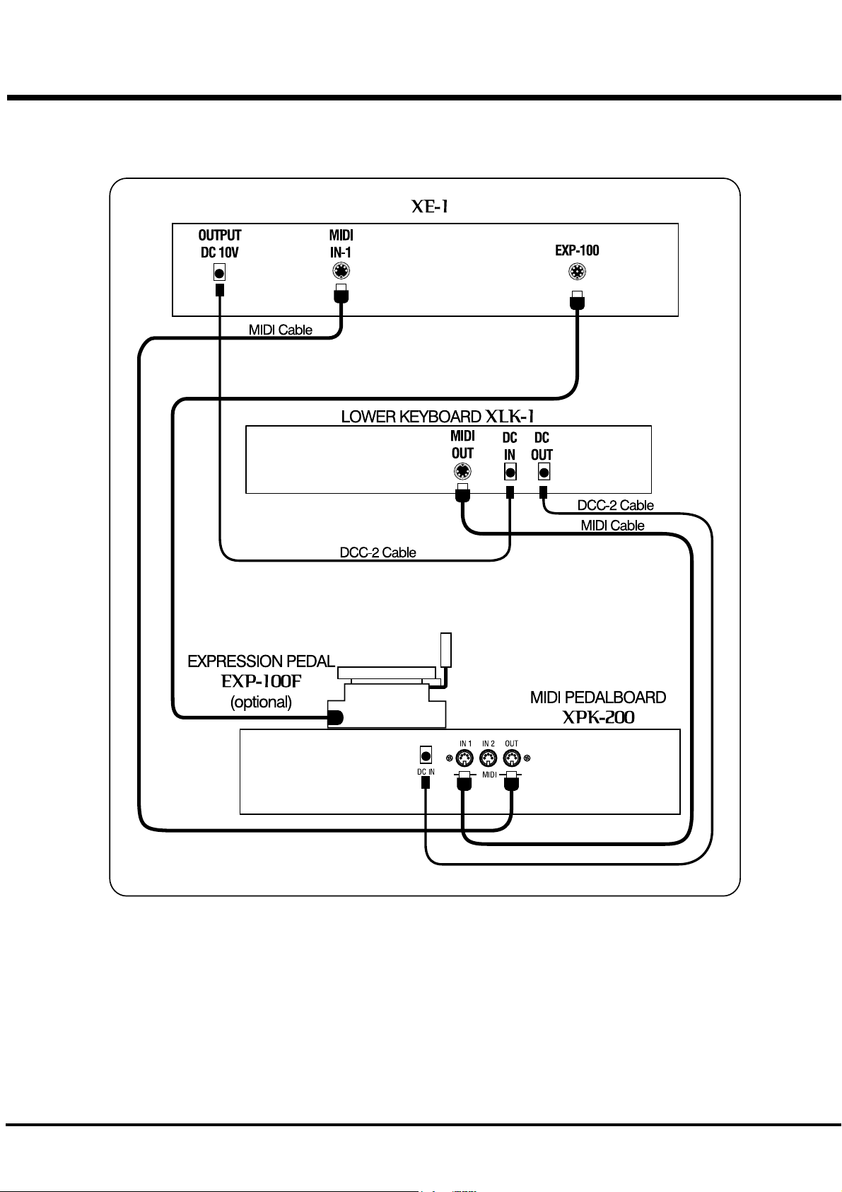
An example of the Hook-up of the XE-1 and XLK-1
Connect the MIDI OUT of the XLK-1 to the MIDI IN 1 of this unit by means of a MIDI cable.
Connect the MIDI OUT of this unit to the MIDI IN 1 of the XE-1 by means of a MIDI cable.
Connect the DC IN of this unit to the DC OUT of the XE-1 using the DCC-2 cable attached to the
XLK-1. The AC adaptor is not used required for this hook-up.
The playing information from the XLK-1 that’s received at the MIDI IN 1 Jack on this unit is then
merged with the playing information of this unit, and sent out of the MIDI OUT Jack on this unit.
The power switch on the XE-1 switches the power on/off on this unit.
HOOK-UP

*#1 :2-Owner’s Manual
7
A Hook-up example of the XK-3 and the XLK-3
Connect the MIDI OUT on this unit to the MIDI IN (PEDAL) of the XK-3 by means of a MIDI
cable.
Connect the AC adaptor AD1-1508/AD3-1508 to the DC IN on this unit.
The power on this unit is not turned “On” or “Off” with the XK-3. Pull out the AC adaptor from the
AC outlet after each use.

*#1 :2-Owner’s Manual
8SETTING
A setting example of the XE-1
Switch ON the power of
the XE-1. The PLAY mode is displayed on the LCD.
Touch the [MIDI] button.
Select SINGLE or DOUBLE according to the number of manuals
that you are using.
Touch the Select Button 14 to set this setting.
Touch the [PLAY] button and return to the PLAY mode.
This completes the setting.
This setting is memorized, even
after the power is switched off.
*#1 :2-Owner’s Manual
9
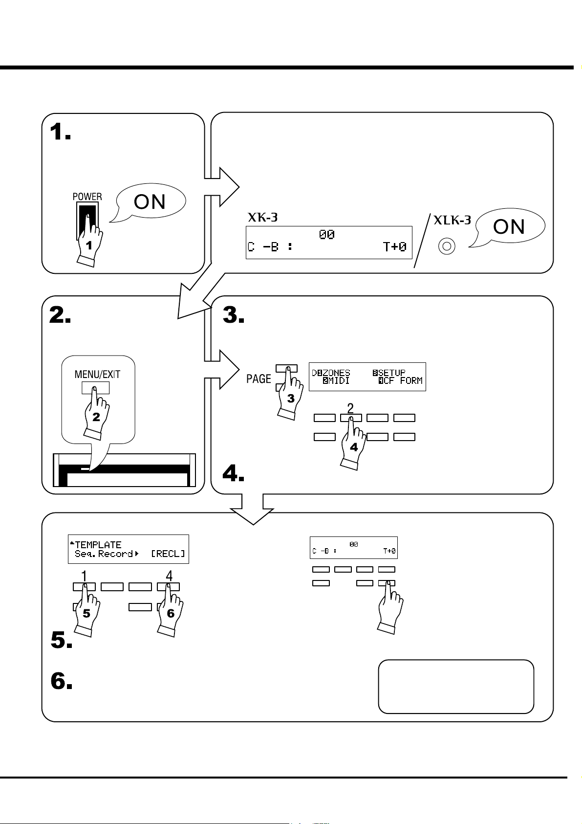
A setting example of the XK-3
Switch ON the power of
the XK-3.
PLAY mode is displayed on the LCD.
The light on the XLK-3 will also be turned ON when the XLK-3 is
connected.
Touch the [MENU/EXIT] button.
Touch the [PAGE] button and move to Page D.
Touch the [2] MIDI button.
Select “Seq.Record”.
Touch the [4] RECL button.
Touch the [PLAY] button to
return to the PLAY mode.
This completes the setting.
This setting is memorized, even
after the power is switched off.
*#1 :2-Owner’s Manual
10 MIDI CHANNEL, MERGE
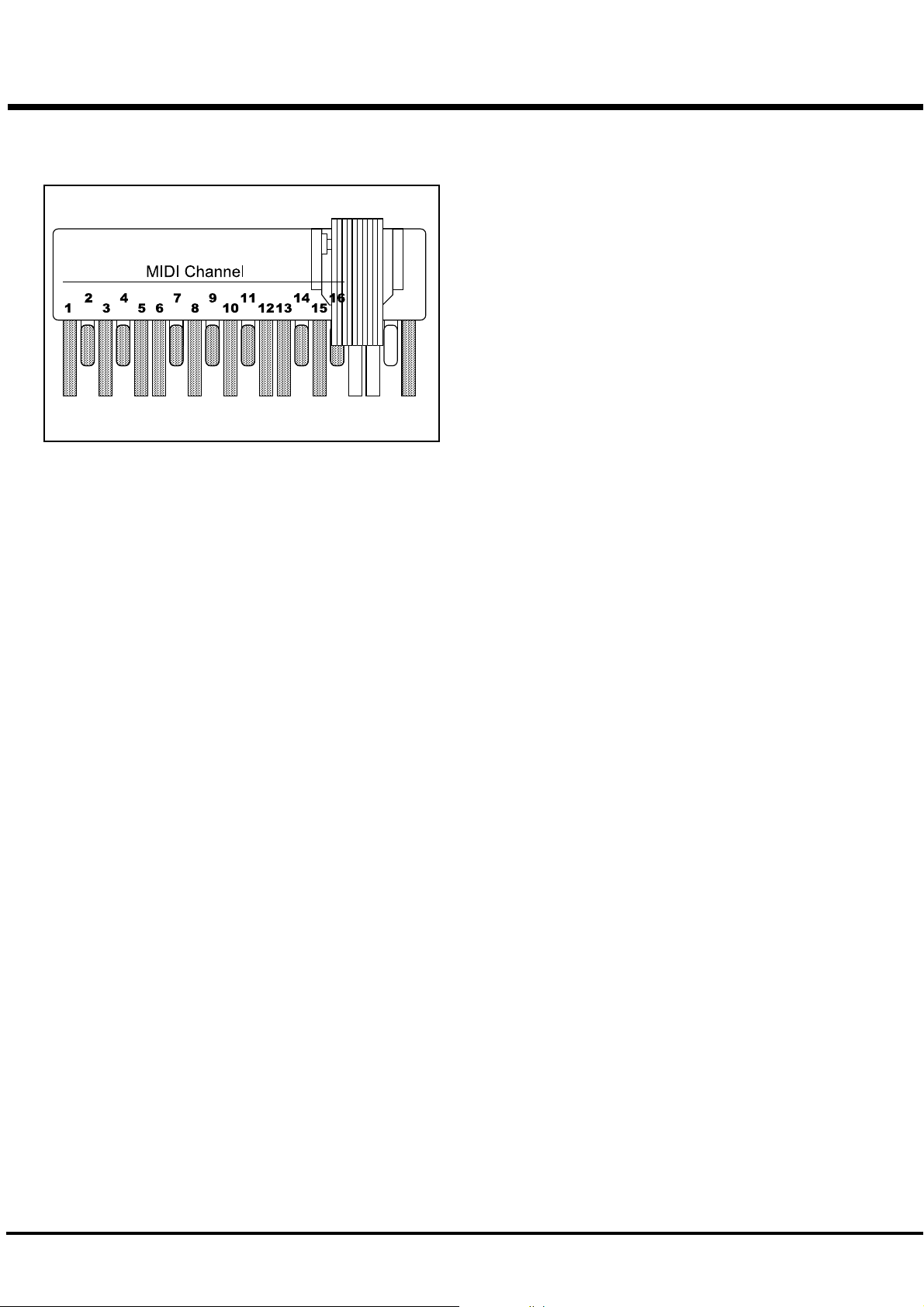
Setting the MIDI channel
Important Notes on MIDI Merge
The factory default setting for the Pedalboard is channel 3.
If you want to change it follow the procedure below:
Start with the power turned off. Turn on the power while
holding down the highest G pedal and the pedal correspond-
ing with the MIDI channel. (See the illustration on the left.)
The LED light on this unit will blink the same number of
times as the number of the MIDI channel selected. The set-
ting is memorized and will remain in memory even if the
power is turned off.
This unit is equipped with the MIDI merge function. This feature allows MIDI playing
information received at the MIDI IN jacks to be merged (blended) with the MIDI infor-
mation from the Pedalboard and sent out the MIDI out jack.
PLEASE NOTE several points regarding this feature.
The MIDI messages to be merged
The MIDI merge function of this Pedalboard will only merge the channel messages. It
does not merge such system message as system exclusive messages or MIDI clock.
Duplication of the MIDI channel
The Channels assigned to the MIDI INs must be different than the channel of the
Pedalboard in order to provide proper music parts to the host keyboard.
The MIDI loop
If the MIDI information sent out of the MIDI OUT Jack of this Pedalboard returns to the
MIDI in jack, a MIDI information loop happens and this causes a malfunction.
If the MIDI IN/OUT of this unit and those of the external equipment are connected, set
the echo-back (MIDI thru) function or the local control function to correct the problem.

*#1 :2-Owner’s Manual
11
MIDI IMPLEMENTATION
[Hammond MIDI Pedalboard] Date: 4-Apr-2006
Model: XPK-200 Version: 1.0
Default 3X
Changed 1 - 16
Default 3X
Messages XX
Altered ***** X
36 - 55 X
: True Voice *****
Note ON XX
Note OFF XX
After Key's XX
Touch Ch's XX
Pitch Bender XX
XX
XX
: True # ***** X
System Exclusive XX
: Song Position XX
: Song Select XX
: Tune XX
: Clock XX
: Commands XX
: Local On/Off XX
: All Notes Off XX
: Active Sense OX
: Reset XX
Mode 1: OMNI ON, POLY Mode 2: OMNI ON, MONO O: Yes
Mode 3: OMNI OFF, POLY Mode 4: OMNI OFF, MONO X: No
MIDI Implementation Chart
Function
Program
Change
System
Common
Transmitted Recognized Remarks
Basic
Channel
System
Real Time
Aux
Messages
Mode
Note
Number
Velocity
Control
Change

*#1 :2-Owner’s Manual
12
Printed in Japan
00457-40141
V1.00-060926
SPECIFICATIONS
SERVICE
Hammond maintains a policy of continuously improving and upgrading its instruments and therefore reserves the right to
change specifications without notice. Although every attempt has been made to insure the accuracy of the descriptive
contents of this Manual, total accuracy cannot be guaranteed.
Should the owner require further assistance, inquiries should first be made to your Authorized Hammond Dealer. If you
still need further assistance, contact Hammond at the following addresses:
Technical materials are available and can be obtained by mailing a request to the appropriate address listed above marked
ATTENTION: SERVICE DEPARTMENT.
Manufacturer:
SUZUKI MUSICAL INSTRUMENT MFG. CO., Ltd.
25-12, Ryoke 2 Chome
Hamamatsu 430-0852 (Shizuoka)
JAPAN
In the United States contact:
HAMMOND SUZUKI USA, Inc.
733 Annoreno Dr.
Addison, IL 60101
UNITED STATES
In Europe contact:
HAMMOND SUZUKI EUROPE
B.V.
IR. D.S. Tuynmanweg 4A
4131 PN Vianen
THE NETHERLANDS
All other countries contact:
HAMMOND SUZUKI Ltd.
25-11, Ryoke 2 Chome
Hamamatsu 430-0852
(Shizuoka)
JAPAN
Website:
www.hammondorganco.com
E-mail: [email protected]
Website: www.hammondsuzuki.com
Website: www.suzuki-music.co.jp
Keyboard
20 notes non-velocity
Connections
DC IN
MIDI OUT
MIDI IN 1
MIDI IN 2
Dimension
872(W) x 400(D) x 133(H) mm
34.3(W) x 15.7(D) x 5.2(H) inch
Weight
13.5kg
29.8lbs
Accessory
AC Adaptor
AD1-1508 (100 - 120V)
AD3-1508 (220 - 240V)
Expression Bracket 1
Expression Bracket 2
Bracket Spacer
MIDI Cable (2.0m)
Screw M4 x 5mm (2pcs)
Screw ø4 x 8mm (2pcs)
Other manuals for XPK-200
1
Table of contents
Other Hammond Music Pedal manuals


