Making the Electrical
Connections
WARNING: To avoid possible electrical
shock, be sure electricity is turned off at
the main fusebox before wiring.
NOTE: (Fig. 8) This remote control unit is
equipped with 16 code combinations to
prevent possible interference from or to
other remote units. The frequency switches
on your receiver and wall transmitter have
been pre-set from the factory. Please
recheck to make sure the switches from
both units areset to the same positions.Any
combination of settings will operate thefan
as long as the wall transmitter and receiver
are set tothe same switchsettings.
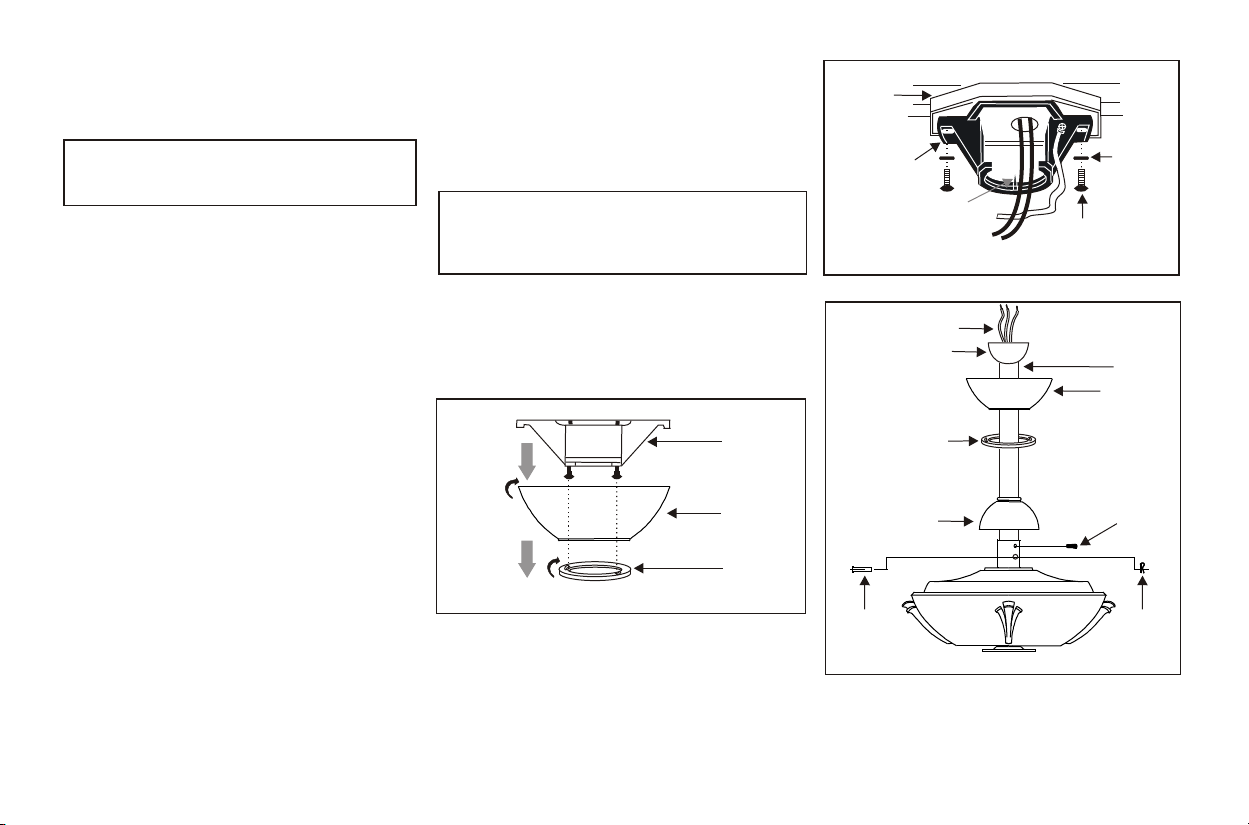
Step 1. (Fig. 9) Insert the receiver unit into
the hanger bracket with the flat side of the
receiver facing theceiling.
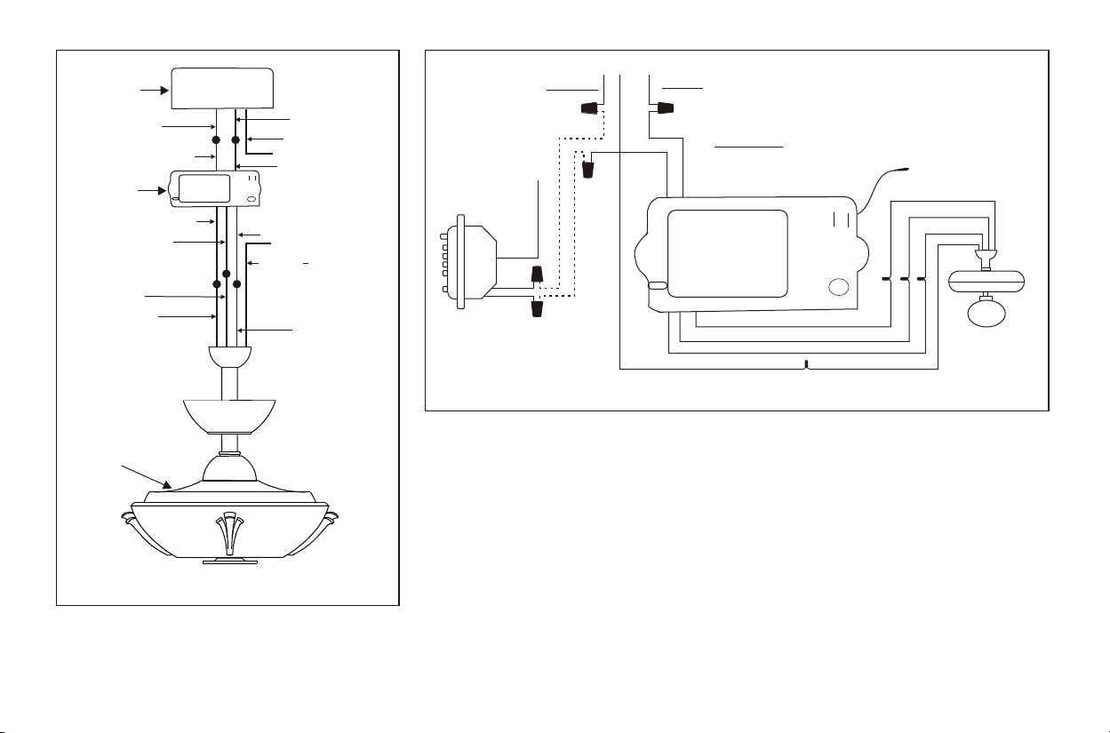
Step 2. (Fig. 10 & 11) Motor to receiver
Electrical Connections; Connect the Black
wire from the fan to the Black wire marked
"To Motor L" from the receiver. Connect
the White wire from the fan to the White
wire marked "To Motor N" from the
receiver. Connect the Blue wire from the
fan to the Blue wire marked "For Light"
from the receiver.
Step 3. (Fig. 10 & 11) Receiver to house
supply wires Electrical Connections;
Connect the Black (Hot) wire from the
outlet box to the Black wire marked "AC
in L" from the receiver. Connect the White
(neutral) wire from the outlet box to the
white wire marked "AC in N" from the
receiver. Secure all wire connections with
the plastic wirenuts provided.
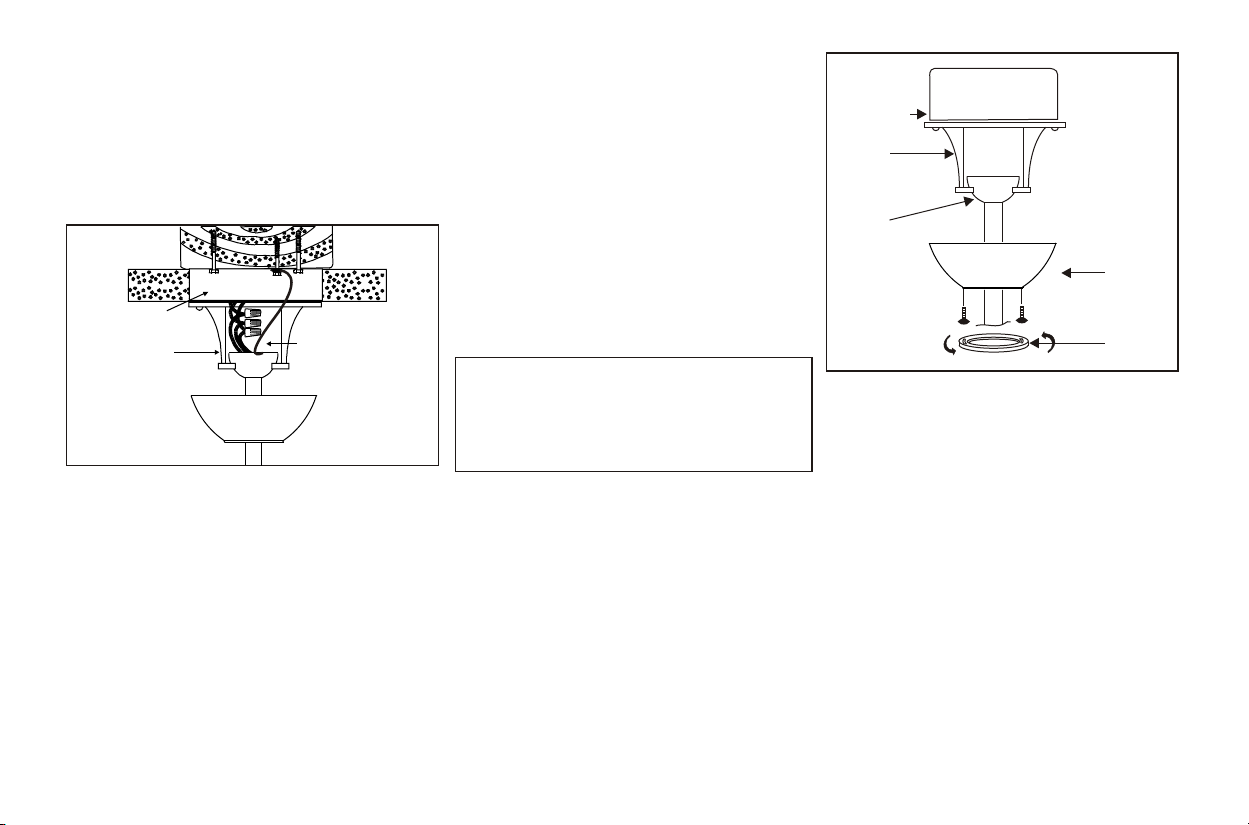
Step 4. (Fig. 10 & 11) If your outlet box
has a ground wire (green or bare copper)
connect the fan ground wire from hanger
ball and hanger bracket to it; otherwise
connect the fan ground wire from the
hanger ball andhanger bracket together.
Step 5. After the splices are made, secure
connectors with electrical tape. Spread the
wires apart so that the green and white
wires are on one side of the outlet box and
the black and blue wires are on the other.
Make sure there are no loose strands or
connections. Turnwire connectors upward
and push thewiring into the outlet box.
Note: Fan must be installed at a maximum
distance of 20 feet from the transmitting unit
for proper signal transmission between the
transmitting unit andthe fan's receivingunit.
Figure 8
Figure 9
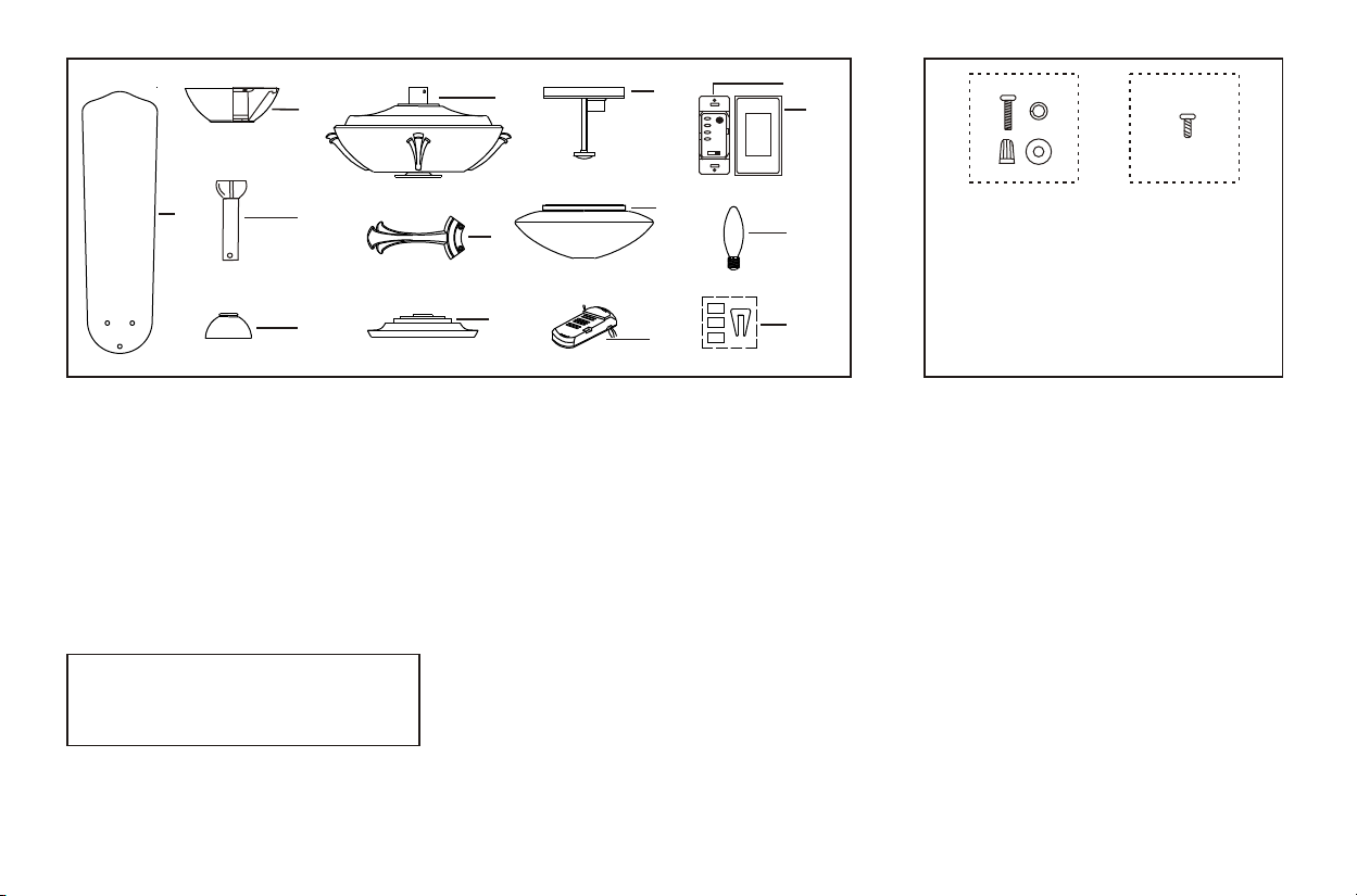
Receiver
Hanger bracket
ONON
5.