HAMPTON BAY HB-5610-WH User manual

THANK YOU
We appreciate the trust and condence you have placed in Hampton Bay through the purchase of this motion
security light. We strive to continually create quality products designed to enhance your home. Visit us online to see
our full line of products available for your home improvement needs. Thank you for choosing Hampton Bay!
USE AND CARE GUIDE
MOTION SECURITY LIGHT
Questions, problems, missing parts?
Before returning to the store, call Hampton Bay Customer Service
8 a.m.-7 p.m., EST, Monday-Friday, 9 a.m. - 6 p.m., EST, Saturday
1-855-HD-HAMPTON
HAMPTONBAY.COM
Item #314423
Model #HB-5610-WH

2
Table of Contents
Table of Contents......................................2
Safety Information....................................2
Warranty ...................................................2
2-Year Limited Warranty ........................2
Specifications...........................................3
Pre-Installation.........................................3
Planning Installation ..............................3
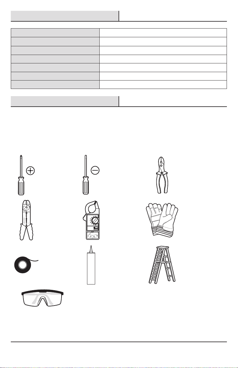
Tools Required .......................................3
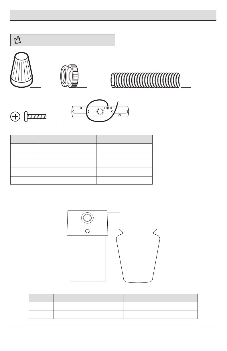
Hardware Included.................................4
Package Contents..................................4
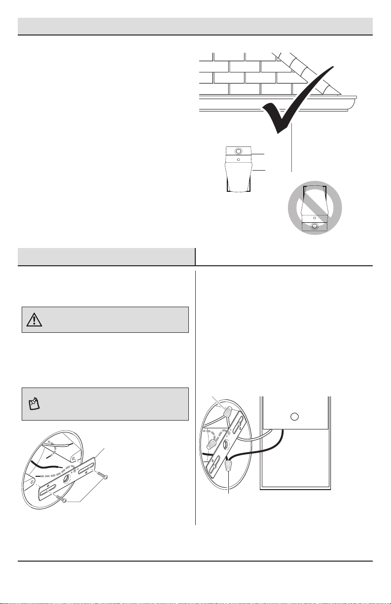
Mounting Locations ...............................5
Installation................................................5
Operation...................................................7
Care and Cleaning ....................................9
Troubleshooting........................................9
Safety Information
PRECAUTIONS
□Please read and understand this entire manual
before attempting to assemble, install, or operate
this light xture.
□This light xture requires a 120V AC power source.
□Some codes require installation by a qualied
electrician.
□This light xture must be properly grounded.
□This light xture should be installed outdoors to a
wall.
□The light xture should be mounted approximately
7 ft. (2.1 m) above the ground. If the light xture is
mounted higher than recommended, the coverage
area will be reduced.
□Do not leave the “ON-TIME” switch in the “TEST”
position. The frequent ON/OFF cycling of the light
xture will reduce the life of the bulb.
WARNING: Turn the power off at the circuit breaker or
fuse. Place tape over the circuit breaker switch and verify
power is off at the light xture.
WARNING: Do not use a SBCFL bulb marked “Not for
use in totally enclosed xtures”.
CAUTION: Burn hazard. Allow the light xture and the
bulb to cool before touching.
NOTICE: When using a CFL bulb, it is recommended to use the
maximum ON-TIME setting. Frequent ON/OFF cycling of the bulb will
reduce its life.
NOTICE: Do not connect this light xture to a dimmer switch or
timer.
□This device complies with Part 15 of the FCC Rules.
Operation is subject to the following two conditions:
(1) this device may not cause harmful interference,
and (2) this device must accept any interference
received, including interference that may cause
undesired operation.
Warranty
2-YEAR LIMITED WARRANTY
WHAT IS COVERED
This product is guaranteed to be free of factory defective parts and workmanship for a period of 2 years from date
of purchase. Purchase receipt is required for all warranty claims.
WHAT IS NOT COVERED
This warranty does not include expendable items (such as light bulbs, batteries, etc.), repair service, adjustment
and calibration due to misuse, abuse or negligence. Unauthorized service or modication of the product or of any
furnished component will void this warranty in its entirety. This warranty does not include reimbursement for
inconvenience, installation, setup time, loss of use, unauthorized service, or return shipping charges. This warranty
is not extended to other equipment and components that a customer uses in conjunction with this product.
Contact the Customer Service Team at 1-855-HD-HAMPTON or visit www.hamptonbay.com.

3 HAMPTONBAY.com
Please contact 1-855-HD-HAMPTON for further assistance.
Specications
Range Up to 30 ft. (9.1 m) - Varies with surrounding temperature
Sensing angle Up to 110°
Electrical load - incandescent Up to 60 watt maximum
Electrical load - self-ballasted CFL (SBCFL) Up to 15 watt maximum dimmable SBCFL
Power requirements 120 VAC, 60 Hz
Operating modes Test, Auto, Manual
Time delay 1, 5, 10 minutes
Pre-Installation
PLANNING INSTALLATION
Before installing the light xture, ensure that all parts are present (see Hardware Included on page 4). If any part is
missing or damaged, do not attempt to assemble, install, or operate this light xture.
Estimated installation time: 30 minutes
TOOLS REQUIRED
Phillips
screwdriver
Flathead
screwdriver Pliers
Wire strippers/
cutters Circuit tester Work gloves
Electrical tape Silicone sealant Ladder
Safety goggles

4
Pre-Installation (continued)
HARDWARE INCLUDED
NOTE: Hardware shown to actual size.
AA BB CC
DD EE
Part Description Quantity
AA Wire connector 3
BB Mounting nut 1
CC Threaded stem 1
DD Mounting bracket screw 2
EE Mounting bracket (not to scale) 1
PACKAGE CONTENTS
Part Description Quantity
A Light xture 1
B Glass globe 1
A
B

5 HAMPTONBAY.com
Please contact 1-855-HD-HAMPTON for further assistance.
Pre-Installation (continued)
MOUNTING LOCATIONS
□Determine the wall mounting location.
□The light xture should be mounted
approximately 7 ft. (2.1 m) above the ground.
If the light xture is mounted higher than
recommended, the coverage area will be
reduced. Wall Mount
Only
Installation
1 Installing the Mounting
Bracket
WARNING: Turn the power off at the circuit breaker or
fuse. Place tape over the circuit breaker switch and verify
power is off at the light xture.
□Remove the existing light xture.
□Install the mounting bracket (EE) to the
junction box using the mounting bracket
screws (DD).
NOTE: Firmly pull on the mounting bracket (EE) to verify
it is securely mounted to the junction box. If necessary,
use the screws that were removed from the existing light
xture.
2 Wiring the Light Fixture
□Connect the light xture wires to the junction
box wires with wire connectors (AA):
□White to white
□Black to black
□Green ground mounting bracket wire to
the house ground wire or grounded metal
junction box.
A
B
DD
EE
AA
AA

6
Installation (continued)
3 Mounting the Light Fixture
□Install the threaded stem (CC) into the
mounting bracket (EE). Leave about 1 in.
(25.4mm) of threads sticking out.
□Place the light xture (A) on the threaded stem
(CC).
□Thread the mounting nut (BB) on the threaded
stem (CC) and tighten securely. Do not
overtighten.
NOTE: Make sure all the wires are inside the junction box
before attaching the light xture (A) to the junction box.
4 Caulking Around the Light
Fixture
□Caulk around the light xture (A) and mounting
surface with silicone sealant (not included).
5 Installing the Bulb and Glass
Globe
□Install a 60 watt maximum light bulb (not
included) into the light xture (A).
□Loosen the decorative screw (1) on the light
xture (A) top and install the glass globe (B).
□Tighten the decorative screw (1) securely. Do
not overtighten.
BB
CC
EE
A
A
A
1
B

7 HAMPTONBAY.com
Please contact 1-855-HD-HAMPTON for further assistance.
Operation
1 Setting the Sensor for Testing
When the “ON-TIME” switch is set to the “TEST”
position, the light xture will operate during the day
or night. The light will stay on for 5 seconds after all
motion is stopped.
□Turn the power on at the circuit breaker or fuse
and turn on the wall switch.
□Set the “ON-TIME” switch to the “TEST”
position.
□Set the “SENS” switch to the “MIN” position.
NOTE: The motion sensor will need to completely warm
up (90 seconds) before beginning the setup process.
ON-TIME
TEST 1 5 10
SENS
MIN MAX
2 Adjusting the Motion Sensor
Detection Zone
□Perform a “walk test”. Walk in an arc across
the front of the motion sensor (2).
□Watch the light. The light will come on when
motion has been detected.
□Stop, wait for the light to turn off, and then
begin walking again.
□Continue this process until the detection zone
has been established.
□Adjust the motion sensor (2) up and down or
rotate the light xture (A) top side to side to
change the motion sensor (2) detection zone.
3 Adjusting the SENS Switch
□To increase the detection zone, slide the
“SENS” switch toward the “MAX” position.
□To decrease the detection zone, slide the
“SENS” switch toward the “MIN” position.
NOTE: The motion sensor is more sensitive to motion
moving across the front of the sensor. The motion sensor
is less sensitive to motion moving directly toward the front
of the sensor.
NOTE: The higher the “SENS” setting (sensitivity), the
greater the possibility of false triggering. To reduce false
triggering, slide the “SENS” switch toward the “MIN”
setting.
ON-TIME
TEST 1 5 10
SENS
MIN MAX
2
A
B

8
Operation (continued)
4 Adjusting the ON-TIME Switch
The “ON-TIME” switch determines the amount of time
the light will stay on full bright after all motion has
stopped.
□Set the “ON-TIME” switch to the 1, 5, or 10
minute position.
ON-TIME
TEST 1 5 10
SENS
MIN MAX
5 Using Manual Mode
Manual mode overrides the motion sensor and
“ON-TIME” control so the light will operate full bright.
This feature only works at night and only for one
night at a time. The motion sensor will reset to motion
sensing mode after 6 hours or sunrise, whichever
comes rst. Manual mode can be toggled on and off
using a wall switch.
□To turn manual mode on, switch the light off
at the wall switch for 2 to 4 seconds and then
back on.
□To turn manual mode off, switch the light off
at the wall switch for 2 to 4 seconds and then
back on.
NOTE: If the power to the light xture is off for more than
5 seconds, allow the motion sensor to warm up prior to
switching to manual mode.
Turn the switch
OFF for 2 to 4
seconds
Turn the
switch
back ON

9 HAMPTONBAY.com
Please contact 1-855-HD-HAMPTON for further assistance.
Care and Cleaning
□To prolong the original appearance, clean with clear water and a soft, damp cloth only.
□Do not use paints, solvents, or other chemicals on this light xture. They could cause a premature
deterioration of the nish. This is not a defect in the nish and will not be covered by the warranty.
□Do not spray with a hose or power washer.
Troubleshooting
Problem Possible Cause Solution
The light will not come on. □The light switch is turned off. □Turn the light switch on.
□The bulb is loose or burned out. □Check the bulb and replace
if burned out.
□The fuse is blown or the circuit breaker
is turned off.
□Replace the fuse or turn the
circuit breaker on.
□Daylight turn-off (photocell) is in effect. □Recheck after dark.
□The circuit wiring is incorrect, if this is
a new installation.
□Verify the wiring is correct.
□The motion sensor is aimed in the
wrong direction.
□Re-aim the motion sensor
to cover the desired area.
□The outside air temperature is close to
the same as a person’s body heat.
□Increase the “SENS” set-
ting.
The light comes on during the
day.
□The motion sensor may be installed in a
relatively dark location.
□The light xture is operat-
ing normally under these
circumstances.
□The “ON-TIME” switch is in the “TEST”
position.
□Set the “ON-TIME” switch
to the 1, 5, or 10 minute
setting.
The light comes on for no
apparent reason.
□The motion sensor may be sensing
small animals or automobile trafc.
□Re-aim the motion sensor.
□The “SENS” switch is set too high. □Decrease the “SENS”
setting.
□The outside temperature is much
warmer or cooler than a person’s body
heat (summer or winter).
□Decrease the “SENS”
setting.
□The light xture is wired through a
dimmer or timer.
□Do not use a dimmer or
timer to control the light
xture. Replace the dimmer
or timer with a standard on/
off wall switch.

10
Problem Possible Cause Solution
The lights stay on continuously. □The motion sensor may be picking up
a heat source like an air vent, dryer
vent, or brightly painted, heat-reective
surface.
□Decrease the “SENS”
setting or reposition the
motion sensor.
□The motion sensor is in manual mode. □Switch the motion sensor
to auto. See Using Manual
Mode on page 8.
□The light xture is wired through a
dimmer or timer.
□Do not use a dimmer or
timer to control the light
xture. Replace the dimmer
or timer with a standard on/
off wall switch.
□The light xture is on the same circuit
as a motor, transformer, or uorescent
bulb.
□Install the light xture on
a circuit without motors,
transformers, or uorescent
bulbs.
The lights ash on and off. □Heat is being reected from other
objects and may be turning the motion
sensor on and off.
□Reposition the motion
sensor.
□The motion sensor is in “TEST” mode
and warming up.
□Flashing is normal under
these conditions.
□The CFL bulb may not be a dimmable
type bulb.
□Use only dimmable self-
ballasted CFL (SBCFL)
bulbs.
Troubleshooting (continued)

11 HAMPTONBAY.com
Please contact 1-855-HD-HAMPTON for further assistance.

Questions, problems, missing parts?
Before returning to the store, call Hampton Bay Customer Service
8 a.m.-7 p.m., EST, Monday-Friday, 9 a.m. - 6 p.m., EST, Saturday
1-855-HD-HAMPTON
HAMPTONBAY.COM
Retain this manual for future use.
208316-04A

GRACIAS
Agradecemos la fe y la conanza que usted ha depositado en Hampton Bay al comprar esta luz de seguridad por
movimiento. Procuramos crear continuamente productos de calidad diseñados para mejorar su hogar. Visítenos en
internet para ver nuestra línea completa de productos disponibles que necesita para el mejoramiento de su hogar.
¡Gracias por escoger Hampton Bay!
GUÍA PARA EL USO Y CUIDADO
LUZ DE SEGURIDAD POR MOVIMIENTO
¿Tiene preguntas, problemas o piezas faltantes?
Antes de devolverlo a la tienda, llame a Servicio al Cliente de Hampton Bay
de 08 a.m.-7 p.m., EST, Lunes - Viernes, 09 a.m.-6 p.m., EST, sábado.
1-855-HD-HAMPTON
HAMPTONBAY.COM
Articulo #314423
Modelo #HB-5610-WH

14
Contenido
Contenido................................................14
Información de seguridad......................14
Garantía...................................................14
2 años de garantía limitada .................14
Especificaciones.....................................15
Antes de la instalación...........................15
Planicación de la Instalación .............15
Herramientas Requeridas ....................15
Ferretería Incluida................................16
Contenido del Paquete.........................16
Sitios Para el Montaje..........................17
Instalación ..............................................17
Operación................................................19
Cuidado y limpieza .................................21
Análisis de averías .................................21
Información de seguridad
PRECAUCIONES
□Por favor lea y entienda todo este manual antes de
tratar de ensamblar, instalar u operar este aparato
de luz.
□Esta lámpara requiere una fuente de alimentación
de 20 voltios de CA.
□Algunos códigos exigen que la instalación la realice
un electricista calicado.
□Este aparato de luz debe estar correctamente
conectado a tierra.
□A esta lámpara se la debe instalar al aire libre
sobre una pared.
□Esta lámpara debe ser instalada aproximadamente
a 7 pies (2,1 m) por encima del suelo. Si se monta
la lámpara a una altura superior a la recomendada,
se reducirá el área de cobertura.
□No deje el interruptor de “DURACIÓN” (“ON-TIME)
en la posición “PRUEBA” (“TEST”). La alternancia
frecuente entre ENCENDIDO/APAGADO (ON/OFF)
reducirá la vida de la bombilla.
ADVERTENCIA: Desconecte la energía eléctrica en el
disyuntor o en el fusible. Coloque cinta aislante sobre el
interruptor disyuntor y compruebe que no haya energía
eléctrica en el aparato de luz.
ADVERTENCIA: No utilice un foco uorescente
compacto con balasto incorporado con la inscripción “No
usar en luminarias completamente cerradas”.
PRECAUCIÓN: Peligro de quemaduras. Deje que el
aparato de luz y la bombilla se enfríen antes de tocarlos.
AVISO: Cuando esté usando un foco CFL, se recomienda congurar
al máximo el interruptor de ON-TIME (DURACIÓN DE TIEMPO). El
encender/apagar frecuentemente el foco disminuirá el ciclo de vida
del mismo.
AVISO: No conecte este aparato de luz a un interruptor reductor de
luz ni a un temporizador.
□Este aparato cumple con la Parte 15 de las
Reglas de la FCC. La operación está sujeta a las
dos siguientes condiciones: (1) este aparato no
puede causar interferencias perjudiciales y (2)
este aparato debe aceptar cualquier interferencia
recibida, incluyendo una interferencia que pueda
causar un funcionamiento indeseado.
Garantía
2 AÑOS DE GARANTÍA LIMITADA
LO QUE SE CUBRE
Se garantiza que este producto no tiene partes defectuosas de fábrica o de mano de obra por un período de 2 años
desde la fecha de compra. Se necesita el recibo de compra para todos los reclamos de garantía.
LO QUE NO SE CUBRE
Esta garantía no incluye los artículos reemplazables (como bombillas, baterías, etc.), el servicio de reparación, ajuste
y calibración debido al mal uso, abuso o negligencia. Los servicios no autorizados o las modicaciones hechas al
producto o a cualquier componente invalidarán esta garantía en su totalidad. Esta garantía no incluye reembolso por
inconveniencia, instalación, tiempo de instalación, perdida de uso, servicio no autorizado, o gastos de envío. Esta
garantía no se extiende a otros equipos o componentes que el consumidor usa junto con este producto.
Póngase en contacto con el personal de servicio al cliente al 1-855-HD-HAMPTON o visite el sitio www.hamptonbay.com.

15 HAMPTONBAY.com
Por favor, póngase en contacto al 1-855-HD-HAMPTON para obtener más ayuda.
Especicaciones
Alcance Hasta 30 pies (9,1 m) – Varía con la temperatura circundante
Ángulo de detección Hasta 110°
Carga eléctrica-Incandescente Hasta 60 vatios máximo
Carga eléctrica- estabilización incorporada
CFL (SBCFL)
Hasta 15 vatios máximo luz reducible SBCFL
Requisitos de la energía eléctrica 120 VCA, 60 Hz
Fases de operación Prueba, automática, manual
Retardo de tiempo 1, 5, 10 minutos
Antes de la instalación
PLANIFICACIÓN DE LA INSTALACIÓN
Antes de instalar el aparato de luz, esté seguro que estén todas las piezas (vea Ferretería incluida en la página 16).
Si cualquier pieza falta o está dañada, no intente ensamblar, instalar ni operar este aparato de luz.
Tiempo estimado para la instalación: 30 minutos
HERRAMIENTAS REQUERIDAS
Destornillador
phillips
Destornillador
plano Alicates
Peladores/
cortadores de
cables
Probador de
circuitos
Guantes de
trabajo
Cinta aislante Sellador de
silicona Escalera
Gafas de
seguridad

16
Antes de la instalación (continuación)
FERRETERÍA INCLUIDA
NOTA: La ferretería se muestra en su tamaño real
AA BB CC
DD EE
Pieza Descripción Cantidad
AA Capuchón para cable 3
BB Tuerca de montaje 1
CC Espiga roscada 1
DD Tornillo del soporte de montaje 2
EE Soporte de montaje (no está a escala) 1
CONTENIDO DEL PAQUETE
Pieza Descripción Cantidad
A Lámpara 1
B Globo de cristal 1
A
B

17 HAMPTONBAY.com
Por favor, póngase en contacto al 1-855-HD-HAMPTON para obtener más ayuda.
Antes de la instalación (continuación)
SITIOS PARA EL MONTAJE
□Determine el sitio para el montaje en pared.
□Esta lámpara debe ser instalada
aproximadamente a 7 pies (2,1 m) por encima
del suelo. Si se monta la lámpara a una altura
superior a la recomendada, se reducirá el área
de cobertura. Solo para montaje
sobre pared
Instalación
1 Instalación del soporte de
montaje
ADVERTENCIA: Desconecte la energía eléctrica en el
disyuntor o en el fusible. Coloque cinta aislante sobre el
interruptor disyuntor y compruebe que no haya energía
eléctrica en el aparato de luz.
□Retire el aparato de luz existente.
□Instale el soporte de montaje (EE) a la caja de
conexiones con los tornillos del soporte de
montaje (DD).
NOTA: Hale con rmeza el soporte de montaje (EE) para
vericar que esté bien montado en la caja de conexiones.
Si es necesario, use los tornillos que fueron retirados del
aparato de luz anterior.
2 Cableado del aparato de luz
□Conecte los cables del aparato de luz a los
cables de la caja de conexiones con los
capuchones para cables (AA):
□Blanco con blanco
□Negro con negro
□El alambre verde de conexion a tierra
del soporte de montaje al alambre de
conexion a tierra de la casa o a la caja de
conexiones metálica conectada a tierra.
A
B
DD
EE
AA
AA

18
Instalación (continuación)
3 Montaje del aparato de luz
□Instale la espiga roscada (CC) en el soporte de
montaje (EE). Deje que salga cerca de 1 pulg.
(25,4 mm) de alambre .
□Coloque la lámpara (A) sobre la espiga roscada
(CC).
□Enrosque la tuerca de montaje (BB) en la
espiga roscada (CC) y apriete rmemente. No
apriete excesivamente.
NOTA: Asegúrese de que todos los alambres estén dentro
de la caja de conexiones antes de conectar la lámpara (A)
a la caja de conexiones.
4 Calafatee alrededor del aparato
de luz
□Calafatee alrededor de la lámpara (A) y de la
supercie de montaje con sellador de silicona
(no incluido).
5 Instalación de la bombilla y del
globo de cristal
□Instale una bombilla de 60 vatios máximo (no
incluida) en la lámpara (A).
□Aoje el tornillo decorativo (1) en la parte
superior de la lámpara (A) e instale el globo
de cristal (B).
□Apriete rmemente el tornillo decorativo (1).
No apriete excesivamente.
A
1
B
BB
CC
EE
A
A

19 HAMPTONBAY.com
Por favor, póngase en contacto al 1-855-HD-HAMPTON para obtener más ayuda.
Operación
1 Calibración del detector para
prueba
Cuando el interruptor de “DURACIÓN” (“ON-TIME”) se
ja en la posición “PRUEBA” (“TEST”) el aparato de luz
operará durante el día o la noche. La luz permanecerá
encendida 5 segundos después que todo movimiento
se ha detenido.
□Conecte la energía eléctrica en el disyuntor o en
el fusible y encienda el interruptor de la pared.
□Fije el interruptor de “DURACIÓN” en la
posición “PRUEBA (“TEST”).
□Fije el interruptor “SENS” a la posición “MIN”.
NOTA: El detector de movimiento necesitará calentarse
completamente (90 segundos) antes de empezar el
proceso de puesta a punto.
ON-TIME
TEST 1 5 10
SENS
MIN MAX
2 Regulación de la zona de
detección del detector de
movimiento
□Haga una “prueba caminando”. Camine
transversalmente a la parte frontal del detector de
movimiento (2) siguiendo la trayectoria de un arco.
□Observe la luz. La luz se encenderá cuando el
movimiento es detectado.
□Deténgase, espere que la luz se apague, y
luego empiece a caminar de nuevo.
□Continúe este proceso hasta que la zona de
detección haya sido establecida.
□Ajuste el detector de movimiento (2) hacia
arriba y hacia abajo o gire la parte superior de la
lámpara (A) de lado a lado para cambiar la zona
de detección del detector de movimiento (2) .
3 Ajuste del interruptor SENS
□Para aumentar la zona de detección, deslice el
interruptor “SENS” hacia la posición “MAX”.
□Para disminuir la zona de detección, deslice el
interruptor “SENS” hacia la posición “MIN”.
NOTA: El detector de movimiento es más sensible al
movimiento transversal a la parte frontal del detector. El
detector de movimiento es menos sensible al movimiento que
se dirige directamente hacia la parte frontal del detector.
NOTA: Mientras mayor sea la calibración del “SENS”
(sensibilidad), mayor será la posibilidad de falsas alarmas.
Para reducir las falsas alarmas deslice el interruptor
“SENS” hacia el ajuste “MIN”.
ON-TIME
TEST 1 5 10
SENS
MIN MAX
2
A
B

20
Operación (continuación)
4 Regulación del interruptor de
DURACIÓN
El interruptor de DURACIÓN determina el lapso de
tiempo que la luz permanece encendida con todo su
brillo luego que ha cesado el movimiento.
□Coloque el interruptor de DURACIÓN en la
posición 1, 5 o 10 minutos.
ON-TIME
TEST 1 5 10
SENS
MIN MAX
5 Uso del la fase manual
La fase manual anula el detector de movimiento (C) y
el control de duración (“ON-TIME”), de esta forma la
lámpara operará con todo su brillo. Esta característica
funciona solamente en la noche y solamente una noche
a la vez. El detector de movimiento (C) se reiniciará en
la modalidad de detección de movimiento después de
6 horas o cuando salga el sol, lo que ocurra primero. La
fase manual puede también alternar entre encendido y
apagado mediante el interruptor de pared.
□Para encender la fase manual, apague la
luz con el interruptor de pared entre 2 a 4
segundos y luego vuelva a encenderla.
□Para apagar la fase manual, apague la luz con
el interruptor de pared entre 2 a 4 segundos y
luego vuelva a encenderla.
NOTA: Si la energía eléctrica al aparato de luz es
apagada por más de 5 segundos, deje que el detector de
movimiento se caliente antes del cambio a la fase manual.
Apague el
interruptor
entre 2 a 4
segundos
Vuelva a
encender el
interruptor
This manual suits for next models
1
Table of contents
Languages:
Other HAMPTON BAY Floodlight manuals
Popular Floodlight manuals by other brands

ArtFox Lightning
ArtFox Lightning FLEX BEAM K8 RGBW user manual

PROLED
PROLED HIGH BAY FLOODLIGHT 70 installation manual

Infinity
Infinity iW-1915 Pixel manual

Eaton
Eaton Crouse-hinds series Installation & maintenance information

Ledino
Ledino Bilk 10 instruction manual

LUX LUMEN
LUX LUMEN BigEye IP67 user manual

Cooper Lighting
Cooper Lighting ALL-PRO FT1850LW instruction manual

XanLite
XanLite PRAR30WMDCW user manual

BEGA
BEGA 84 377 Instructions for use

nedis
nedis WIFILOFC20FBK quick start guide

Francis Searchlights
Francis Searchlights A7180 VH500 User instruction

Larson Electronics
Larson Electronics WAL-QP-2X-25 instruction manual