HAMPTON BAY LPAB10 User manual

THANK YOU
We appreciate the trust and condence you have placed in Hampton Bay through the purchase of this adjustable bracket. We strive to
continually create quality products designed to enhance your home. Visit us online to see our full line of products available for your home
improvement needs. Thank you for choosing Hampton Bay!
USE AND CARE GUIDE
LOW PROFILE ADJUSTABLE BRACKET
Questions, problems, missing parts? Before returning to the store,
call Hampton Bay Customer Service
8 a.m. - 7 p.m., EST, Monday – Friday, 9 a.m. – 6 p.m., EST, Saturday
1-855-HD-HAMPTON
HAMPTONBAY.COM
Item #235856, 235860, 23586
Model # LPAB10, LPAB12, LPAB14

2
Table of Contents
Table of Contents ...................................2
Warranty ..........................................2
Pre-Installation.....................................3
Planning Installation ...............................3
Bracket Size Selection .............................4
Number of Brackets Needed .........................4
Bracket Spacing ..................................4
Installation ........................................5
Mounting Option 1 .................................5
Mounting Option 2 .................................5
Mounting Option 3 .................................6
Adjusting Set Screws & Installing Countertop ...........6
Warranty
LIMITED WARRANTY
WHAT IS COVERED
This product is guaranteed to be free from defects in material and workmanship under normal and proper usage for a period of ve (5)
years from the date of purchase.
WHAT IS NOT COVERED
The Victory Bracket has an intended purpose. If used outside of that purpose, the product will not be warranted and Hampton Bay shall not
be held responsible for any damage that may occur due to accident, abuse, misuse or negligence. The following products are not covered
under this warranty: (1) brackets that have been altered, modied, neglected or poorly maintained; (2) brackets that are purchased in used
condition, not in original packaging, or from an unauthorized dealer or distributor; (3) brackets that have been damaged during transit or
shipping.
The following damages are not covered under this warranty: (1) damage to persons or property due to improperly installed or repaired
brackets; (2) damage from causes other than defects in materials and workmanship such as a purchaser’s or installer’s lack of skill,
competence or experience.
Contact the Customer Service Team at 1-855-HD-HAMPTON or visit www.HAMPTONBAY.com.

3 HAMPTONBAY.COM
Please contact 1-855-HD-HAMPTON for further assistance.
Pre-Installation
PLANNING INSTALLATION
NOTE: Wall thickness must be between 3/4 in. and 4 in..
NOTE: Place bracket directly under seams in countertop.
TOOLS REQUIRED
Phillips
screw driver Drill ¼ in. drill bit Level
Router Wood chisel Caulk
HARDWARE INCLUDED
NOTE: Hardware shown to actual size.
AA BB CC
Part Description Quantity
AA Phillips head wood screws 2
BB Set screws 2
CC Hex wrench (not to scale) 1

4
Pre-Installation (continued)
PACKAGE CONTENTS
Part Description Quantity
A Low Prole Adjustable Bracket 1

5 HAMPTONBAY.COM
Please contact 1-855-HD-HAMPTON for further assistance.
Pre-Installation (continued)
1 Select the correct bracket size
□The appropriate bracket size is determined by the wall
thickness and overhang length.
□Use the table below to nd the correct bracket size for
your countertop.
2 Determine the number of brackets
needed
□Generally, you will need one bracket every 12-18 in..
□The table below gives bracket requirements for
countertops of various widths.
3 Calculate the bracket spacing
□The rst and last brackets should be placed 3 in. from the
end/corner of the countertop.
□The spacing between brackets can be determined using
the formula below:
4 Choose your desired mounting option
Spacing (S) = (W) Width - 6
# of brackets - 1
Overhang Length (in.)
Wall Thickness (in.)
8 9 10 11 12 13 14 15 16 17 18
¾8 8 8 10 10 10 12 12 12 14 14
28 8 10 10 10 12 12 12 14 14 16
310 10 10 12 12 12 14 14 14 16 16
410 10 12 12 12 14 14 14 16 16 16
Width Brackets
24 – 28 in. 2
29 – 48 in. 3
49 – 68 in. 4
69 – 88 in. 5
89 – 108 in. 6
SSSS
S W
W
Option 1: Mount to Cabinet
Wall thickness usually ¾ in. to 2 in.
Option 3: Two Level, Wall Mount
Wall thickness usually 4 in.
Option 2: Single Level, Wall Mount
Wall thickness usually 4 in.

6
Installation
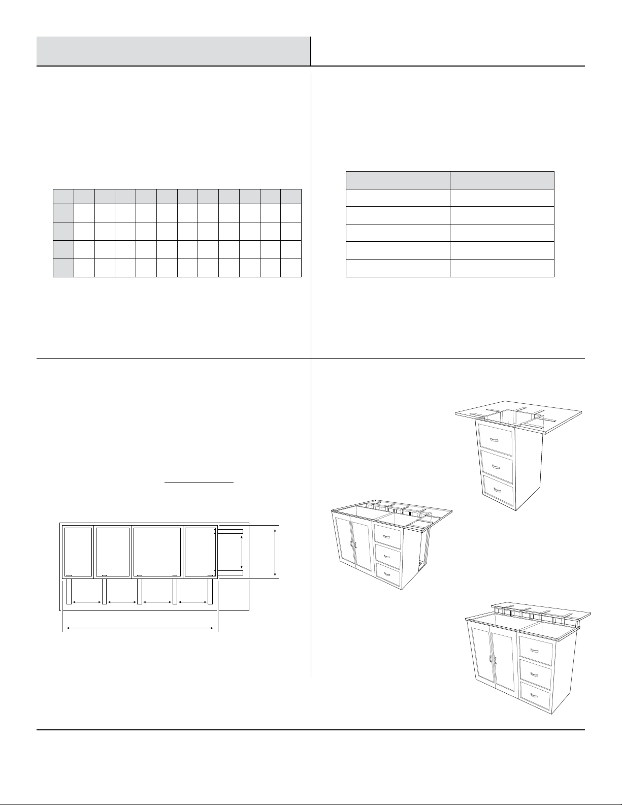
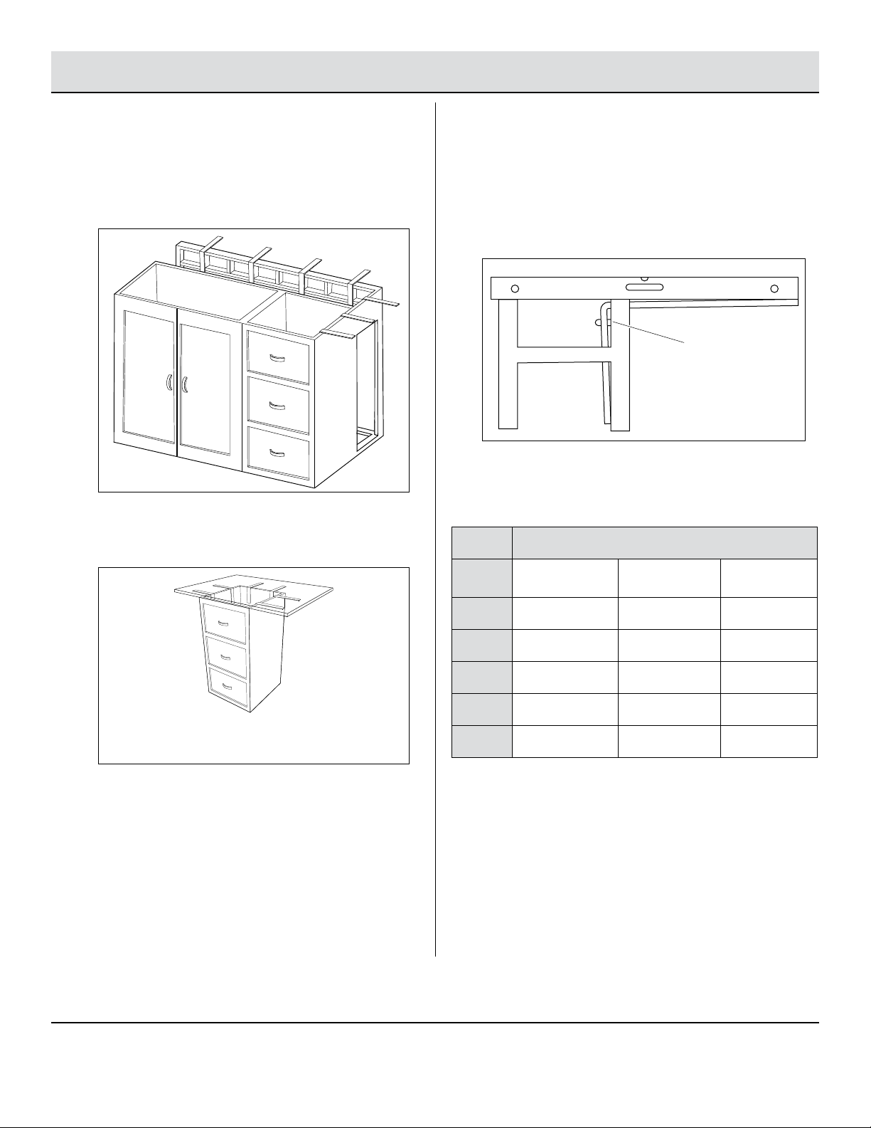
1 Option 1: Mounting Bracket to
Back or Side of Cabinet
NOTE: If cabinet wall is less than ¾ in. thick, attach
¾ in. plywood to inside of cabinet using four wood
screws (not included).
□Notch the top of the wall ¼ in. by 2-1/8 in.. Cut a ¼ in.
radius on the inside wall.
□If mounting to the side of the cabinet, use a jigsaw to cut a
slot at least ½ in. by 2-1/8 in. in any support that obstructs
the bracket’s t.
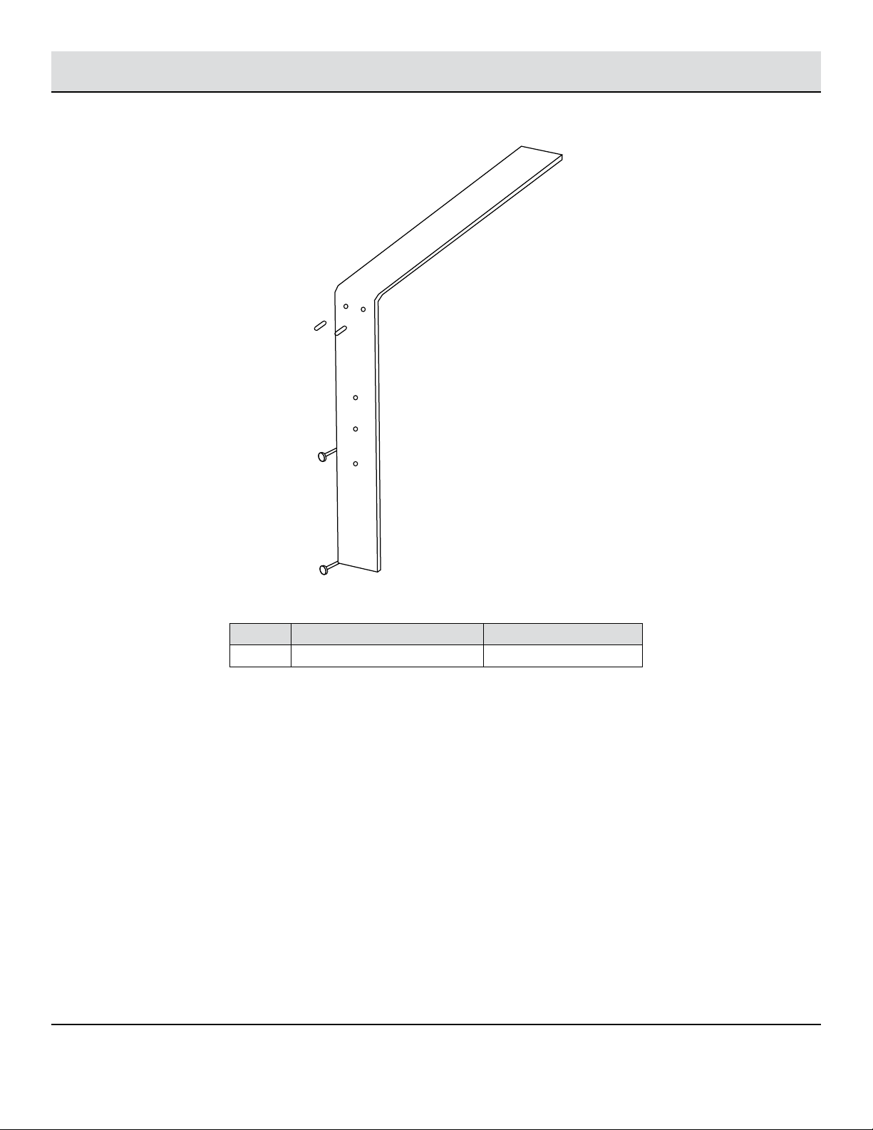
□Using the bracket as a template, mark and drill 1/8 in. pilot
holes ½ in. deep.
□Make sure the bracket ts tightly on the wall surface and
there is a 1/16 in. gap (very important) from the top of the
bracket to the top of the wall. If not, remove material in
the notch or the radius.
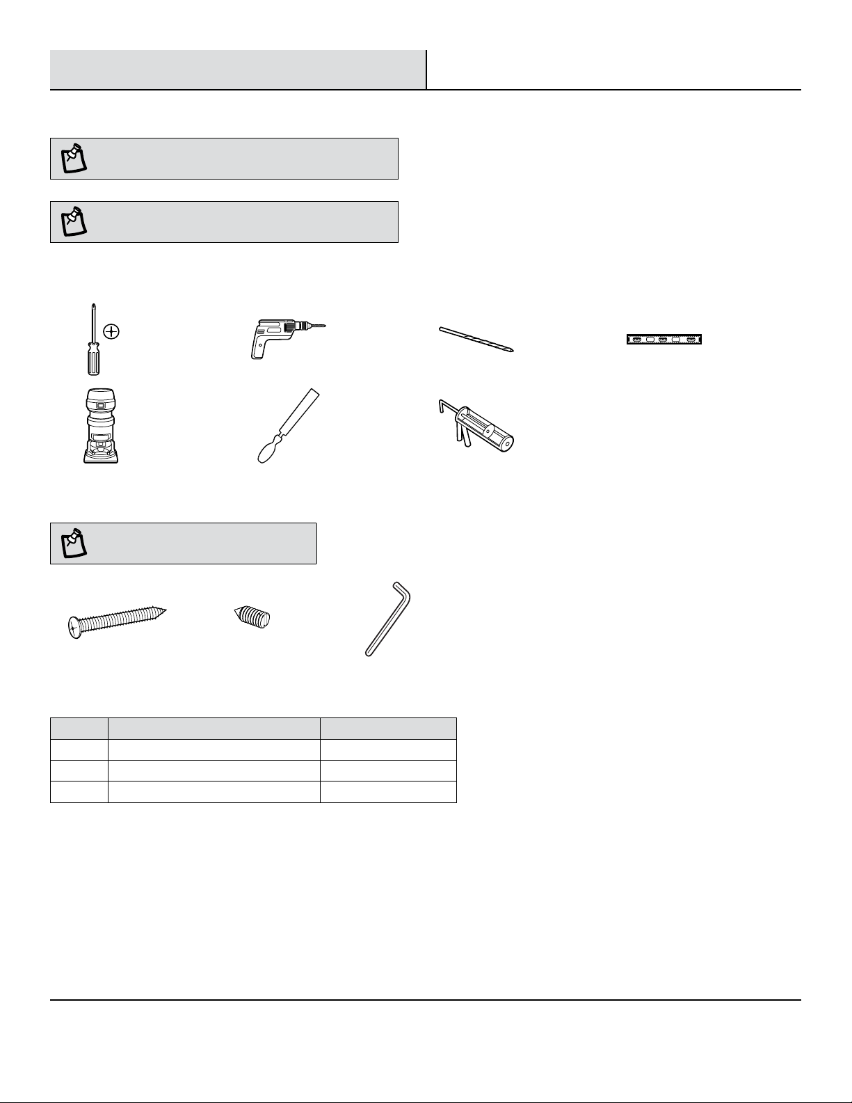
□Attach the bracket to the wall using the two (2) ¾ in. wood
screws (AA), one in each the bottom and middle holes.
□See Adjusting Set Screws and Installing Countertop on
page 7.
2 Option 2: Mounting Bracket to
Front of Cabinet with Doors
NOTE: If there is not a 2 in. wide surface to mount the
bracket on the front wall, a 1 in. x 3 in. x 12 in. piece of
wood can be mounted to the cabinet sidewall several inches
away from the front face. The distance from the front face
to the back side of the 1 in. x 3 in. x 12 in. becomes the wall
thickness when sizing the bracket.
□Attach each bracket to a 1 in. x 3 in. x 12 in. piece of wood
using the two (2) wood screws (AA) provided.
□Fit-check the bracket on the sidewall and mark the top wall
of the front cabinet where each bracket is located.
□Notch the top wall ¼ in. by 2-1/8 in. at each marked
location.
□Attach the 1 in. x 3 in. x 12 in. pieces of wood to the sides
of the cabinet using three (3) wood screws (not provided),
making sure that there is ¼ in. gap (very important) from
the top of the 1 in. x 3 in. x 12 in. pieces of wood to the top
of wall.
□See Adjusting Set Screws and Installing Countertop on
page 7.
AA
AA

7 HAMPTONBAY.COM
Please contact 1-855-HD-HAMPTON for further assistance.
Installation (continued)
3 Option 3: Mounting Bracket to Wall
□Install 2x4 in. cross braces between the wall studs to
support the brackets. The brackets can be mounted on a
stud or any location on the cross braces.
□For a single-level countertop, notch the top of the 2x4 in.
cap ¼ in. by 2-1/8 in. and cut a ¼ in. radius on the inside
wall.
□For a two-level countertop, make additional notches on the
back of the wall ½ in. deep by 2-1/8 in. so the backsplash
or nished surface can cover the brackets.
□Make sure the brackets t tightly on the wall surface and
there is a 1⁄16 in. gap (very important) from the tops of the
brackets to top of the wall.
□Attach each bracket to the wall using two (2) ¾ in. wood
screws (AA), one in each the bottom and middle holes.
□Continue to Adjusting Set Screws and Installing Countertop.
4 Adjusting Set Screws and Installing
Countertop
□Turn the set screws (BB) to level the end of the bracket
with other parts of the counter.
□Use a level to conrm the end of the bracket is level and
both set screws (BB) are equally engaged.
□Turn both set screws (BB) the additional of number of turns
listed in the table below. This provides support at the end
of the bracket and ensures uniform support of your specic
countertop by preloading the bracket.
□Install the countertop and apply caulk around the perimeter
of the bracket under the countertop.
Counter Weight (lbs/sq ft)
Bracket
Size
18
1¼ in. granite
12
¾ in. granite
6
lighter material
8 in. 2.5 turns 1.7 turns 0.8 turns
10 in. 3 turns 2 turns 1 turns
12 in. 3.5 turns 2.3 turns 1.2 turns
14 in. 4 turns 2.7 turns 1.3 turns
16 in. 4.5 turns 3 turns 1.5 turns
BB

Questions, problems, missing parts? Before returning to the store,
call Hampton Bay Customer Service
8 a.m. - 7 p.m., EST, Monday – Friday, 9 a.m. – 6 p.m., EST, Saturday
1-855-HD-HAMPTON
HAMPTONBAY.COM
Retain this manual for future use.
This manual suits for next models
5
Table of contents
Popular TV Mount manuals by other brands

Metra Electronics
Metra Electronics 95-8910S installation instructions

Philips
Philips SB7S19S Specifications

3M
3M SALA Sealed Block Bracket Assembly & Operation guide

KSL
KSL Simpler 12ET installation instructions

FITUEYES
FITUEYES TT306501GB installation instructions

HQ
HQ TVS-HQ-TFSB01B Assembly instructions