HanaNet 400S User manual

WWW.HANANET.COM
USER’S
MANUAL
Stand Alone Type
HANANet
DVR SYSTEM
Revision Date : 2005. 03. 15.
Firmware 2.4 Version
Ex-Factory Date :
041231 050315041130

WWW.HANANET.COM
• MANUAL CHANGE LIST
①PTZ Control (p.26)
* PRESET Function Add : PELCO-D PROTOCOL
* SWING Function Add : DONGYANG CAMERA (D-MAX)
F/W VER. 1.6
Amend Date : 2004.11.30
♦ Manual is Updated as Below.
F/W VER. 2.0
Amend Date : 2004.12.31
① 2 Way Audio Conference (p. 39)
* 2 Way Audio Supply between Remote Client
② Dynamic IP (DHCP) support (p.42)
* DHCP Network IP Supply
③ CD-RW Backup (by AVI) (p.46)
* CD Backup Supply
1. Server DVR
1. Server DVR
2. Remote PC
①Web Client (p.65)
* Remote Agent Viewer (Live only)
② Multi Client User (p.62)
* Max 4 people
③ Remote Setup (p.48)
④ 2 Way Audio Conference (p.39)
* 2 Way Audio Supply between DVR Server

WWW.HANANET.COM
• MANUAL CHANGE LIST
F/W VER. 2.4
Amend Date : 2005.03.15
♦ Manual is Updated as Below.
1. Server DVR
① Authority Change(p.62)
Operator : Live/PTZ
Manager : Live/PTZ + search
Administrator: All authority
② PTZ Supplied Protocol Addition(p.37)
③ DDNS Support(p.41)
Connection the DVR by Fixing Domain Name
--------------------------------------------------------------
※ We revised some in proper texts additionally better understanding.
p22. Hard Disk Format
p26. PRESET Ability Setting at Protocol D
p48. Client System Demanding Subject Change
p67 Explain Vocabulary

WWW.HANANET.COM
•INDEX
• CHAPTER 1. Specification & System organization
1. Specification -------------------------------------------------------------- 6
2. Product Contents List ------------------------------------------------------- 9
3. System Organization -------------------------------------------------------- 10
•CHAPTER 2. Description
1. Front Panel -------------------------------------------------------------- 12
2. Rear Panel --------------------------------------------------------------- 14
3. Remote Controller ---------------------------------------------------------- 15
• CHAPTER 3. Installation
1. Hard Disk Installation ------------------------------------------------------- 16
2. CD-RW & Hard Disk Installation ----------------------------------------------- 18
3. Camera Connection -------------------------------------------------------- 20
4. Monitor Connection -------------------------------------------------------- 20
5. Computer Connection ------------------------------------------------------ 20
6. Network Connection -------------------------------------------------------- 20
7. Alarm/Relay/PTZ Connection ------------------------------------------------- 21
8. Power Connection --------------------------------------------------------- 21
9. Finishing Installation -------------------------------------------------------- 22
※ Hard Disk Format ------------------------------------------------------- 22
•CHAPTER 4. Display
1. System Power ON --------------------------------------------------------- 23
2. Screen View Selection ------------------------------------------------------ 23
3. Screen Rotation Mode (SCR MODE) -------------------------------------------- 24
4. PTZ/FOCUS Control -------------------------------------------------------- 24
5. System Power OFF -------------------------------------------------------- 27
•CHAPTER 5. Search
⊙ Go to Search Mode --------------------------------------------------------- 28
1. Search by Date/Time ------------------------------------------------------- 28
2. Search by Event --------------------------------------------------------- 29

WWW.HANANET.COM
•INDEX
• CHAPTER 6. MENU
⊙ Go to Menu ---------------------------------------------------------- 31
⊙ Initial Menu ---------------------------------------------------------- 31
1. Display ------------------------------------------------------------------ 32
2. Record ------------------------------------------------------------------ 32
3. Camera ----------------------------------------------------------------- 37
4. Audio ------------------------------------------------------------------- 38
5. Alarm ------------------------------------------------------------------- 39
6. System ------------------------------------------------------------------ 40
7. Backup ----------------------------------------------------------------- 46
• CHAPTER 7. CLIENT
⊙ Remote Program Install ----------------------------------------------------- 48
1. Display --------------------------------------------------------------- 51
2. Search ---------------------------------------------------------------- 54
3. Setting ---------------------------------------------------------------- 61
4. Web-Client ------------------------------------------------------------- 65
※ Explain the Vocabulary ------------------------------------------------------- 67

WWW.HANANET.COM
6
• Specification & Organization
1. Specification (400S)

WWW.HANANET.COM
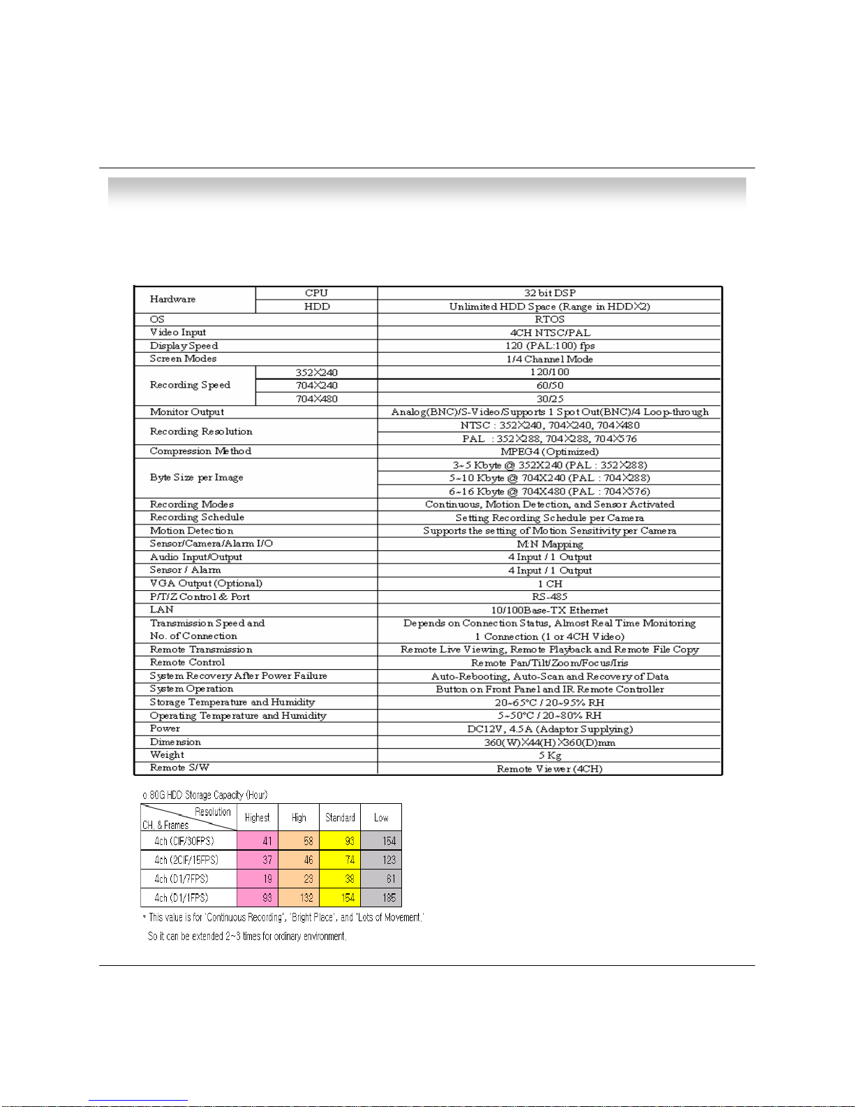
1. Specification (400SN)
1 x line-out, RCA socketAudio output
4 x line-in, RCA socketsAudio inputs
1 x 1Vp-p, CVBS, 75ohms, BNCSpot output
1 x CVBS/S-VHS, VGA (option)Monitor outputs
4 x 1Vp-p, CVBS, 75ohms, BNC, looping inputsVideo inputs
TriplexSimplex/Duplex operation
12x12 grid, Sensitivity levels: 10Activity detection
For monitors with Multi Sync Function onlyVGA
5 secs(Pre), 3 mins(Post), programmable per cameraPre/Post alarm recording
Single and quad picturePlayback
Web Monitoring (IE), Remote Viewer,
Simultaneously 4 users support
Remote Access
Daily, Weekly adjust specific Hr per channelRecord Scheduling
Up to 1,000,000 for user login/out, config changes,
remote access, connects/disconnects
Event/Log search
ProgrammableCovert camera operation
Real time:25 Fps (PAL), 30Fps(NTSC) per cameraMonitor display
2-way Audio conferenceAudio
PAL/NTSCVideo standard
352x240,704x240,704x480(NTSC)
352x288,704x288,704x576(PAL)
Resolution
4 x TTL, programmable as NC/NOAlarm inputs
USB 1.1 memory stick or LG CD-RWSecondary Storage (Option)
Unlimited within 3 x HDDHard disk capacity
3-5 Kbyte (352x240, 352x288)
5-10 Kbyte (704x240, 704x288)
6-16 Kbyte (704x480, 704x576)
Image size
352x240 : 120/100 (NTSC/PAL)
704x240 : 60/50 (NTSC/PAL)
704x480 : 30/25 (NTSC/PAL)
Recording speed
Modified Mpeg4Compression standard
• Specification & Organization
7

WWW.HANANET.COM
8
• Specification & Organization
5kg(400S), 5.5kg(400SN)Weight
44x360x360mm(400S), 66x360x360mm(400SN)Dimensions (HxWxD)
BlackColor
Steel metalHousing
5℃to 50℃Temperature range
Approx. 60wattsPower consumption
100VAC-240VAC, 1/0.5A, 60/50HzSupply voltage
RS-485 interfacePTZ Control
Live View, Live Recording, Search, Set-up, Back-upRemote Function
10/100-Base-TX, RJ-45Ethernet interface
Default - English,
Option - Spanish, Chinese, Japanese, Dutch, Portuguese
Menu languages
Ver 2.4Firmware Version
Up to 5 sec., programmable per cameraPre-alarm recording
8 levelsNetwork Speed Control
AVI, JPG, BMPBack-up file formats
1 x Relay with NO/NC contact;
30VDC/1A, 125VAC/0.5A resistive
Alarm outputs
185Hr154Hr132Hr93Hr4Ch (D1/1Fps) 704x480
61Hr38Hr23Hr19Hr4Ch (D1/7Fps) 704x480
123Hr74Hr46Hr37Hr4Ch (2CIF/15Fps) 704x240
154Hr93Hr58Hr41Hr4Ch (CIF/30Fps) 352x240
LowStandardHighHighestQuality
Record
The reference recording time table

WWW.HANANET.COM
9
• Specification & Organization
2. Product contents List
Please Confirm the Contents When open Package.
①Basic Contents
①Option Contents
AVR-400S
Remote Controller
User’s Manual Remote Client
Program Install CD
AAA Battery X 2
HDD VGA OUT Install Kit
12V Adaptor Power Cable
CD-RW (400SN)

WWW.HANANET.COM
10
• Specification & Organization
3. Organization (400S)
NETWORK
Camera #1-4
Alarm Sensor #1-4 Relay Out
VCR VGA
Monitor AV Monitor
Remote Client PC
Image Printer
Remote
Controller
AVR-400S
Video In
Video Out
TCP/IP
Alarm Input/Out

WWW.HANANET.COM
11
• Specification & Organization
3. Organization (400SN)
NETWORK
Camera #1-4
Alarm Sensor #1-4 Relay Out
VCR VGA
Monitor AV Monitor
Remote Client PC Image Printer
AVR-400SN
Video In
Video Out
TCP/IP
Alarm Input/Out
Remote
Controller
CD-RW
Backup
AVI Backup
WEB Client

WWW.HANANET.COM
12
• Description
① Power : System Power On/Off
② Led indicator : Indicate Present System Status information.
( POWER: System On/Off , RECORD: Record On/Off , NETWORK: Client Network Connection Status
ALARM: Alarm Sensor Detection Status )
③ Channel Select button : Select Channel or Input Password.
④ SCR MODE : Select Screen Division Mode or Rotation Mode.
⑤ MENU : Go to System Menu.
⑥ SEARCH : Go to Search Mode for Searching Recorded Data.
⑦ PTZ/FOCUS : Go to Camera PTZ/FOCUS Control.
⑧ Remote Controller Sensor Input.
⑨ Search Controller : Searching Recorded Data or Control menu & PTZ/FOCUS.
⑩ ENTER : Apply Changing Setup.
⑪ RETURN : Cancel Setup or Return Previous Mode.
⑧
Tip
• Power Button is Soft Style to Prevent System Failure by Wrong Operation.
• Channel Selection Button is Prior to SCR Mode.
• When Remote Controller Sensor Input is Blocked by Something, it Cause
1Remote Controller do NOT Work Properly.
• When Press any Button, it Operate with Beep Sound.
1. Front panel (400S)
①
②
③④
⑤
⑥
⑦⑨
⑩
⑪

WWW.HANANET.COM
13
• Description
① Power : System Power On/Off.
② Remote Controller Sensor Input.
③ CD-RW : CD-RW Device for Backup.
④ Led Indicator : Indicate Present System Status Information.
( POWER: System On/Off , RECORD: Record On/Off , NETWORK: Client Network Connection Status
ALARM: Alarm Sensor Detection Status )
⑤ Channel Selection Button : Select Channel or Input Password.
⑥ SCR MODE : Select Screen Division Mode or Rotation Mode.
⑦ SEARCH : Go to Search Mode for Searching Data.
⑧ MENU : Go to System Menu.
⑨ PTZ/FOCUS : Go to Camera PTZ/FOCUS Control.
⑩ Search Controller : Searching Recorded Data or Control Menu & PTZ/FOCUS.
⑪ ENTER : Apply Changing Setup.
⑫ RETURN : Cancel Setup or Return to Previous Mode.
Tip
1. Front Panel (400SN)
①
②③
④
⑤⑥⑦
⑧⑨
⑩
⑪⑫
• Power Button is Soft Style to Prevent System Failure by Wrong Operation.
• Channel Selection Button is Prior to SCR Mode.
• When Remote Controller Sensor Input is Blocked by Something, it Cause
1Remote Controller do NOT Work Properly.
• When Press any Button, it Operate with Beep Sound.
•In Case of CD-RW, the Real Appearance will be Differ from the above Picture
1Depends on its Model.

WWW.HANANET.COM
14
• Description
① Video In : BNC Port for Connection of DVR & Camera. (4 Camera Connectable)
② Loop Back : Output DVR Camera Video to Loop Back Port. (4 BNC Port)
③ Monitor Out : Output DVR Video to AV Monitor.
④ Spot Out : Output Spot-out Video to AV Monitor.
⑤ NTSC/PAL : Select NTSC or PAL Type.
⑥ VGA OUT : Output Video to a Computer Monitor by Connected VGA.
⑦ SVHS : Output Video by Connected SVHS.
⑧ Audio Out : Output Audio Data.
⑨ Audio In : Audio Input Terminal Related with #1~4 Camera.
⑩ Ethernet (TCP/IP) : Port for Cross cable. (Possible to Remote Surveillance.)
⑪ Alarm/Relay/RS-485 : Connect Port for Sensor, Relay, & PTZ.
⑫ RS-232C : Connect Port for Program Debug.
⑬ DC Power Input : Power Supply by DC 12V Adaptor.
Tip
• When System Installation, Please Install under System Power OffStatus.
• Please Use Specific Adaptor when Power Supply.
2. Rear Panel
①③
④⑤
⑥⑨
⑧⑩
⑪
⑬
②⑦
⑫

WWW.HANANET.COM
15
• Description
POWER
System
ON/OFF
MENU: Open Menu
RETURN
Cancel Setup
or Return to
Previous
ENTER: Apply Setup Change
Channel Selection Button
(4ch Available, #1~4 Button)
Change
Screen Mode
Open
Search Mode
PTZ/IRIS Mode
• Unused Button’s Description is Omitted.
• Every Button is Operated Same as Front Panel Button.
• Remote Controller can Operate when Remote Controller Sensor Input Part Reacted Each Other.
※ If there are many DVR at the same place, they are reacted together when press remote controller.
Search Controller : Control Playback Option,
Menu Movement, PTZ/Focus Control
3. Remote Controller

WWW.HANANET.COM
• Installation
• Jumper Setup as master or Slave, Following the
`Direction of Surface of Hard Disk.
• Jumper Located at Hard Disk Data Cable or
1Rear Side of Hard Disk.
• If One Hard Disk Installation, Setup as Master
If Two Hard Disk Installation, Second One Setup as Slave.
① Jumper Setup as Master or Slave
16
1. Hard Disk Installation
※ Example of Samsung HDD Jumper Setup
• Refer to General Pin Setting in Jumper Pin Setting on HDD Surface.
• When One HDD Install, Setup Pin as Master and Connect Pin
1at the Left End of Jumper.
• When Two HDD Install or Additional Install, First One Setup as
1Master and the Other is for Slave. Slave Setup has No Pin.
• When More than Two HDD install, Setup as Master or Slave
1to Connect One IDE Cable at the Same Method of Above.
!!Please Use Hard Disk which Possible to Supply Higher than
UDMA66.!!
‼ When Hard Disk Add or Exchange, Must System Off
Properly (System Off by Power Button). If not, it’s a
Cause of Fatal Hard Disk Error.‼
② IDE Cable Connection to Main Board
• Confirm the IDE Cable Inside of Product
• Among the Three Connector, Indicated Blue Color
1Connector Must be Connected with Main Board. Other
1Connectors Connected with HDD

WWW.HANANET.COM
• Installation
17
② Connect IDE Cable to Hard Disk
• Insert Disk, Red Cable Head to Power Cable Plug
• Connect Power Cable to Hard Disk in the Same Way
※ If One HDD Install, Connect with End of Connector (Black)
Recommended.
If Add HDD, Connect with Middle Connector (Gray)
Recommended.
One HDD Installation Two HDD Installation Bracket Installation
③ After Finishing Cable Connection, Attach Hard Disk with Screw &Bracket
• IDE Hard Disk can connect two equipment at one
cable (port). For the purpose of prevent
confusing, two equipment named ‘Master’&
‘Slave’. ’Master’is one hard disk or first hard
disk and ‘Slave’is below second hard disk.
ㅡMaster, Slave?
Tip IDE2 IDE1
For Rear Panel
• When Install Master HDD, Please Connect
1at IDE1 Port by Master Cable.
• It means, Master Connector which
1Connected with IDE1 Cable Must
1Connected with HDD (Master).

WWW.HANANET.COM
• Installation
• Jumper Setup as Master or Slave (Refer to CD-RW
1Direction at the Surface).
• If Install One CD-RW at One IDE Cable, Setup as Master
If Install One CD-RW & HDD at One IDE Cable,
1CD-RW Setup as Slave.
① Jumper Setup as Master or Slave
18
1. CD-RW & Hard Disk Installation (400SN)
‼ When CD-RW Install, Exchange, or Remove, Please
System Off Properly (System Off by Power Button) and
Disconnect DVR Power.‼
Incase of LG-8526B, MASTER
② Remove Bracket for W/O CD-RW at the Front
③ After Assemble with Bracket, Attach to the Case

WWW.HANANET.COM
• Installation
19
⑤ After Assemble with HDD Bracket & Connect Cable (Refer to Previous page for HDD Setup)
⑥ Example of Install CD RW & HDD
④ Connect by IDE Cable & Power Cable at the CD-RW
<EX>When Two HDD Installation
HDDx1 HDDx3 HDDx1+CD HDDx2+CD
Tip
• When Install Master HDD, Please Connect
1at IDE1 Port by Master Cable.
• It means, Master Connector which
1Connected with IDE1 Cable Must
1Connected with HDD (Master).
IDE2 IDE1
For Rear Panel

WWW.HANANET.COM
20
• Installation
2. Camera Connection
Connect Camera at BNC Port in Back Side Panel.
3. Monitor Connection
Connect Monitor Terminal or S-VHS Terminal to Monitor
4. Computer Connection
Connect VGA OUT Terminal to Computer Monitor
5. Network Connection
Connect Ethernet Terminal and Network Cable
This manual suits for next models
1
Table of contents
Other HanaNet DVR manuals