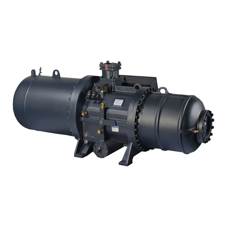
Hanbell RC2-D User manual

RC2-D Technical Manual
Content
1. OverView...................................................................................................................................4
1.1 Nomenclature................................................................................................................. 4
1.2 Product feature...............................................................................................................4
1.3 Nameplate ......................................................................................................................4
2. Specification..............................................................................................................................5
2.1 Specification parameters ................................................................................................5
3. Capacity control system............................................................................................................6
3.1 Compression process......................................................................................................6
3.2 Step capacity control system ..........................................................................................6
4. Electrical parameters and design............................................................................................11
4.1 Start-up .........................................................................................................................11
4.2 Start-up limit.................................................................................................................12
4.3 MCC&LRA...................................................................................................................... 13
4.4 Wiring diagram of terminal cover plate .......................................................................14
4.5 Grounding.....................................................................................................................14
5. Accessories..............................................................................................................................16
5.1 Standard Accessories and Optional Accessories...........................................................16
5.2 Accessories Introduction ..............................................................................................17
6. Lubricating oil..........................................................................................................................30
6.1 Lubricant configuration ................................................................................................30
6.2 Pre-cautions for changing oil........................................................................................31
6.3 The Replacement of Lubricanting oil............................................................................31
7. System Application .................................................................................................................32
7.1 Principle& Application of economizer ..........................................................................32
7.2 Application of pressure maintaining valve ...................................................................33
7.3 Application of parallel connection system....................................................................34
7.4 Discharge temperature control - oil cooler application ...............................................34
7.5 Motor temperature control - Application of liquid injection .......................................36
7.6 Key points for compressor application ......................................................................... 37
8. Operation and Maintenance...................................................................................................38
8.1 Compressor Installation................................................................................................38
8.2 Compressor maintenance.............................................................................................41
9. Operation Range .....................................................................................................................44
10. Appearance Drawing............................................................................................................... 46
10.1 RC2-100~930D-S Drawing ............................................................................................ 46
10.2 RC2-100~930D-P Drawing ............................................................................................51
11. Connector Size ........................................................................................................................56
11.1 Connector size of single model ....................................................................................56
11.2 Connector size of model in parallel connection........................................................... 57
RC2-D Technical Manual
1. OverView
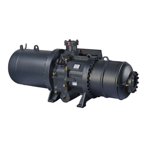
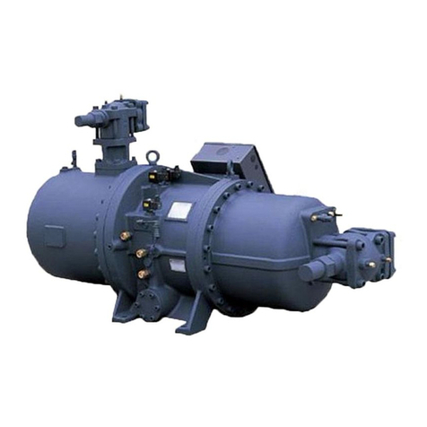
RC2-D is a special single-stage screw compressor which is specially developed for the use characteristics of the
refrigeration market. This series are suitable for various refrigeration applications including high, medium and
low temperature. Compared with the previous generation products, RC2-D series have higher reliability and
operation efficiency.
This technical manual covers the operation, dimensions, installation, accessories, application and basic
troubleshooting of the compressor. It is recommended to read this technical manual carefully before designing,
installing, operating and maintaining the compressor to avoid unnecessary damage to the compressor.
1.1 Nomenclature
RC2 - XXX - X - X - X
Product code: Displacement: Motor Oil separator Application
RC2 series 50m3/h Version D Null: Standard M: High temp
S: Single L: Low temp
P: Parallel connection
1.2 Product feature
High performance
With stop valve of the economizer, the design of the economizer connector is optimized to improve the
performance of the economizer. Motor temperature sensor and the throttle mechanism are adopted to
reduce the influence of the motor liquid injection on the system performance.
Stable and reliable
Optimized motor cooling channel design comprehensively reduce the motor temperature, improve the
safety margin; upgrade the capacity control mechanism, use more superior sealing materials, further
improve the capacity adjustment stability.
Product segmentation
The whole series is subdivided into M series and L series, of which M series can meet the application
needs of high temperature refrigeration, and L series can meet the application needs of medium and low
temperature refrigeration.
1.3 Nameplate

RC2-D Technical Manual
2. Specification
2.1Specification parameters
Model
Compressor
Motor
Lubricant
O il heater
Pressure
test
Weight
Displacement
50Hzm3/h
Rotation
50Hz r/min
Capacity
Control
(100%)
type
Start-up
Voltage
(V)50Hz
Insulati
on
Protecti
on
Step
L
W
Bar
kg
RC2-100D-S(P)
98
2950
33,66,
100
3-phase 2-pole squirrel cage induction motor
Y-△
380
Level F
PTC
7
300
35
275/270
RC2-140D-S(P)
137
7
280/275
RC2-180D-S(P)
180
7
300/330
RC2-200D-S(P)
193
25,50,75,100
8
420/410
RC2-230D-S(P)
230
14
540/520
RC2-260D-S(P)
257
14
545/525
RC2-300D-S(P)
293
16
590/570
RC2-310D-S(P)
308
14
575/555
RC2-340D-S(P)
339
16
600/580
RC2-370D-S(P)
366
16
610/590
RC2-410D-S(P)
407
15
730/700
RC2-470D-S(P)
471
18
800/770
RC2-510D-S(P)
508
20
760/730
RC2-550D-S(P)
549
23
820/790
RC2-580D-S(P)
583
20
805/775
RC2-620D-S(P)
619
23
850/810
RC2-710D-S(P)
713
28
1099/1059
RC2-790D-S(P)
791
28
1140/1100
RC2-830D-S(P)
825
28
1150/1420
RC2-930D-S(P)
929
28
1180/1140
Note: DP series are for application of parallel connection. There are not lubricants in the compressor.

RC2-D Technical Manual
3. Capacity control system
3.1 Compression process
At the beginning of the compression cycle, as the male rotor and female rotor unmesh, gas from suction
port fills the interlobe space (refer to the dark area in Figure 3-1). Refrigerant at suction pressure
continues to fill it, until the trailing lobe crosses the suction area and the gas is trapped inside the
interlobe space. As the male rotor and female rotor meshes, the interlobe space moves towards to
discharge end and its volume decreases so that gas pressure increases consequently. Gas is discharged
from the interlobe space when the leading lobe crosses the discharge port whose volume ratio is
designed differently for various applications.
(A)Suction and sealing (B)Compression (C)Discharge
Figure 3-1 Compression process
3.2 Step capacity control system
RC2-D series screw compressors are equipped with either 3&4-step capacity control system.
This capacity control systems consist of slide valve, piston rod, piston cylinde and piston ring.
The slide valve and the piston are connected by a piston rod; the oil pressure in the system
pushes the piston in the cylinder to move, thus the slide valve moves .
Step capacity control, as shown in Figure 3-2.
The lubricating oil flows out of the oil tank and
passes through the oil filter and capillary tube.
As the oil pressure is higher than the sum of
the right end spring force and the refrigerant
pressure, the lubricating oil enters the piston
cylinder. Under the action of pressure
difference, the piston moves to the right, the
effective compression volume in the
compression chamber increase. At this time, the discharge volume of refrigerant gas increases,
resulting in the increase of refrigeration capacity. However, when any one of the step (3-stage
/ 4-stage) capacity control solenoid valves is energized, the high-pressure oil in the piston
Figure 3-2 (3&4 step) Capacity control

RC2-D Technical Manual
cylinder bypasses to the suction side, causing the piston and slide valve to move to the left
and part of the refrigerant gas bypasses the suction port from the compression chamber. At
this time, due to the reduction of refrigerant discharge, resulting in the reduction of
refrigeration capacity. The piston spring is used to push the piston back to its starting position.
If the compressor is started under full load, it will generate over-current start-up. Therefore, in
order to reduce the start-up current of the next start-up, the slide valve should be unloaded to
the minimum load position during shutdown.
3.2.13 or 4 Step Capacity control system
The compressor is equipped with two solenoid valves (RC2-100, RC2-140 and RC2-180) or three
solenoid valves (other models). They can control the capacity of the compressor from the
minimum capacity to the full load state (100%). These two / three normally closed (NC)
solenoid valves are used to control the required capacity.When the compressor with a 3 / 4
step capacity control system, the compressor is loaded through 33% - 66% to 100% or 25% -
50% - 75% to 100% process, and the
compressor is unloaded through 100% -
66% - 33% or 100% - 75% - 50% to 25%
process. If needs to operate under 25%
loading for long time, oil return, motor
cooling and high discharge temperature
should be considered. For example, the
motor is cooled by liquid injection and
the lubricating oil is cooled by external
oil circuit。
Figure 3-3 (3&4 step) Capacity control
No.
Part Name
No.
Part Name
1
Suction filter
10
Lubricanting oil
2
Suction gas
11
Oil separator filter
3
Motor
12
Discharge gas
4
Oil filter
13
Capillary
5
Suction bearing
14
Solenoid valve(25%/33%)
6
Male rotor
15
Solenoid valve(50%/66%)
7
Discharge bearing
16
Solenoid valve(75%)
8
Muffler tube
17
Sliding valve
9
Discharge gas
*
RC2 -100~180 only with
33%/66%
25%/33%
75%
50%/66%

RC2-D Technical Manual
3.2.1.1 25% (33%) loading
When the compressor starts, the solenoid
valve is activated, and the piston is in the
25% (33%) load position. In this state, the
high-pressure oil from the oil tank is
continuously injected into the piston cylinder
through the capillary, and the high-pressure
oil in the piston cylinder is directly bypassed
to the suction port, so the piston remains in
its initial position.
Note: Activate the SV1 (25%) for 1 ~ 3 minutes before starting the compressor, so that the sliding
valve is at the minimum load before start-up, so as to avoid the trip protection caused by large current
when the motor is started.After the start-up process, do not run the compressor for a long time under
25% load, but directly load the compressor (especially in the case of large differential pressure /
pressure ratio) to prevent the compressor discharge temperature from being too high.
3.2.1.2 50% (66%) loading
When the 50% / 66% solenoid valve is activated, the high-pressure oil from the oil tank flows into the
piston cylinder and pushes the piston to move to the right. When it moves to 50% / 66%, the
high-pressure oil flows back from the oil unloading hole to the suction port through 50% / 66%, so the
piston stops running at this position and the compressor remains at 50% / 66% load state.
3.2.1.3 75% loading (RC2 -100~RC2 -180 without this loading state)
When 75% solenoid is activated, and the 50% solenoid valve is off, the high oil pressure pushes the
piston to move to the right. When the valve moves to 75%, the high pressure oil flows back to the
suction port through 75% of the oil hole, so the piston stops running in this position and the compressor
is kept at 75% load state.
3.2.1.4 100% loading
When all the solenoid valves are off, the high oil pressure continuously flows into the piston cylinder
and gradually pushes the piston to move to the suction side. When the sliding valve contacts the dead
center of the compression chamber, the piston also reaches its dead center position. At this time, there
is no compressed gas bypass, the compressor reaches full load.
RC2 -100、140、180
33% (NC)
66% (NC)
100% loading
N
N
66% loading
N
Y
33% loading
(Start/ Stop)
Y
N
RC2 -200~1530
25% (NC)
50% (NC)
75% (NC)
100% loading
N
N
N
75% loading
N
N
Y
50% loading
N
Y
N
25% loading
(Start/ Stop)
Y
N
N

RC2-D Technical Manual
Figure 3-4 25% 、50%、75%、100% Loading schematic diagram
◎Note: ON: the solenoid valve is activated; OFF: the solenoid valve is not activated
3.2.2Continuous loading of compressor
Since it will take a long time for compressor to reach the required working conditions, the compressor
shall be started at 25% or 33% loading and kept for about 30 seconds (the startup time length
recommended by Hanbell). Then the compressor is gradually loaded to 50% (66%) in time "t" and then
loaded to 75% in another"t" time. The time "t" is determined according to different working conditions
and application conditions.
Figure 3-5 Continuous loading time chart of compressor

RC2-D Technical Manual
Figure 3-6 Diagram of outlet water temperature and capacity control
Please refer to the chapter of capacity control system for specific information. If you need special
capacity control system, please contact Hanbell directly.

RC2-D Technical Manual
4. Electrical parameters and design
4.1Start-up
The standard startup mode of Hanbell RC2-D series screw compressor is Y-Δ startup.
1)Y-Δstart-up
Y-Δ connection mode is Y shape connection when start-up. At this time, the voltage on the winding is
reduced to 1/ 3 of the input voltage. After the start-up, re-connect to the delta shape. By this starting
model, we can reduce the starting current by the reducing the starting voltage, which is also called
step-down start.
Figure 4-1 Y-Δ Connection diagram
Note: After the Y - shape startup, the MCM & MCS conversion takes 0.25 seconds, and the MCM
& MCD gets the power to conduct the delta operation. In 0.25 seconds, it may cause pseudo short
circuit due to improper contactor action, resulting in compressor jumping. When this happens, it is
recommended to use an adjustable Y-Δtime relay or delay device to extend the conversion of
MCM and MCD, and the power gain time is about 0.25 to 0.5 seconds. Please refer to the Y-Δ
Conversion Time Diagram for specific information.
In Y-connection, MCM and MCS are electrified to make Z, X and Y become the center of Y
connection. After a few seconds (3-5 seconds recommended), the MCM and MCS are disconnected.
After about 0.25 seconds, the MCM and MCD are powered on, and at this time, they are converted
to Δshape connection. Y-Δconversion time diagram is shown in Figure 4-2.

RC2-D Technical Manual
Figure 4-2 Y-Δconversion time diagram
2)Y-Δ startup features
The starting current of Y shape connection is 1/3 of the locked rotor ampere. The starting torque
of Y shape connection is 1/3 of the locked rotor torque.
The rotating acceleration of the electrode is reduced when the overload starts, so the compressor
needs to start with light load.
Note: In addition to Y-Δ startup, if there is a need of soft start or reactance step-down start, please
contact Hanbell for further information.
4.2Start-up limit
Hanbell compressor is started by Y-Delta, and the compressor must be at the lowest load when starting.
1)Compressor start-up
RC2-100D~580D compressor should not start more than 6 times per hour, and RC2-620D~930D
compressor should not start more than 4 times per hour.
When starting, the compressor should be at the lowest load (25% or 33%).
In case of low ambient temperature, the oil heater must be powered on and heated 6 hours before
the compressor start to maintain the oil temperature.
When starting, Y connection time is generally 4±1 s, and the max allowable time of Y switching to
△connection is 40ms. The actual Y–△conversion time can be adjusted according to the actual
working conditions on site, the longest Y–△conversion time is no more than 7 seconds.
When starting, the power supply voltage shall not exceed ±10% of the rated voltage.
2)Power limit
Long-term operation: Rated voltage ±5%.

RC2-D Technical Manual
Instantaneous operation: Rated voltage ±10%.
Frequency: Rated frequency ±2%.
Unbalanced voltage of each phase: ± 1%.
Note: An additional high&low voltage protector shall be set up in the unstable voltage area.
Setting the rated voltage within the range of ± 5% can ensure the safe and long -term
operation of the compressor.
3)Unbalanced voltage
Voltage unbalance is usually caused by load change. When the load of each phase is different, voltage
unbalance will appear which may cause serious damage to the motor. NEMA is defined as voltage
unbalance as follows:
Voltage unbalance =
Difference between average voltage and maximum
voltage in three phase voltage
*100%
Average voltage
According to NEMA, the best operation condition of multiphase motor is that the voltage unbalance of
motor is not more than 1%. In addition, it is recommended not to start the motor when the voltage
imbalance exceeds 5%, which may cause serious damage to the motor.
4)Contactor selection
Please select the appropriate contactor according to AC3 specification, compressor selection program
and system design status.
5)Grounding requirements
There is a grounding connector in the wire box, please connect it to the grounding terminal of the
system control panel accurately.
Note:
A. The setting value of normal leakage protector should be higher than 50mA; In humid environment,
25mA is better.
B. The grounding voltage shall not exceed 50V; not exceed 25V in humid environment
C. The grounding resistance should not exceed 500Ω.
D. Air circuit breaker is usually equipped with electronic leakage protection; please refer to the relevant
settings to ensure its normal operation.
E. If the electronic leakage protector alarm, please check whether the insulation device is normal and
whether its circuit and setting are correct. Please make sure there is no error before turning on the power.
If there is any problem, please contact the equipment supplier.
4.3MCC&LRA
Starting current definition (LRA): add rated frequency, and rated voltage to the motor coil, block or
restrain the motor rotors so that the motor cannot rotate, the current of the motor at this time is called
the starting current (also known as locked rotor ampere).

RC2-D Technical Manual
Maximum operating current definition (MCC): maximum load current of compressor motor running.
Motor: Mainly used for R22, R404A, and R507 refrigerant
Frequency: 50Hz; Voltage: 380V
Model
MCC(A)
LRA(A)
Model
MCC(A)
LRA(A)
RC2-100D-S(P)
55
245
RC2-410D-S(P)
208
740
RC2-140D-S(P)
72
330
RC2-470D-S(P)
245
840
RC2-180D-S(P)
91
490
RC2-510D-S(P)
250
840
RC2-200D-S(P)
99
490
RC2-550D-S(P)
280
925
RC2-230D-S(P)
119
510
RC2-580D-S(P)
300
925
RC2-260D-S(P)
129
510
RC2-620D-S(P)
317
1295
RC2-300D-S(P)
148
645
RC2-710D-S(P)
360
1410
RC2-310D-S(P)
157
645
RC2-790D-S(P)
382
1510
RC2-340D-S(P)
174
730
RC2-830D-S(P)
429
1640
RC2-370D-S(P)
188
780
RC2-930D-S(P)
491
2090
Table 4-1 RC2-D series compressor MCC&LRA
Note: MCC in table 4-1 above will vary depending on voltage and frequency.
4.4Wiring diagram of terminal cover plate
4.5Grounding
There is a ground wire connector in the terminal box. Please make sure it is connected with the ground
wire.
Note:
a. The setting of leakage protector should be more than 50mA; In humid area, the setting should be
changed to 25mA

RC2-D Technical Manual
b. The grounding voltage of terminal box shall not be greater than 50V; in humid area, it should be 25V.
c. The grounding resistance shall not be greater than 50Ω.
d. Air cut board (ACB) is usually connected with leakage protector. Please refer to relevant operation
settings.
e. Once the leakage protection is started, please check if the insulation is normal and if the circuit and
setting are correct. Please turn on the power after confirmation. If you have any questions, please
contact the equipment supplier.
Specification for terminal plate nut
Model
Specification
Torque(N.m)
RC2 -100~180D-S(P)
M8
20
RC2 -200~930D-S(P)
M12
35
Note: when the surface temperature of compressor is lower than the air dew point
temperature, it is recommended to wrap the exposed part of the wiring with electrical
insulation tape to improve reliability

RC2-D Technical Manual
5. Accessories
In order to provide customers with an overall solution, Hanbell design standard accessories and optional
accessories according to different application requirements, to ensure that the compressor can be safe,
stable operation, and achieve the highest efficiency.
5.1Standard Accessories and Optional Accessories
Accessories list
●
Standard
△
Optional
Item
Part name
Qty
Parallel
application
Single
application
1
Discharge stop valve
1
●
●
2
Discharge check valve
1
●
●
3
Suction stop valve
1
●
●
4
Suction check valve
1
△
△
5
ECO stop valve
1
●
●
6
Liquid injection controller
1
△
△
7
Suction& discharge bushing
1 set
●
●
8
Damping pad
4
●
●
9
Oil circuit solenoid valve
1
●
△
10
External oil filter
1
●
△
11
Oil flow switch
1
●
△
12
Oil sight glass
1
●
△
13
External oil filter differential
pressure monitoring switch
1
●
●
14
Protection module
1
●
●
15
Discharge temp sensor
1
●
●
16
Motor coil temp sensor
1
●
●
17
Oil level switch
/
△
●
18
Pressure maintaining valve and
bushing
1 set
△
△
19
Lubricanting oil
/
△
●
20
300W Oil heater
1
△
●

RC2-D Technical Manual
5.2Accessories Introduction
Hanbel compressor is equipped with a series of accessories; the
following are described in details.
5.2.1 Suction& Discharge bushing
RC2-100~930D-S suction and discharge flange, bushing configuration
Model& Flange
Size
Material& Size
Dimension
φA
φB
φC
φD
φE
RC2-100~RC2-200 Discharge flange
1-1/2”
Copper
1- 5/8”
52
75
35
42
52
Steel
1- 1/2”
49.3
64
RC2-100,RC2-140 Suction flange
RC2-230~RC2-310 Discharge flange
2”
Copper
2- 1/8”
50
90
30
55
65
Steel
2”
61.3
74
RC2-180,RC2-200 Suction flange
RC2-340~RC2-470 Discharge flange
2-1/2”
Copper
2- 5/8”
60
110
35
68
77
Steel
2- 1/2”
77.2
90
RC2-230~RC2-310 Suction flange
RC2-510~RC2-620 Discharge flange
3”
Copper
3- 1/8”
66
120
45
80.5
90
Steel
3”
90.2
103
RC2-340~RC2-580 Suction flange
RC2-710~RC2-930 Discharge flange
4”
Copper
3- 5/8”
76
145
50
93
103
Steel
4”
110
128
RC2-620~RC2-930 Suction flange
5”
Copper
4- 1/8”
80
174
35
106
121
Steel
5”
75
135
154
Note: The above specification is for standard RC2-D series compressor (D-S type), If need non-standard
bushing, please confirm with hanbell.
RC2-100~930D-P suction and discharge flange, bushing configuration
Model& Flange
Size
Material& Size
Dimension
A
B
C
D
E
RC2-100,RC2-140 Suction flange
RC2-100 ~RC2-200 Discharge
flange
2“
Copper
2- 1/8”
50
90
30
55
65
Steel
2”
61.3
74
RC2-180,RC2-200 Suction flange
RC2-230 ~RC2-370 Discharge
flange
2-1/2”
Copper
2- 5/8”
60
110
35
68
77
Steel
2- 1/2”
77.2
90
RC2-230~RC2-310 Suction flange
RC2-410 ~RC2-580 Discharge
flange
3”
Copper
3- 1/8”
66
120
45
80.5
90
Steel
3”
90.2
103
RC2-340~RC2-580 Suction flange
RC2-620 ~RC2-930 Discharge
flange
4”
Copper
3- 5/8”
76
145
50
93
103
Steel
4”
110
128
RC2-620~RC2-930 Suction flange
5”
Copper
4- 1/8”
80
174
35
106
121
Steel
5”
75
135
154
Note: The above specification is for standard RC2-D series compressor (D-P type), If need non-standard
bushing, please confirm with hanbell.

RC2-D Technical Manual
5.2.2 Suction& Discharge stop valve
In order to facilitate the maintenance and repair of the compressor, it is recommended to install the
suction and discharge stop valve. Please refer to the following table for the Hanbell shutoff valves.
D-S Type
Model
Suction
Discharge
Model
Suction
Discharge
RC2-100
2”
1-1/2”
RC2-410
4”
2-1/2”
RC2-140
2”
1-1/2”
RC2-470
4”
2-1/2”
RC2-180
2-1/2”
1-1/2”
RC2-510
4”
3”
RC2-200
2-1/2”
1-1/2”
RC2-550
4”
3”
RC2-230
3”
2”
RC2-580
4”
3”
RC2-260
3”
2”
RC2-620
5”
3”
RC2-300
3”
2”
RC2-710
5”
4”
RC2-310
3”
2”
RC2-790
5”
4”
RC2-340
4”
2-1/2”
RC2-830
5”
4”
RC2-370
4”
2-1/2”
RC2-930
5”
4”
D-P type
Model
Suction
Discharge
Model
Suction
Discharge
RC2-100
2”
2”
RC2-410
4”
3”
RC2-140
2”
2”
RC2-470
4”
3”
RC2-180
2-1/2”
2”
RC2-510
4”
3”
RC2-200
2-1/2”
2”
RC2-550
4”
3”
RC2-230
3”
2-1/2”
RC2-580
4”
3”
RC2-260
3”
2-1/2”
RC2-620
5”
4”
RC2-300
3”
2-1/2”
RC2-710
5”
4”
RC2-310
3”
2-1/2”
RC2-790
5”
4”
RC2-340
4”
2-1/2”
RC2-830
5”
4”
RC2-370
4”
2-1/2”
RC2-930
5”
4”
5.2.3 Suction check valve
Check valve is a kind of valve which can automatically prevent the backflow of fluid. The disc of the check
valve opens under the action of fluid pressure, and the fluid flows from the inlet side to the outlet side.
When the pressure on the inlet side is lower than that on the outlet side, the valve disc will automatically
close under the action of fluid pressure difference to prevent fluid backflow.
Specification
Dimension
Nut
Max working pressure
A
B
C
2”
Φ90
85
Φ102
M16*200
28bar
2-1/2”
Φ110
97
Φ122
M16*230
3”
Φ120
108
Φ138
M20*280
4”
Φ145
123
Φ163
M20*320
Spec.
Dimension
Max working pressure
A
B
φC
φD
E
1-1/2”
115
263
75
18
M16X2
28 Bar
2”
131
284
90
18
M16X2
2-1/2”
147
289
110
18
M16X2
3”
177
351
120
22
M20X2.5
4”
209
407
145
22
M20X2.5

RC2-D Technical Manual
5.2.4Horizontal discharge check valve
The horizontal discharge check valve is a standard accessory of RC2 - DP compressor. Considering the
limited installation space, horizontal discharge check valve can replace gravity check valve for RC2 - DP
compressor. The specification and installation diagram of horizontal check valve are as follows::
Specification
Dimension Unit:mm
Max working pressure
φA
B
φC
φD
Nut
2”
90
85
102
91
16*140
28 Bar
2-1/2”
110
97
122
111
16*150
3”
120
109
138
121
20*170
4”
145
125
163
146
20*190
5”
175
150
203
176
M20*200
5.2.5 Gravity check valve
Gravity check valve can automatically prevent the backflow of fluid. The valve disc opens under the
action of fluid pressure, and the fluid flows from the inlet side to the outlet side. When the pressure at
the inlet side is lower than that at the outlet side, the valve disc will automatically close under the action
of fluid pressure difference, gravity and other factors to prevent fluid backflow.

RC2-D Technical Manual
Size
A
B
C
D
E
F
G
H
Max working pressure
1.5”
109
16
76
75
20
99
18
60
28 Bar
2”
122
16
91
90
20
104
18
70
2.5”
134
16
111
110
25
119
18
90
3”
153
20
121
120
25
129
22
100
4”
171
20
146
145
25
129
22
125
5.2.6 Economizer stop valve
Economical stop valve for RC2-D is optional. The specific type and installation are as follows:
Installation diagram
5.2.7 Pressure maintaining valve
The pressure maintaining valve enables the compressor to quickly establish enough high and low
pressure difference within a short period of time after starting up, so as to ensure the smooth loading of
the compressor and ensure that the compressor will not be adversely affected by oil loss.
Size
A
B
C
D
E
F
Model
7/8
131.5
11
46
22.3
89.3
124
RC2-100~RC2-180D-S/P
7/8
131.5
11
46
22.3
76.3
111
RC2-200~RC2-260D-S/P
1 1/8
138.5
13
54
28.2
76.8
111
RC2-300~RC2-510D-S/P
1 3/8
186
13
61
35.2
82.7
119
RC2-550~RC2-710 D-S/P
1 3/8
186
13
61
35.2
96.3
133
RC2-790~RC2-930D-S/P

RC2-D Technical Manual
5.2.8 Protection Module
5.2.8.1 INT69 HBY Diagnose protection module
Application:
The protection module INT69 HBY Diagnose is the advanced product of the protection module series,
which is used for the compressor protection microcontrollers. The flexible response function is added in
the phase sequence monitoring, which improves the practicability and prolongs the life of the
refrigeration system. INT69 HBY Diagnose automatically stores work and error data in a memory. Only
through a specific transmission line, the data can be read on a personal computer and be used for
diagnostic analysis.
Function:
The PTC thermistor in series enters the signal input end of the protection module.
If any resistance value of the thermistors rises above the jump off value, the protection module will
jump off. The blocking value of PTC will reduce to the reset value. After 5 minutes of reset time, the
module will automatically reset. In the first disconnected 24 hours, if the PTC values rise to the reset
value again, the reset time will be 60 minutes. If the PTC third time rise to the reset value in 24
hours, the module will be locked and cannot be reset automatically.
One second after the motor starts, the motor phase monitoring function will be activated and remain
to be activated for 5 seconds. Motor phase being abnormal or motor being under-phase will cause
the protection module to be disconnected and locked.
In order to avoid the tripping caused by reversal after the compressor shutdown, the phase
monitoring function will only maintain for 20 seconds after the motor is stopped.
LED (Red / Green / Orange) shows its working information.
The motor protection module cannot be used in the variable frequency drive device.
The PTC short circuit will cause deadlock, and the short cycle will lead to the reset delay.
If the reset delays when the temperature reduces or the error is removed, please reset the module.
The compressor needs to be restarted after the reset.
This module must be assembled and maintained by a professional electrician. It should have
European or national standards. When the module is connected to electrical equipment and cooling
devices the connection line between the terminal box and the temperature sensor must be the
insulation line.
Size
A
B
C
D
E
F
G
H
Pressure loss
Max working pressure
Opening pressure difference
1.5”
235
93
119
76
109
M16
75
18
<0.1
Bar
30
Bar
3.6
±0.3
Bar
2”
247
105
126
91
122
M16
90
18
2.5”
300
110
136
111
134
M16
110
18
3”
364
122
156
121
153
M20
120
22
4”
413
165
166
146
171
M20
145
22

RC2-D Technical Manual
Technical data:
Item
Technical data
Item
Technical data
Supply voltage
AC 50/60HZ 115/240V±10% 3VA
System PTC short
circuit monitoring
Normally <30Ω
Motor voltage
3 AC 50/60Hz 200/690V ±10%
Over frequency
operation
Not support
—Sensor type
—R25, All
—Maximum
connection
length
Connect 1-2 AMS sensors and 1-9 PTC
in serial as optional; serial connection
shall meet the DIN 44081 and DIN
44082 standards.
<1.8KΩ
30M
—Motor static jump
off
1 times/24h
2 times/24h
3times/24h
—Switching
frequency
—Phase stagger
—Phase loss
Cancel deadlock or
reset delay
5min±1min
60min±12min
Deadlock
5min±1min
Deadlock
Deadlock
Power off and reset
Ambient
temperature
-30…70℃
Max switching
frequency
Switch for 3 times
within 30s
Phase monitor
—Phase sequence
—Phase loss
—Inactivation
Activated 1 second after the motor
starts and will remain monitoring for 5
seconds;
Activated 1 second after the motor
starts and will remain monitoring till
the machine stops;
About 20 seconds after the motor
stops.
Delay reset relay
—Power
—Mechanical lifetime
AC 240V 2.5A C300 at
least AC/DC 24V 20mA
One million times on
and off switching
Signal light flashing:
The signal light is for convenient, fast and easy maintenance; the signal is composed of red and orange.
The current state of light flashing depends on the number of pulse flashes.
Signal is as below:
Pause 1 time RED Pause twice Orange Pause 1 time
(Pause flash: 1-5times) (Pause flash: 1-5times)
Description
Green
Compressor on standby
Green flash
Compressor operation
Red/ Organ flash
Faults occur; relay jump off; compressor stop; please
refer to sticker to solve the faults.
Table of contents
Other Hanbell Air Compressor manuals

Hanbell
Hanbell RC2 Series User manual

Hanbell
Hanbell RC2-F Series User manual

Hanbell
Hanbell RC2-AVI Series User manual

Hanbell
Hanbell RC2-100A User manual

Hanbell
Hanbell SAM-285 User manual

Hanbell
Hanbell LBII-PLUS User manual

Hanbell
Hanbell LT-S Series User manual

Hanbell
Hanbell RT Series User manual

Hanbell
Hanbell RC2 Series Installation manual
Popular Air Compressor manuals by other brands

Clarke
Clarke BOXER II 14/100P Operation & maintenance instructions

HDX
HDX VSP0000201.HDX1 Use and care guide

Sears
Sears Craftsman 919.184260 owner's manual

Gardner Denver
Gardner Denver PUREAIR EWD99E Operating and service manual

Quincy Compressor
Quincy Compressor QGD 40 Instruction book

Metabo
Metabo Mega 350 D parts list