Handler Red Wing 16B User manual

WARNING!
FOR YOUR SAFETY PLEASE READ INSTRUCTIONS
BEFORE OPERATING TOOL & WEAR EYE PROTECTION
16B RED WING LATHE & CHUK/CHANGER
OPERATING MANUAL
IMPORTANT INSTRUCTIONS
[06/2009]
FD.06/2009

16B Red Wing Lathe & Chuk/Changer Instruction 2
Thank you for purchasing a HANDLER’s Red Wing Lathe.
Open the carton and inspect all contents. Your 16B was inspected several times
during the manufacturing process, plus as a completed unit after it was built and
tested.
Should damage have occurred, please contact the freight forwarder, immediately.
Failure to contact the freight forwarder, immediately, will result in the loss of your
rights to place a claim for possible external or internal damage.
After you have contacted the freight forwarder, please contact your distributor
advising that you have received a unit which sustained damage, detailing the
possible damage and requesting they contact Handler. Possible damage MUST
BE CLAIMED by the receiver of the product, not the sender.
RED WING MOTOR
Your Red Wing has been inspected prior to being shipped. Open the package and
inspect its contents. Should damage have occurred in transit, contact the freight
forwarder immediately. Do not contact Handler as the receiver of a product must
file a claim for damage within 14 days. Failure to file a claim in a timely manner
could result in the loss of your rights of recovery. Should you require assistance,
please contact Handler Manufacturing at: 1-908-233-7796 or 1-800-274-2635
CAUTION!
BEFORE Connecting and Operating!
Unpack Accessories from Unit
For Your Protection EXAMINE THE GOODS.
THANK YOU FOR PURCHASING A HANDLER PRODUCT

16B Red Wing Lathe & Chuk/Changer Instruction 3
WARNING!
SAFETY INSTRUCTIONS!
WARNING FOR YOUR SAFETY:
READ INSTRUCTIONS BEFORE
OPERATING TOOL.
WEAR EYE PROTECTION!
ALL ELECTRICAL ITEMS WITH A CORD SET:
REPAIR OR REPLACE DAMAGED
OR WORN CORD IMMEDIATELY.
DO NOT ExPOSE TO RAIN OR USE IN
DAMP LOCATIONS.
ADVERTISSEMENT:
NE PAS ExPOSER A LA PLUIE
ET NE PAS UTILISER DANS LES
EMPLACEMENTS HUMIDES.

16B Red Wing Lathe & Chuk/Changer Instruction 4
CHUCK REMOVAL INSTRUCTIONS
Remove the lathe from the carton and place it in a suitable location on a sturdy horizontal surface.
The unit must be bolted to the table top. Bolting the unit securely to a solid table top will prevent
possible lathe movement during operation and possible operator injury.
Plug the lathe’s cord set into a grounded 115 Volt/60 Hz electrical socket only. Do not utilize a
3-2 prong adapter. Failure to plug the lathe into a properly grounded receptacle may result in
operator injury. Your lathe is now ready for operation with the aid of chucks placed on the shaft (see
instructions).
The No. 26, 26A, 26L, and 28H lathes are constructed to function on two speeds. Low speed is
1725 RPM and high speed is 3450 RPM. The lathe shaft is provided with special dental tapered
shafts which will accept chucks which fit onto a tapered shaft only. The models 27, 29, & 29A are
built to function at 3450 RPM. NOTE: if you have specified that your lathe should contain 1/2” straight
shafts, only chucks which contain a 1/2” arbor hole will adapt to these shafts.
The polishing motor with a tapered shaft is provided with a left and right chuck remover (see figure
No. 1). By pulling upward toward the front of the lathe, the chuck remover will unscrew outward to
“push” the chuck from the tapered shaft. Various types of chucks and chuck accessories are utilized to
perform different types of grinding and polishing operations with your lathe. These are attached to your
lathe’s shaft via a friction fit.
TO PLACE A CHUCK ONTO THE SHAFT OF YOUR LATHE, PLEASE FOLLOW THESE INSTRUCTIONS:
1. Make certain both the lathe’s shaft and the arbor hole of the chuck to be placed onto the shaft are
clean of any dust and debris. Be certain the chuck remover on each side is in place.
2. With the lathe turned “OFF”, place the chuck onto the right or left shaft of your lathe. DO NOT
place a chuck labeled “R” or “L” on the opposite shaft. (See Instructions on following page.)
3. Push the chuck onto the shaft as far as it will go. Since the chucks fit onto tapered shafts via
friction fit, make certain the chuck is placed securely on the lathe shaft. It may be necessary to
tap the end of the chuck onto the lathe shaft with the aid of a soft rubber, plastic or leather
mallet. Do not use a metal hammer or mallet as this will damage the chuck.
4. After the chuck has been placed securely on the lathe shaft, place the buff, brush, abrasive
wheel, bur or mandrel onto the chuck. Secure this in place as per the manufacturers suggestions.
5. Turn the lathe on and make certain the accessory which has been placed on the lathe chuck is
securely in position. If either the chuck or accessory have not been secured to the lathe shaft,
secure it now.
NOTE: Many Red Wing polishing motors are shipped with 1/2” straight shafts. Chucks used on Red
Wing Polishing motors equipped with a 1/2” straight shaft utilize a set screw to hold the chuck in
position. Make certain to tighten this securely.
FIGURE 1
PUSH ON AND TAP IN PLACE
CHUCK
REMOVER
TURN MOTOR OFF
PULL HANDLE UPWARD TO REMOVE CHUCK

16B Red Wing Lathe & Chuk/Changer Instruction 5
IMPORTANT NOTICE
Adjusting Chuk/Changer to Tension Collets
The alignment of the Chuk/Changer to the clutch will alleviate slipping clutch noise prob-
lems and tension collets. Please follow the instructions, below, to alleviate these problems.
1. Remove the plug which connects the lathe from the electrical source.
2. Move the activating handle on the Chuk/Changer to the six o’clock (open collet)
position as seen in diagram 1.
3. Loosen the top set screw and the two lower set screws, which are found on the
2-1/2” adapter, which hold the Chuk/Changer onto the lathe.
4. Place your left hand on the left hand side of the lathe and your right hand on the
nose section of the Chuk/Changer, and push the Chuk/Changer in toward the lathe
as far as it will go. It will move approximately 1/32-1/16 of an inch inward toward
the lathe.
5. Holding the Chuk/Changer in your right hand, move the activating handle clockwise
to the 9:30- 10:00 o’clock position. The Chuk/Changer will move outward, slightly.
Tighten the three set screws on the adapter which were previously loosened, holding
the Chuk/Changer in position as seen in diagram 2.
NOTE: If you have another person available to assist you in this short procedure,
ask them to tighten the set screws. If you do not, make certain that you hold the Chuk/
Changer inward toward the lathe when you tighten the set screws on the adapter.
This should alleviate the squeaking-grinding noise you are hearing by the lathe Chuk/
Changer combination and place proper tension on collets.
REMEMBER: Clean collets every 30 days.
Your Chuk/Changer has been manufactured, assembled, adjusted and tested with the
utmost of care to insure that you will receive it in perfect condition. We ask that you
carefully read and follow these step by step instructions.

16B Red Wing Lathe & Chuk/Changer Instruction 6
CHUK/CHANGER INSTALLATION
REMOVE CHUCK REMOVER
1/16”
2-1/2”
1. Use small washers if necessary
to maintain clearance between
clutch hub and lathe housing.
2. Line up set screw
with flat on 1/2” shaft
and tighten securely.
Slide Chuk/Changer with
adapter onto motor hub
and secure in place with
set screws on adapter.
Normal running position will
vary according to amount of
lathe end play.
Never move handle to
running position WITHOUT
a tool in the collet.
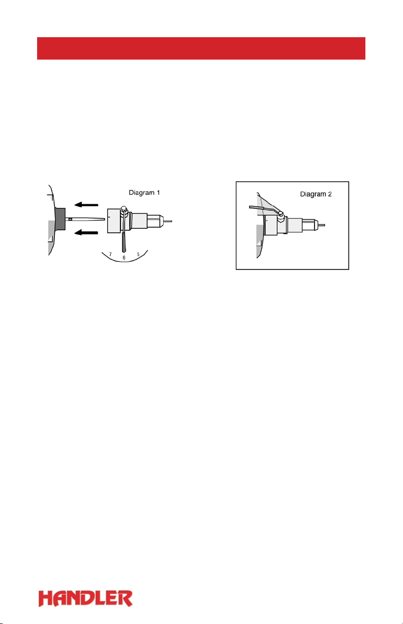
1. Remove the chuck remover
completely from the right side
(or for the left handed Chuk/
Changer) of the lathe
(See Fig. 1).
If you have a lathe manufactured
prior to 1972, remove the
set screw holding the chuck
remover located on the rear at
the lathes red hub. Remove the
chuck remover completely.
2. Remove the red polymer
cap from the motor hub. Sand
and/or scrap all paint from 2”
diameter lathe hub using the
emery cloth provided.
(See Fig. 3)
3. Using emery cloth, remove
burs, rust or paint from the
1/2” portion of the motor shaft.
4. Place clutch on to 1/2” portion of the
shaft, sliding clutch onto 1/2” portion to
shoulder inside 2” hub. The large diameter
of the aluminum portion of the clutch
should be positioned approximately 1/6”
from the 2” hub. (See Fig. 4)
5. Tighten set screw to mark the shaft
slightly. Loosen set screw and remove
clutch. File a small flat section where clutch
screw secures to 1/2” position of the shaft.
Lightly sand filed portion to remove the bur,
caused by filing. Replace clutch tightening
set screw securely.
Scrape off all red paint that is on
the 2” diameter housing.
1/2” shaft
File flat for
set screw
Remove -if hub has plastic
1/32” maximum allowable shaft
movement (end play) when
approximately 50 lbs pressure
is applied to end of shaft
Lathe
Hub
Pressure
applied here
If end play
exceeds 1/6”
condition must
be corrected.
6. With Chuk/Changer handle
in 6 o’clock position, place
Chuk/Changer with hub
adapter on to lathe hub.
A slight pressure may be
necessary to accomplish this
procedure. Tighten set screw
in Chuk/Changer’s hub adapter,
evenly
7. Slowly rotate chuck handle
clockwise, to 9:30 o’clock
position. Allow handle to
ease into position. Should the
handle stop beyond the 10:30
o’clock position, the chuck has
not been “slid” on to the hub
properly. (Place the handle
in the 6 o’clock position and
repeat Step 6 above, pushing
the entire assembly towards
the lathe.
8. Having adjusted the clutch handle into the
proper position, secure all set screws on the
adapter.
9. The operating range of the clutch handle is
6:00 o’clock counter-clockwise to OPEN the
collets and 9:30-10:30 o’clock to CLOSE collets.
MAKE CERTAIN never to close the collets
without a tool in it.
10. Clean collets every 30 days. Lubricating
outside of collets with a LIGHT coat of silicone
grease-ONLY. Always keep a tool in the collets
so the hardened collets will not take a smaller
diameter set.
NOTE: Should the clutch handle stop before the 9:30 o’clock
position, the adapter set screws should be loosened and the
entire chuck assembly pulled away from the the lathe. QUESTIONS? Review FAQ section on our website at:
www.handlermfg.com or call 1-908-233-7796.
Fig. 1 Fig. 2 Fig. 3
Fig. 4 Fig. 5 Fig. 6

16B Red Wing Lathe & Chuk/Changer Instruction 7
INSTALLATION & MAINTENANCE
CLUTCH SPRING ADJUSTMENT
Loosen the set screw on the spring housing. Hold the
handle in running position 9:15-10:30 o’clock. Rotate
spring housing counter-clockwise about 3/4 of a turn or
until set screw is facing approximately 11:00 o’clock
position. Tighten set screw securely. See insert diagram
for correct spring housing set screw position.
REPLACING CLUTCH SPRING
The clutch spring may be damaged if the handle is forced
beyond limits. See diagram at right. Chuk/Changer should
be installed on lathe while clutch spring is being replaced.
Remove Chuk/Changer handle by loosening handle set
screw. (Note: Mark side of cam shaft from which handle is
removed in order to facilitate proper replacement. Loosen
the set screw on the spirng housing. Remove spring
housing. Discard damaged spring. Insert new spring short
end first into small hole in spring housing. Replace spring
housing. Care should be taken to be sure long end of spring
enters small hole in chuck housing. Replace handle and
follow the adjustment procedure under Clutch Spring Adjustment.
REMOVE CHUCK FROM LATHE
Always move handle straight down (6:00 o’clock) and leave it in this position if you have
any reason to remove the chuck from the lathe. If handle is moved, the clutch spring
(Part No. 7) may be damaged or clutch spring tension may be released. When clutch
spring is damaged or tension released clutch will not engage properly. See instructions
under Clutch Spring Adjustment and replacing clutch spring. Normally it is not necessary
to remove the adapter or clutch from the lathe when you return the chuck to the factory
for repair. If it is necessary to remove adapter or clutch refer to the installation instruc-
tions for your particular model lathe. Serious damage to clutch or adapter will result if
instructions are not followed.
OVERHEATING
A new or rebuilt Chuk/Changer will normally run quite warm (very uncomfortable to the
touch) during the break in period. The break in period will usually last several weeks
depending upon speed and amount of use. Worn collects, collets not screwed in all the
way or too long a stop (Part No.3) will cause overheating, especially in the front portion
of the Chuk/Changer.
SQUEAKING CLUTCHES
After several months of service, a clutch may glaze and develop a squeak. The squeak is
usually most noticeable as the lathe is coasting to a stop. Remove chuck from lathe (see
instructions under removing chuck from lathe) and lightly sand both fiber and steel clutch
surfaces. If squeaking persists and there is a presence of excessive amounts of dust
around the clutch area, the adapter is improperly mounted, causing misalignment of the
clutches. Refer to installation instructions for your model lathe.

16B Red Wing Lathe & Chuk/Changer Instruction 8
OPERATION AND CARE INSTRUCTIONS
CAUTION
Do not attempt to operate Chuk/Changer unless it is properly installed on lathe.
Never oil or use solvents of any kind on Chuk/Changer
Never close collet without a tool (chuck,burr, etc) in the collet. Allow clutch spring to engage clutch.
(Never push up on handle or let handle snap up.)
Do not remove or attempt to defeat the purpose of the safety strap.
OPERATION
Normal running position, handle 9:15 o’clock to 10:30 o’clock.
To disengage clutch, bring handle down to 8:00 o’clock position, counter-clockwise.
To apply brake, bring handle down to approximately 7:00 o’clock position, counter-clockwise.
(Note: Brake position is used for changing arbor bands, buffing wheels, etc.) To open collet, bring
handle straight down to 6:00 o’clock position. Tools (chucks) burrs, etc., may be changed while
handle is in straight down (6:00 o’clock) position.
USE OF 3/32” DIAMETER SHANK TOOLS IN CHUK/CHANGER
1. With handle straight down, insert tool in inner collet to desired depth.
2. Move handle clockwise to approximately 8:00 o’clock position.
Remove hand from tool and allow clutch spring to return handle to running position.
3. Never push up on handle.
USE OF 1/4” DIAMETER SHANK TOOLS IN CHUK/CHANGER
1. With handle straight down, insert chuck shank into outer collet.
Note: The inner collet will be pushed back inside Chuk/Changer
2. While holding tool in collet, move handle clockwise to approximately 8:00 o’clock position.
3. Remove hand from tool and allow clutch spring to return handle to running position.
4. Never push up on handle.
CLEAN COLLETS EVERY 30 DAYS
1. With lathe switch OFF and clutch handle straight down, (collets open) unscrew otuer collet
(part No.5) with collet wrench (Part No.8) Unscrew counter-clockwise.
2. Remove both inner and outer collets
3. Thoroughly clean collet, you may use solvent to clean collets, however, you must remove all
traces of solvent before replacing.
4. Thoroughly clean collet body hole by using pipe cleaner or small cloth on end of instrument.
Do not use any solvents in this hole. Put a thin film of grease on outside of both collets. (This
purpose of this cleaning is to lubricate and prevent rust. Failure to clean and grease will cause
collets to slip and stick.)
5. Replace collets, with collet wrench, scrwing clockwise.
REPLACING WORN COLLETS
When tools (chucks) burrs, etc. begin to slip, collets should be replaced.* When replacing collets,
always use the shortest possible stop. Part No.3, that will still allow the tools to slip into the master
collet. WE recommend that you keep spare collets Part No.1 and
No. 5 and a set of stops, Part No.3S on hand at all times.
HOW TO REMOVE A STUCK COLLET
A collet may get rusty or dirty and stick if it is not cleaned and greased regularly, or it may stick if
collet is closed without a tool in the collet. Open collet by moving handle staright down (collet open).
Put collet wrench in collet and tap lightly on the end of the collet wrench and at the same time
attempt to unscrew the collet. If this does not loosen the collet, with the handle in the same position,
remove the four screws that hold the chuck on the adapter and remove chuck. Caution: be sure not
to move the handle during this procedure. See instructions under removing chuck from lathe. Grasp
the steel clutch plate to keep it from turning while you remove the collet.
*However, make certain collets have been properly cleaned. Dirty collets may also cause chuck slippage.

16B Red Wing Lathe & Chuk/Changer Instruction 9
CARE AND MAINTENANCE
PROTECTION - IMPORTANT
1. Never attempt to use a polishing motor without proper instruction.
2. Never use a polishing motor unless the motor has been fitted with polishing
splash hoods or a similar protective device containing a protective shield.
3. Always use a dust collector when performing polishing or grinding operations.
4. Read and follow all instructions contained in this manual regarding “tool safety.”
Handler manufactures a full line of Chucks, Splash Hoods, Dust Collectors, and
Protective Shields. Contact us at the number below to request a Handler Catalogue.
CHUCK REMOVAL
After finishing and completing a polishing or grinding operation, you may wish to remove
the chuck accessory and change to another type of chuck or accessory. This is completed
as follow:
1. Turn the lathe off and allow the shaft to come to a complete stop.
2. Using the chuck remover located on the left or right side of the lathe, pull upward on
the remover’s handle. This will push the remover outward, and push the chuck from
the lathe shaft, (See Figure 1. Page 4).
A few chucks may require the chuck remover to be rotated 360 Degrees before the
chuck accessory is removed. Chucks fitted to polishing motors containing a 1/2”
shaft are removed by loosening the set screw which holds it in position.
3. To place another chuck onto the lathe shaft, follow the procedure listed on this page.
CARE AND MAINTENANCE
Your Red Wing polishing motor has been fitted with ball bearings. No further lubrication is
necessary during the life of your motor. Occasionally remove the motor’s cord set from its
electrical source and wipe the unit clean with a clean, soft cloth. DO NOT use abrasive or
liquid cleaners. Read, fully, the safety instructions contained on page 6.
ACCESSORIES
Handler manufactures a full line of Chucks, Protective Hoods, Shields, and Dust Collectors
for use with your Red Wing motor. Handler chucks are precision manufactured to fit onto
your Red Wing motor. A few of these are described below.
The No. 7 L or R chuck is made to accommodate buffing
wheels and brushes for polishing acrylic dentures, plastics,
and metals. The threads contained on the tapered portion
of the chuck’s frontal surface secure the buff or brush in
position.
Handler’s 8T Jacobs type chucks are made to accommodate
from 3/32” to 1/4” burs and mandrels. It is manufactured
for gross finishing

16B Red Wing Lathe & Chuk/Changer Instruction 10
CHUCKS AND CHUCK CHANGERS
Handler’s No. 18 Atlas Jacobs type chuck
is precision ground to provide excellent
concentricity and durability. This chuck will
accommodate burs and mandrels from 0” to
1/4” in diameter. Available for right side ONLY.
Our No. 9 Arbor band chucks are built to
accept 3/4” x 3/4” abrasive bands. These are
used for gross finishing of plastics or metals -
Right or Left.
Handler’s No. 1-6 stone chucks are built to
accept abrasive stones and lathe wheels with
5/16”, 3/8” and 1/4”, arbor mountings for the
right and left side.
1 - 3/8” R 4 - 5/16” L
2 - 3/8”L 5 - 1/4” R
3 - 5/16” R 6 - 1/4” L
Note: Specify a No. 20 L or R chuck for a
polishing motor with a straight 1/2” shaft.
Handler has designed and built a full line of
automatic chucks which will adapt to your Red
Wing or other polishing motors. Handler’s
automatic chucks are durable and built to
save processing time and money.
16 CHUK/CHANGER
The Handler Chuk/Changer was designed to
provide full automatic, precision changing of
1/4” and 3/32” diameter burs, mandrels and
chuck accessories with the slight movement
of a handle while the motor is turning.
The Chuk/Changer provides the technician
with exacting concentricity and quick, easy
changing of various chucks which greatly
speeds grinding, polishing and finishing
procedures. The No. 16 Chuk/Changer is
adaptable to most types of dental motors,
including older models e.g. R&M, Ritter,
Baldor, Emesco and Red Wing.
NOTE: Specify make, model and catalogue number
of lathe when ordering 16L Chuk/Changer is for use
on left side of motor.
The No. 16 is shipped complete
with chuck accessories as follows:
(1) P-16-15 Arbor Band Chuck
(1) P-16-16 Spiral Tapered Chuck
(2) P-16-19 Stone Chucks
(2) P-16-20 Mandrels - for small
abrasive wheels.
(1) P-16-8 Collet Wrench
(1) P-16-10 Clutch
(1) P-16-ADW Adapter
No. 18 Atlas Jacobs
No. 9 Arbor band chucks
No. 1-6 stone chucks

16B Red Wing Lathe & Chuk/Changer Instruction 11
RED WING LATHE PARTS LIST
(1) PARTS LIST:
Locate part number on diagram. Specify, on order, identifying part number. Supply all data
on nameplate of your Red Wing Lathe - especially the serial number appearing on the last
line. (L = Left; R = Right)
PARTS:
No.1 Chuck Remover (Throw Off) -
Specify L or R
No.1a Chuck Remover Male Part -
Specify L or R
No.1b Chuck Remover Female Part -
Specify L or R
No.1c Handle for Throw-off
No.2 Chuck Remover -
set screw for male part
No.3 End Bell - one speed -
Specify L or R
No.4 Spacing Washers
No.5 Spring Washers
No.5a Bearing spacer - one speed -
Specify L or R
No.6 Thru-Bold with nuts
No.7 Bearings - two per set -
for right and left side - 1- and 2-
speed lathes.
No.8 Rotor -
specify whether 1 or 2 speed lathe
No.9 Centrifugal Switch -
specify whether 1 or 2 speed lathe
No.10 Field Ring - specify whether 1 or
2 speed lathe
No.11 Stator - specify whether 1 or 2
speed lathe
No.12 Hood Switch - specify whether 1 or
2 speed lathe
No.13 Insulating Washer - for hood
switch - one speed lathe
No.14 Supply Cord - including 2 prong
adaptor
No.14a 2 prong adaptor only
No.15 Switch - two speed (toggle)
No.15a Switch - one speed
No.16 Switch Washer
No.17 Base, Low - 4 1/2” shaft height
No.17a Base, high - 6” shaft height
No.18 Base Bolts and Washers -
low base (4-2 speed, 2-1 speed)
No.19 Base Plate
No.20 Rubber Base Grommets (set, 4)
No.21 Screws for above (set, 4)
No.22 Lubri-Plate - 1 3/4 oz tube

16B Red Wing Lathe & Chuk/Changer Instruction 12
Handler has designed and built a full line of automatic chucks which will adapt to your Red
Wing or other polishing motors. Handler’s automatic chucks are durable and built to save
processing time and money.
PROTECTIVE SHIELDS AND HOODS
Polishing and Grinding must be completed with the addition of a protective hood with shield
or a protective shield, Handler manufactures a full line of protective hoods and shields to
protect the technician from possible flying dusts and debris. Below are three examples of
the various types available.
The 86D hood shield provides adjustable protection for the technician. Constructed of
Ever-brite aluminum, it contains an adjustable 6”x9” clear acrylic shield to help protect the
polisher. Hoods are available in 6”x8” and 10” widths. Resin Hoods available in 6” width ONLY.
The protector was designed to provide protection from possible flying debris. Constructed
of 3/8” clear acrylic, the protector offers excellent protection for lathe and hand piece
grinding.
Protect yourself from UNIDENTIFIED FLYING OBJECTS. The New #26SHLD shield from
Handler mounts directly to your lathe. Made of 8” x 6” x 1/8” clear Polycarbonate, fully
adjustable, replaceable shield, helps comply with OSHA requirements. Comes with all
mounting hardware, Contact your dealer or Handler.
Handler manufactures a full line of protective hoods, shields, and dust collectors.
To obtain a Handler catalogue illustrating our hoods, shields, and dust collectors, visit our
website at: WWW.HANDLERMFG.COM or call 1-800-27HANDL (1-800-274-2635)
OSHA RECOMMENDED SHIELDS
79 86D 26SHLD

16B Red Wing Lathe & Chuk/Changer Instruction 13
PARTS AND ACCESSORIES
PARTS LIST:
Below is a list of parts and accessories for the RED WING and most other Bench Lathes.
No.1 Special collet for burrs and all 3/32” tools
No.1A A 3/32” burr adapter
No.1B A 1/8” burr adapter
No.1C A 3mm burr adapter
No.2 Pop-out spring
No.3 Stop (state length)
.265, .275, .285, .295, .305, .315
No.3S Set of 6 stops (one of each length)
(use shortest stop possible that will still
allow the tools to slip into the master collet)
(the life of a worn collet may be extended by
using a shorter stop)
No.4 Stop lock screw
No.5 Master collet - should be cleaned and lightly
greased every 60 days
No.6 Special collet, complete with pop-out spring
and .275 stop
No.7 Clutch spring (Note: If Chuk/Changer Wells
Type is used on left side, please state for left
side)
No.8 Collet wrench
No.9H Handle with plastic cushion grip
No.9HS Safety strap
No.10RW Clutch complete for all Red Wing lathes
No.10B Clutch complete for all Baldor lathes
No.10RM Clutch complete with bearing for all
Robbins-Myers lathes
No.10R Clutch complete with bearing
for all Ritter lathes
No.ADRW Adapter for all Red Wing Lathes
No.ADB300 Adapter for all Baldor lathes
No.ADB221 Adapter for all Baldor 221-240 series
lathes
No.ADB210 Adapter for all Baldor 210-211
series lathes
No.ADRM Adapter for all Robbins-Myers lathes
No.ADRC Adapter for all Ritter C lathes
No.ADRA Adapter for all Ritter A lathes
No.11 Clutch lining
No.12 Clutch lining screws (set of 3)
No.13 3/32” Hex wrench
No.14 Sandpaper chuck
No.15 Arbor band chuck 3/4” diameter
No.16 Sprial chuck
No.17 Field sandpaper chuck
No.18 Arbor for burrs
No.19 Stone chuck for tooth and knife stones, etc
No.20 Stainless steel mandrels with 1-64 screw
for heatless wheels etc
No.20S Screw only, 1-64 screw for No.20
No.21H Stainless steel mandrels with 2/64 screw
for 1-1/2” cutoff wheels
No.21HS Screw only, 2-64 for No. 21H
No.22 Bearings

16B Red Wing Lathe & Chuk/Changer Instruction 14
IMPORTANT NOTICE
WHAT SHOULD YOU DO TO RETURN GOODS
1. Our terms of sale are F.O.B. our plant. Handler makes every effort to insure the
proper delivery of goods, but we cannot guarantee the carrier’s performance. Each
product is tested and inspected for proper performance prior to leaving our facility.
The responsibility for damage in transit is the carrier’s, whether it is visible damage
or concealed damage.
2. Inspect this shipment IMMEDIATELY. Insist that visible damage or possible damage
be written on the Delivery Receipt by the receiver.
3. Inspect the contents of your shipment within 24 hours of receipt. Using your copy
of our packing list, check for piece count and accuracy immediately to insure proper
billing.
4. If damage is discovered, save all crates, cartons and packaging material until an
inspection has been made by an agent of the carrier.
5. In case of damage, notify the delivering carrier IMMEDIATELY requesting that an
inspection be made. Retain a copy of the inspection request for claim purposes.
Failure to notify the freight carrier immediately will result in the loss of your rights
to claim damage.
6. We have taken every precaution to insure safe arrival of your products. We cannot
be responsible for negligence by another party.
7. The receiver of the goods must make claims for incorrectly shipped goods to the
shipper within 15 days of receipt of delivery.
RETURNING GOODS
1. DO NOT return merchandise without our authorization. You must call first for a return
authorization number.
2. We will not accept returned merchandise from the carrier unless our authorization
NUMBER has been issued, and is clearly marked on the outside of the carton.
3. We will not accept goods (i.e. dust collectors) that are not cleaned and free of dust
and debris. The merchandise will be shipped back. This is in compliance with OSHA
regulations.
HANDLER MFG.
612 NORTH AVENUE EAST, WESTFIELD, NEW JERSEY 07090

16B Red Wing Lathe & Chuk/Changer Instruction 15
GROUNDING AND TOOL SAFETY
1. GROUNDING INSTRUCTIONS
This tool should be grounded while in use to protect the operator from electric shock.
The tool is equipped with an approved three-conductor cord and three-prong grounding
type plug to fit the proper grounding type receptacle. The green (or green and yellow)
conductor in the cord is the grounding wire. Never connect the green (or green and yellow)
wire to a live terminal. If your unit is for use on less than 150 volts, it has a plug that looks
like that shown in sketch (A) in Figure 1. If it is for use on 150 to 250 volts, it has a plug
that looks like that shown in sketch (B). Use of an extension cords or a 2 prong adapter is
not recommended.
2. TOOL SAFETY INSTRUCTIONS
1. Keep Work Area Clean: Cluttered
areas and benches invite accidents.
2. Avoid Dangerous Equipment
Don’t expose power tools to rain.
Don’t use power tools in damp or wet
locations. Keep work area well lit.
3. Keep Children Away
All visitors should be kept safe distance
from work area and appliance.
4. Store Idle Tools
When not in use, tools should be stored
in dry, high, and locked location out of
the reach of children.
5. Don’t Force Tool
It will do the job better and be safe at
the rate for which it was designed.
6. Use Right Tool
Don’t force small tool or attachment to
do the job of a heavy-duty tool.
7. Wear Proper Apparel
Do not wear loose clothing or jewelry which
may get caught in moving parts. Tie back
long hair or use a proper hair net.
8. Use Safety Glasses
Use safety glasses with all rotating tools.
Also use a face or dust mask if cutting
operation is dusty.
9. Don’t Abuse Cord
Never carry tool by cord or yank it to
disconnect from receptacle. Keep cord
from heat, oil, and sharp edges.
10. Secure Work
Use clamps or a vise to hold work. It’s
safer than using your hand and it frees
both hands to operate tool.
11. Don’t Overreach
Keep proper footing and balance at all
times.
12. Maintain Tools with Care
Keep tools sharp and clean for best and
safest performance. Follow instructions for
lubricating and changing accessories.
13. Disconnect Tools and TURN OFF.
When not in use; before servicing; when
changing accessories such as blades, bits,
cutters, etc.
14. Avoid Accidental Starting this and any other
appliance. Be sure switch is OFF when
plugging in.

WARRANTY
This HANDLER product is warranted to be free from defects in material and workmanship,
when used under the conditions recommended by the manufacturer, and/or the purpose for
which the product was intended, for a period of 12 months from the date of shipment from
factory to job site of original owner. Products purchased from distributor warehouse stock
are warranted for a period of 18 months from date of shipment from the manufacturer’s
warehouse.
In all cases, the full name and address of the distributor must be supplied, along with the
name of the customer, product name and number, and serial number. A copy of the original
invoice, showing date of purchase must accompany the warranty repair request.
This warranty will apply to equipment installed, operated and maintained in accordance
with HANDLER procedures and recommendations.
During the life of this warranty, HANDLER will repair or replace (At HANDLER’s option)
free of charge. F.O.B. its plant, any defective part or assembly, if such defect occurred in
normal service and was not due to apparent misuse, abuse, or accident.
Any warranty service performed in the field must be authorized by HANDLER MFG.
Unauthorized service voids the warranty and any resulting charge will not be paid by
HANDLER MFG.
HANDLER MFG. makes no other warranties or guarantees, expressed or implied.
The merchantability of the components is expressly excluded. The manufacturer assumes
no liability for indirect or consequential damages.
Detach or copy and mail back to the address below.
-------------------------------------------------------------------------------------------------------------------------
Customer Name:
Address:
City: State: Zip:
Model No.: Serial No.:
Distributor:
Distributor’s Address
Return to HANDLER
HANDLER MFG.
612 NORTH AVENUE EAST, PO BOX 520
WESTFIELD, NEW JERSEY 07090-0520
Table of contents
Other Handler Lathe manuals