Handling Systems 511 User manual

PHONE (888) 352-1213 • FAX (708) 352-6593 • McCook, IL
SERIAL #:
7KLVHTXLSPHQWVKRXOGQRWEHLQVWDOOHGRSHUDWHGRUPDLQWDLQHGE\DQ\SHUVRQ
ZKRKDVQRWUHDGDQGXQGHUVWRRGDOOWKHFRQWHQWVRIWKLVPDQXDO)DLOXUHWRUHDG
DQGFRPSO\ZLWKWKHFRQWHQWVRIWKLVPDQXDOFDQUHVXOWLQVHULRXVERGLO\LQMXU\RU
GHDWKDQGRUSURSHUW\GDPDJH
WARNING
MODEL 511/512/582
OWNER'S MANUAL
FIXED AND ADJUSTBALE HEIGHT GANTRY CRANE

Table of Contents
Section Page Number
Important Information and Warnings………………………………………………………...... 3
Technical Information and Specifications.......................................................... 4
Crane Terms……………………………………………………………………………........................ 5
Pre-Installation and Installation………………………………………………………................ 6
Swivel and Wheel Lock Assembly……………………………................………………........ 9
Tight Wire Kit (If Applicable)……………………………………………………………..………….. 10
Operation Introduction.................................................................................... 11
Shall’s and Shall Not’s for Operation…………………………………………………............ 12
Maintenance Inspection……………………………………………………………………….......... 13
Lubrication……………………………………………………………………………………………......... 14
Troubleshooting……………………………………………………………………………………......... 15
Warranty…………………………………………………………………………………….................... 16
Parts Information………………………………………………………………………….................. 17
Fixed Height Gantry Crane Parts Breakdown………………………………………............ 18
Adjustable Height Gantry Crane Parts Breakdown………………………………............ 19

ONLY COMPETENT ERECTION PERSONNEL FAMILIAR WITH STANDARD FABRICATION PRACTICES
SHOULD BE EMPLOYED TO ASSEMBLE HANDLING SYSTEMS CRANES BECAUSE OF NECESSITY IN
INTERPRETING THESE INSTRUCTIONS. HANDLING SYSTEMS IS NOT RESPONSIBLE FOR QUALITY
OF WORKMANSHIP PERFORMED DURING CRANE INSTALLATION.
WARNING
ALL HANDLING SYSTEMS EQUIPMENT IS NOT DESIGNED FOR OR MADE FOR TRANSPORTING HU-
MANS. FAILURE TO COMPLY WITH ANY ONE OF THE LIMITATIONS STATED IN THIS CRANE MAN-
UAL CAN RESULT IN PROPERTY DAMAGE, INJURY, OR DEATH. PLEASE TAKE ALL NECESSARY
PRECAUTIONS DURING INSTALLATION.
WARNING
CONSULT WITH A QUALIFIED STRUCTURAL ENGINEERED TO DETERMINE IF YOUR SUPPORT
STRUCTURE IS ADEQUATE TO SUPPORT THE LOADS GENERATED BY ANCHOR BOLT FORCE,
OVERTURNING MOMENT, OR AXIAL LOAD OF YOUR CRANE.
WARNING
CRANE CANNOT BE UTILIZED AS A GROUND: A SEPARATE GROUND WIRE IS REQUIRED.
WARNING
DO NOT MODIFY CRANE IN ANY WAY. ANY ALTERATIONS DONE IN THE FIELD WITHOUT CONSENT
FROM HANDLING SYSTEMS WILL VOID ALL WARRANTY.
WARNING
KEEP HANDS
CLEAR OF
ROTATING
PARTS!
DANGER
OVERLOADING AND IMPROPER USE CAN RESULT IN INJURY
WARNING
• MANUAL MUST BE FULLY READ AND
UNDERSTOOD BY QUALIFIED ERECTION
PERSONNEL PRIOR TO INSTALLATION AND USE
OF PRODUCT.
• CRANE IS NOT DESIGNED FOR AND SHOULD
NOT BE USED FOR LIFTING OR TRANSPORTING
HUMANS
• CRANE CAN NOT BE UTILIZED AS A GROUND.
• DO NOT FIELD MODIFY CRANE IN ANY WAY
• CONSULT WITH QUALIFIED STRUCTURAL ENGINEER
TO DETERMINE IF JIB CRANE SUPPORT STRUCTURE
IS ADEQUATE BASED ON THE LOADS GENERATED BY
THE JIB CRANE
WARNING
3
Important Information and Warnings

Technical Information and Specifications
Product Code
Operating Conditions and Environment
Temperature range: -30°F to +150°F (-34°C to 66°C)
Relative Humidity: 85% or less
4

Crane Terms
Anchor Bolts: Large steel bolts used to mount a base mounted pillar jib crane to the H.S.I. recommended foun-
dation.
Boom: The horizontal beam on which the hoist trolley travels.
Fitting Centers: The distance, centerline to centerline, between two support brackets (fittings) of a wall mounted
jib crane.
Capacity: The maximum live weight that the crane is designed to support.
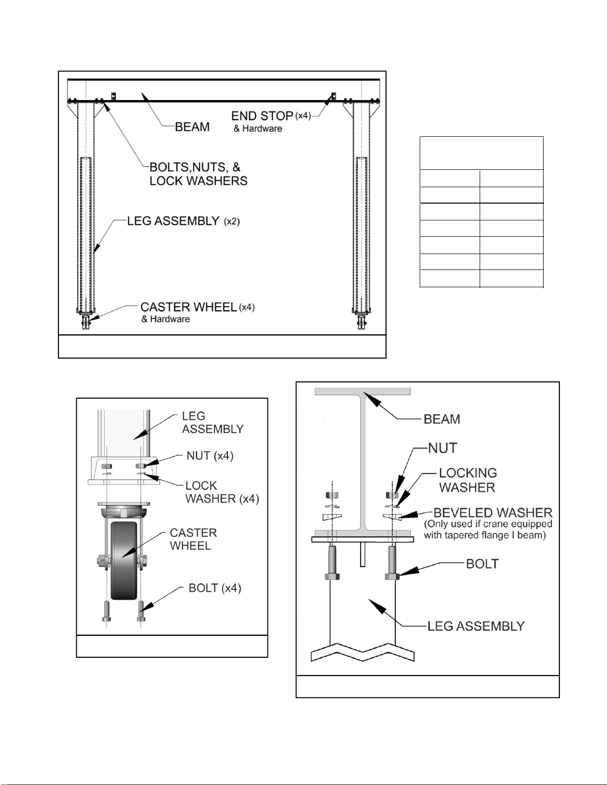
End Stops: Bolted to each end of the boom to prevent the trolley from falling off of the beam.
Foundation: For free standing pillar base mounted jibs. Foundations are used to support the jib and prevent it
from tipping over.
Gussets: Reinforcing plates used to stiffen mast at the base plate.
Head: Houses the roller, and lowers the crushing forces that are imposed on the mast.
Height Under the Boom (H.U.B.): The distance from the finished floor to the underside of the crane boom. To
find the under- boom, take the height of the load, plus the distance the load is lifted, plus the headroom require-
ments of the hoist/trolley and any attachments. Extra room aside from mandatory room needed could be helpful.
Mast: The vertical member of the jib, which supports the crane. Pillar jibs have round pipes as masts.
Overall Height: The highest point of the jib crane (including any hardware). A minimum clearance (usually 3”) is
required from any overhead obstruction.
Hoist: The actual lifting mechanism (powered by electric, air, or manual movement) that hangs from the trolley
that rides on the boom of a jib crane.
Trolley: The mechanism that travels back and forth on the crane boom (powered by electric, air, or manual
movement) which the hoist hangs from.
Overturning Moment: The overturning moment is the force applied to the mounting structure of a sefl-support-
ing pillar jib. This load is created by suspending a load from the boom, and is greatest at full load, at the very end
of the boom.
Rotation Stops: Limits the rotation of a pillar base mounted jib crane boom (which are standard at 360°). Stops
are field welded to the mast.
Span: The span for a pillar base mounted jib crane is the distance from the center of the mast to the end of the
boom. The span for a column mounted crane is measured from the face of the mounting surface to the end of the
boom. The span for a mast type jib crane is measured from the center of the vertical mast to the end of the
boom.
Thrust and Pull: Thrust and Pull are forces applied to a wall/column mounted jib cranes support structure. Thrust
is the pushing force exerted on the structure, and pull is the tensile, or pulling force. Thrust and Pull are equal to
each other (but opposite in direction), and are given for maximum at full load at the end of the boom.
Clear Span: The measurement between the end stops on a crane boom.
Hook Travel: The distance that the hook on the hoist travels.
In order to better understand jib cranes, here are the commonly used terms that are used to specify and design jibs.
5

6
Pre-Installation
1. Check crane for physical damage due to shipping.
2. Prior to assembly make sure all capacity stickers and warning labels are clearly visible and
properly affixed.
3. Check packing list to ensure no parts have been lost prior to initiating assembly of crane.
4. See Crane Drawing for bolt locations and dimensions.
5. Read entire manual before installing the crane.
6. WARNING Do not assemble/disassemble without proper lifting equipment.
7. Identify crane model (511 = fixed height, 512 = adjustable height). Reference Crane Drawing.
Find the applicable assembly instructions on Page 6 or Page 8 based on your crane model
type.
8. CAUTION Figures are for reference only and may differ for your particular application. Refer-
ence Crane Drawing included with crane information packet for specific information.
Installation
WARNING If multiple cranes were ordered, locate stamped serial number on each crane part for
proper part matching during installation. Although crane parts may appear to be identical, each crane
is assembled and built separately. All parts that do not have the same stamped serial number may
not line up properly for installation.
For Model 511 (Fixed Height Gantry):
1. Reference Figure 1 for general assembly layout.
2. Bolt two (2) CASTER WHEELS to each LEG ASSEMBLY using BOLTS, LOCK WASHERS,
AND NUTS provided and make sure that all fasteners are securely tightened (see Figure 2). If
applicable, attach optional swivel locks or wheel locks (see Page 9).
3. Secure span BEAM to the top of each LEG ASSEMBLY with the provided BOLTS, NUTS,
LOCK WASHERS, and (if applicable) BEVELED WASHERS (see Figure 3).
4. WARNING Do not operate or move crane without all fasteners and hardware in place and
properly secured. See Table 1 for torque specifications.
5. Install END STOPS onto BEAM using the hardware provided.
6. For units with Tight Wire Kit, refer to Page 10.

7
Figure 1 Model 511 (Fixed Height Gantry) Assembly
Figure 2 Caster to Leg Assembly
Figure 3 Model 511 Boom to Leg Assembly
BOLT DIA. TORQUE
1/4" - 20 6 ft.-lbs.
3/8" - 16 20 ft.-lbs.
1/2" - 13 50 ft.-lbs.
5/8" - 11 95 ft.-lbs.
3/4" - 10 175 ft.-lbs.
7/8" - 9 300 ft.-lbs.
Table 1
Torque Specifications

8
For Model 512 & 582 (Adjustable Height Gantry):
1. Reference Figure 4 general assembly layout.
2. Bolt two (2) CASTER WHEELS to each LEG ASSEMBLY using BOLTS, LOCK WASHERS,
AND NUTS provided and make sure that all fasteners are securely tightened (see Figure 2). If
applicable, attach optional swivel locks or wheel locks (see Page 9).
3. Secure BEAM for fastening to LEG ASSEMBLY. Loosen BOLTS on leg assembly TOP
PLATE. Slide BEAM under PLATES on both sides of LEG ASSEMBLY. Once complete, be
sure to tighten all bolts securely. Repeat step for attaching other LEG ASSEMBLY to other end
of BEAM (See Figure 5).
4. To obtain desired height, remove PINS (shipped in place at bottom-hole position) and lift to
desired height. Reinstall PIN and COTTER PIN securely.
5. WARNING Do not operate or move crane without all pins, fasteners and hardware in place
and properly secured. See Table 1 for torque specifications.
6. If applicable, install END STOPS onto BEAM (see Figure 1 for End Stops).
7. For units with Tight Wire Kit, refer to Page 10.
Figure 4 Model 512 (Adjustable Height Gantry) Assembly Figure 5 Model 512 Boom to Leg Assembly

9
Swivel Lock Assembly
1. Refer to Figure 6.
2. Attach the SWIVEL LOCK to each caster
wheel using the BOLTS, LOCK WASH-
ERS, and NUTS provided.
3. Pull on the PIN RING and rotate the
WHEEL to the desired PIN HOLE posi-
tion.
4. Release the PIN RING so that the LOCK-
ING PIN goes into the desired PIN
HOLE.
5. Ensure that the LOCKING PIN is in en-
gaged in the PIN HOLE.
Wheel Lock Assembly
1. Refer to Figure 7
2. Center SPANNER into WHEEL ASSEMBLY.
3. Place BRAKE SHOE over SPANNER and WASHER 1.
4. Position WHEEL between LEGS and insert BOLT through one side of CASTER to opposite
side.
5. Position WASHER 2 over protruding thread at the end of BOLT.
6. Position BRAKE LEVER over BOLT and against WASHER 2.
7. Position WASHER 3 and LOCK NUT over BOLT.
8. With BRAKE LEVEL in horizontal position, tighten LOCK NUT until wheel rotation is impeded.
9. Rotate LOCK NUT counter clockwise by ¼ turn increments until the WHEEL rotates freely with
the BRAKE LEVEL in a horizontal position.
10.Ensure proper operation. WHEEL must turn freely with BRAKE LEVER in “off” position
(horizontal). WHEEL must be locked with BRAKE LEVER in “on” position (rotated from hori-
zontal).
Figure 7 Wheel Lock Assembly
Figure 6 Swivel Lock Assembly

A
DETAIL A
SCALE 1 : 4
432 5
1
BOOM
END STOP
BRACKET
WELD
MAKE SURE TIGHT WIRE BRACKETS (WHICH ARE1.
WELDED TO END STOPS) ARE ON THE SAME SIDE OF
BOOM.
LOOP CABLE THROUGH EYE BOLT AT ONE END.2.
TIGHTEN WITH CABLE CLAMP. PUT "S" HOOKS ON
CABLE. LOOP CABLE THROUGH OTHER EYE BOLT.
TIGHTEN WITH CABLE CLAMP.
SLIP EYE BOLT THROUGH TIGHT WIRE BRACKET AND3.
TIGHTEN EYE BOLT UNTIL TIGHT WIRE IS TIGHT.
**NOTE: 361 MODEL JIB ONLY REAR TIGHT WIRE4.
BRACKET IS BOLTED TO REAR GUSSET ON BOOM.
**NOTE: FOR CRANES WITH 6" BEAM TIGHT WIRE5.
BRACKET MAY HAVE DIFFERENT ORIENTATION DUE
TO SPACE CONSTRAINTS.
ITEM
NO. DESCRIPTION QTY.
1 TIGHT WIRE ANGLES (WELDED TO ES) 2
2 1/8" DIA CABLE (LENGTH = CRANE SPAN) 1
3 CABLE CLAMPS 2
4 5/16" EYE BOLTS W/ NUTS 2
5 "S" HOOKS #
DATE
DRAWN
D. Grujic
1:10
DRAWING
SIZE
DRAWN
BY
DESCRIPTION
HANDLING SYSTEMS INTERNATIONAL
LAGRANGE, IL 60525
PROPRIETARY AND CONFIDENTIAL:
THE INFORMATION CONTAINED IN THIS DRAWING IS THE SOLE PROPERTY OF HANDLING SYSTEMS INTERNATIONAL,
INC. ANY REPRODUCTION IN PART OR AS A WHOLE WITHOUT THE WRITTEN PERMISSION OF HANDLING SYSTEMS INTERNATIONAL, INC. IS PROHIBITED.
TOLERANCES:
DECIMALS (UNLESS OTHERWISE SPECIFIED) TWO PLACE (.00) + / .015 THREE (.000) +/ .005
ANGLES +/ 30 MINUTES ALL DIMENSIONS ARE IN INCHES UNLESS OTHERWISE SPECIFIED.
SCALE:
TIGHT WIRE ASSEMBLY
SHEET
NUMBER
05/02/07 A 1
MATERIAL
PART NUMBER 9990000
9990000
10

Operation Introduction
The suggestions below are not intended to take precedence over existing plant safety rules and regu-
lations or OSHA regulations. It is the responsibility of the owner to make personnel aware of all feder-
al, state and local rules and codes, and to make certain operators are properly trained.
DANGER
DO NOT WALK UNDER A SUSPENDED LOAD
KEEP HANDS CLEAR OF ROTATING PARTS
WARNING
CRANE OPERATORS SHALL BE REQUIRED TO READ THE OPERATION SECTION OF THIS
MANUAL, THE WARNINGS CONTAINED IN THIS MANUAL, INSTRUCTION AND WARNING
LABELS ON THE HOIST OR LIFTING SYSTEM, APPLICABLE ANSI AND OSHA SAFETY
STANDARDS, AND THE CRANE OPERATOR’S MANUAL PUBLISHED BY THE CRANE
MANUFACTURER’S ASSOCIATION OF AMERICA (CMAA). THE OPERATOR SHALL ALSO BE
REQUIRED TO BE FAMILIAR WITH THE CRANE AND CRANE CONTROLS BEFORE BEING
AUTHORIZED TO OPERATE THE CRANE OR LIFTING SYSTEM.
CRANE OPERATORS SHOULD BE TRAINED IN PROPER RIGGING PROCEDURES FOR THE
ATTACHMENT OF LOADS TO THE HOIST HOOK.
CRANE OPERATORS SHOULD BE TRAINED TO BE AWARE OF POTENTIAL MALFUNC-
TIONS OF THE EQUIPMENT THAT REQUIRE ADJUSTMENT OR REPAIR, AND TO BE IN-
STRUCTED TO STOP OPERATION IF SUCH MALFUNCTIONS OCCUR, AND TO
IMMEDIATELY ADVISE THEIR SUPERVISOR SO CORRECTIVE ACTION CAN BE TAKEN.
CRANE OPERATORS SHOULD HAVE NORMAL DEPTH PERCEPTION, FIELD OF VISION, RE-
ACTION TIME, MANUAL DEXTERITY, HEARING, AND COORDINATION.
CRANE OPERATORS SHOULD NOT HAVE A HISTORY OF OR BE PRONE TO SEIZURES,
LOSS OF PHYSICAL CONTROL, PHYSICAL DEFECTS, OR EMOTIONAL INSTABILITY THAT
COULD RESULT IN ACTIONS OF THE OPERATOR BEING A HAZARD TO THE OPERATOR
OR TO OTHERS.
CRANE OPERATORS SHOULD NOT OPERATE A CRANE OR LIFTING SYSTEM WHEN UN-
DER THE INFLUENCE OF ALCOHOL, DRUGS, OR MEDICATION.
NOTICE
Read OSHA Specification 1910.179 “Overhead and Gantry Cranes,” ANSI
B30.11, “Monorails and Underhung Cranes,” ASMEB30.16, and any other
applicable standards.
Read the hoist manufacturer’s Operating and Maintenance Instructions.
Read all labels attached to equipment.
11

Improper operation of a crane can create a potentially hazardous situation which, if
not avoided, could result in death or serious injury, and substantial property dam-
age. To avoid such a potentially hazardous situation THE OPERATOR SHALL:
NOT operate a damaged, malfunctioning
or unusually performing crane.
NOT operate a crane until you have thor-
oughly read and understood
Manufacturer’s Operating and Mainte-
nance Instructions or Manuals.
Be familiar with operating controls, proce-
dures, and warnings.
NOT operate a crane that has been modi-
fied without the manufacturer’s approval.
NOT lift more than rated load for the
crane/hoist/trolley.
NOT use the crane to lift, support, or
transport people.
NOT lift loads over people.
NOT operate a crane unless all persons
are and remain clear of the supported
load.
NOT operate unless load is centered un-
der hoist.
NOT leave load supported by the
crane/hoist unattended unless specific
precautions have been taken.
NOT allow the crane to be used as an
electrical or welding ground.
NOT remove or obscure the warnings on
the crane.
NOT operate a crane on which the safety
placards or decals are missing or illegible.
NOT operate a crane that has any
changes in rolling effort or unusual nois-
es.
Warn personnel before lifting or moving a
load.
Warn personnel of an approaching load.
Ensure that end-stops are in place.
Ensure that all bolts are tight and have
lockwashers.
NOT put hands near rotating parts.
WARNING
Improper operation of a crane can create a potentially hazardous situation which, if
not avoided, could result in minor or moderate injury, or property damage. To avoid
such a potentially hazardous situation THE OPERATOR SHALL:
Maintain a firm footing or be otherwise
secured when operating the crane.
Make sure the load is free to move and
will clear all obstructions.
Avoid swinging the load or hook.
Inspect the crane regularly, replace dam-
aged or worn parts, and keep appropriate
records of maintenance.
Use the crane manufacturer’s recom-
mended parts when repairing the unit.
Lubricate the roller bearings per crane
manufacturer’s recommendations.
NOT allow your attention to be diverted
from operating the crane.
NOT allow the crane to be subjected to
sharp contact with other cranes, struc-
tures, or objects through misuse.
NOT adjust or repair the crane unless
qualified to perform such adjustments or
repairs.
Ensure that festooning cannot be
snagged or pinched.
JIB BOOM OPERATION
Verify the hook is high enough to clear
any obstruction before using the boom of
the jib crane.
Ensure the jib boom is directly over the
load before lifting the load.
Start moving the jib boom slowly and
bring it up to speed gradually.
Reduce the speed of the boom as it ap-
proaches the place where it should stop.
TROLLEY OPERATION
Refer to the trolley’s operating instruc-
tions.
HOIST OPERATION
Refer to the hoist’s operating instructions.
Shall’s and Shall Not’s for Operation
WARNING
12

Any changes in rolling effort or unusual noises must be immediately identified and corrected.
WARNING
13
Maintenance Inspection
Figure
No. Item Inspection Frequency
1Top Plate
Hardware
Check that the lock-washers are fully compressed and the nuts are
tightened to manufacturer’s specifications (Table 1).
Before and After
Each Use
2 Caster Hardware Check that the lock-washers are fully compressed and the nuts are
tightened to manufacturer’s specifications (Table 1).
Before and After
Each Use
3Locating Pins and
Cotter Pins Make sure locating pins and cotter pins are securely in place. Before and After
Each Use
4 Casters
Keep casters lubricated through zirk fittings.
Check for cracks, grooves, pitting, or excessive wear. Wheels
should be replaced if these conditions exist.
Every 1000
hours Or 6
months
5End Stop/Tight
Wire Kit
Check that the lock-washers are fully compressed and the nuts are
tightened the proper torque specifications (Table 1).
Every 500 hours
Or 3 months
- Additional Items Conduct a general inspection of all additional items you may have
purchased.
Every 1000
hours Or 6
months
- General
Conduct a visual inspection of the crane overall and speak with the
crane operator about the crane’s performance, if any flaws are
noticed take crane out of service and report to manufacturer
immediately.
Every 1000
hours Or 6
months
Table 2 Crane Inspection

Lubrication
1. The most economical way to maintain a jib/gantry crane and keep it in good operating condi-
tion is to lubricate all moving parts regularly.
2. Regular inspection of all parts should be made and all loose parts should be adjusted. Parts
that become worn should be replaced at once.
3. The interval of lubrication varies as to the use of the machine. A crane operating 24 hours a
day, 7 days a week, should demand lubrication once a week. Whereas a standard duty crane,
operating eight hours a day on a five day week should be lubricated once every two to three
weeks. Cranes under a standby classification, being used once or twice a month, should be
lubricated at least once every six months.
4. The actual interval from one lubrication to the next depends entirely upon the type and length
of operation to which the crane is subjected. These factors are variable and sometimes cannot
be definitely determined. In this case, the crane operator or maintenance engineer would de-
termine when the crane should be lubricated.
5. The casters on the gantry crane require lubrication. Grease fittings are provided.
6. Grease for casters should comply with NLGI No. 1 or No. 2.
7. If Texaco products are not available, equivalent lubricants are satisfactory.
14

Troubleshooting
15
Symptom Cause Remedy
Casters are worn or damaged Replace casters
Casters need grease Grease casters
There is an obstruction at wheel(s) Remove obstruction
Table 3 Troubleshooting Guide
Crane does not move
smoothly

11 Year Warranty
HSI’s 11 year warranty is the best in the industry.
The Fine Print:
Handling Systems International, Inc. (known as H.S.I.) warrants manual push/pull Jib and
Gantry Crane products it manufactures against defects in material or workmanship for a period
of eleven years from date of receipt by purchaser or customer. This warranty does not cover
failure or defect in paint or material finish. This warranty does not cover failure or defect
caused by operation in excess of recommended rated capacities, misuses, negligence or
accident, and alteration or repair of any kind not authorized by H.S.I. H.S.I. systems shall
not be modified after manufacture without written authorization of H.S.I. Any field
modifications made without written authorization of H.S.I. shall void all H.S.I.’s warranty
obligation. H.S.I. agrees to furnish the same or substantially similar replacement part (new
or repaired) free of charge, providing the buyer gives immediate written notice of alleged
defects, and if requested by H.S.I., returns the defective parts to the factory, for H.S.I.’s
inspection and examination. Purchaser or end user shall be solely responsible for all freight
and transportation costs incurred in connection with any warranty work provided by H.S.I.
hereunder. H.S.I. will not be liable for any loss, injury or damage to persons or property,
nor for damages of any kind resulting from failure or defective operation of any materials or
equipment furnished hereunder. H.S.I. shall not be liable under any circumstances for any
incidental, special and/or consequential damages whatsoever, whether or not foreseeable,
including but not limited to damages for lost profits and all such incidental, special and/or
consequential damages are hereby also specifically disclaimed. This warranty applies only to
H.S.I. equipment or materials which, after our inspection, are determined to be defective
either in material supplied or workmanship performed by H.S.I. Where equipment is furnished
by H.S.I. but not of its manufacture, H.S.I.’s liability is limited to such adjustment as the
actual manufacturer makes to H.S.I. H.S.I. will not be liable for the cost of repairs,
alterations, or replacements or any expense connected therewith made or incurred by the
purchaser or his agents or employees, except upon written authority from H.S.I. This warranty
is personal to purchaser only and applies only to equipment which purchaser has properly
operated and maintained in accordance with H.S.I.’s written instructions. H.S.I. assumes no
liability for any consequential damages suffered through the use of loss of use of its
equipment. This constitutes H.S.I.’s sole warranty with respect to the equipment and material
manufactured by itself. H.S.I. makes no other warranty of any kind whatsoever, expressed or
implied, and all implied warranties of merchantability and fitness for a particular purpose
which exceed the aforementioned obligation are hereby disclaimed by H.S.I.
What Products Are Covered?
•Manual Rotation Jib Cranes
• Manual Steel Gantry Cranes
• Defects in material and workmanship
16

17
Parts Information
When ordering Parts, please provide the crane serial number which is stamped into each crane part (see
Figure 9). The serial number is also located underneath the “HSI” logo.
Figure 8 Serial Number Locations

Model 511 Fixed Height Gantry Crane Parts Breakdown
18
Figure 9 Model 511 Fixed Height Gantry Crane
Figure No. Description Qty
1 Caster 4
2 Bolt 16
3 Locking Washer 16
4 Nut 16
5 Leg Assembly 2
6 Beam 1
7 Bolt -
8 Locking Washer -
9 Nut -
10 End Stop 4
11 Bolt 8
12 Locking Washer 8
13 Nut 8

19
Model 512 Adjustable Height Gantry Crane Parts Breakdown
Figure 10 Model 512 Adjustable Height Gantry Crane
Figure
No. Description Qty
1 Caster 4
2 Bolt 16
3 Locking Washer 16
4 Nut 16
5 Leg Assembly 2
6 Beam 1
7 Bolt -
8 Plate -
9 Square Beveled Washer -
10 Locking Washer -
11 Nut -
12 Pin 2
13 Cotter Pin 2

20
Model 582 Adjustable Height Aluminum Gantry Crane Parts Breakdown
Figure 11 Model 582 (Adjustable Height Aluminum Gantry)
1
2
34
5
6
78
910
11
12
13
This manual suits for next models
2
Table of contents
Popular Construction Equipment manuals by other brands

TUBESCA-COMABI
TUBESCA-COMABI TOTEM 2 CROSS 2 Assembly manual

Altrad Belle
Altrad Belle EASY SCREED PRO Operator's manual

SealMaster
SealMaster 300 owner's manual

felton industries
felton industries FEL4PPS Assembly instructions

Fayat Group
Fayat Group BOMAG BW177D-50 Operating instructions, maintenance instructions

Terex
Terex RT700 Operator's manual