Hands Free Farm RANGER User manual

User Guide

PN 875-0416-01 Rev A

HANDSFREEFARM.COM
1
GETTING STARTED
Read and understand all safety warnings
Make sure you fully understand all the safety warnings before installing and
using RANGER. See page 2.
Check package contents
Refer to the Kit Contents page in this guide to confirm you have received all
parts of your RANGER install kit. See page 3.
Install RANGER
Use the instructions in this guide to install RANGER. See page 4.
Power on and Use RANGER
Turn on RANGER and learn discover how to use RANGER to provide GPS
guidance to efficiently working your field. See page 7.
Get help when needed
Visit handsfreefarm.com to learn more about RANGER or to download the full
RANGER documentation suite.
Have a question or issue? Submit your question anytime on
handsfreefarm.com or call Customer Service at 1-866-888-4472 (U.S. or
Canada) during business hours.
1
2
3
4
5

SAFETY WARNINGS
HANDSFREEFARM.COM
2
Safety Warnings
The warnings below provide information that identifies hazards associated with potential injury or death and tells
you how to avoid them. The warnings apply whenever you use RANGER. Read and understand this manual and
all the warnings below before installing, operating, or performing maintenance or service on RANGER. Do not
allow anyone to operate without instruction. For questions or further assistance, contact Customer Service. Keep
this manual and all related safety information with the manuals for your tractor and other implements.
Warnings
Role of Operator - As with other navigation guidance systems within vehicles, pay attention to driving
the vehicle. To avoid serious injury or death, do not become distracted by other tasks and always be
prepared to respond to field conditions. Stay seated while the vehicle is moving.
Manual Override - Stop following the path displayed by RANGER if it is unsafe to proceed, such as
when an obstacle is in the line of travel or there is an emergency. RANGER cannot identify obstacles
or hazards in the field; only you can do this.
Tractor Overturns - Accounting for the largest number of agricultural vehicle-related fatalities each
year on farms, overturns are more likely to occur on slopes. RANGER cannot identify environments
that pose an increased risk of overturn; only you can do this.
Collisions with People and Objects - The second leading cause of agricultural vehicle-related
fatalities occurs when vehicles run over people. RANGER cannot identify bystanders or other objects,
such as trees, fences, boulders, and other equipment. Stop following the path indicated by RANGER
to avoid people and objects.
Operator Position - You must manually control the direction and speed of the tractor. Always remain
in the operator position in the tractor when using RANGER.
Installing RANGER - Before installing RANGER inspect the vehicle and perform any needed
maintenance, such as a loose steering wheel, wheels out of alignment, uneven tire pressure, and
contaminated hydraulic fluid. RANGER may not perform as intended on a vehicle that is not properly
maintained. Errors in vehicle performance while following RANGER guidance increase the risk of
operator and bystander injury or death.
Turn off the vehicle and disengage RANGER when installing or performing maintenance. Before
attempting to install any RANGER components, park the vehicle on a clean level floor with adequate
clearance to work all around. Use an appropriate ladder or platform when installing or performing
maintenance on cables, the antenna, and other RANGER components.
Before you perform any drilling, cutting or fastening, ensure that no other vehicle components, such as
electrical wiring, will be damaged. Failure to follow this warning may cause physical injury and/or
damage to the machine. To avoid burns or electric shock injury when installing or removing RANGER,
do not touch parts of the vehicle that are heated or electrically energized.
Mounting the Console - Mount the RANGER console where it can be seen clearly and is within
reach. Do not place in a location where it interferes with seeing other information, controls, or the field.
Looking at the screen for too long while operating the vehicle can cause a crash.
Attaching the Battery - Avoid contact with cables that carry high current. Connect RANGER power
cables to a stable 12 V power supply.
Operating RANGER - To avoid serious injury or death be prepared to respond to field conditions. Do
not become distracted by other tasks. Always pay attention to the task of driving the vehicle and stay
seated while the vehicle is in motion.
!
!
!
!
!
!
!
!
!

HANDSFREEFARM.COM
3
KIT CONTENTS
Kit Contents
Unpack your RANGER kit and identify the parts as shown.
Part Number Qty Description Photograph
803-0066-000 1 Console
150-1013-000# 1 Antenna, 1575.42 MHz
604-0019-000# 1 Console mounting (suction cup) hardware
675-1123-000# 4 Screw, machine, 8-32, 7/16"
Attach mounting ball to back of console
051-0167-000# 1 Main power (power/ground speed) cable
054-0100-000# 1 Power (cigarette lighter) adapter cable
601-0003-005#
683-0001-008#
1
1
Disk, zinc, 3-3/8" diameter, 3/16" thick
Foam pad, circular, 3" diameter, 0.045" thick
(antenna mounting hardware)
INSTALLING RANGER
HANDSFREEFARM.COM
4
Installing RANGER
Note: Proper installation is critical for safe and optimal RANGER operation.
The following sections represent typical installation order; however, install components in your preferred order.
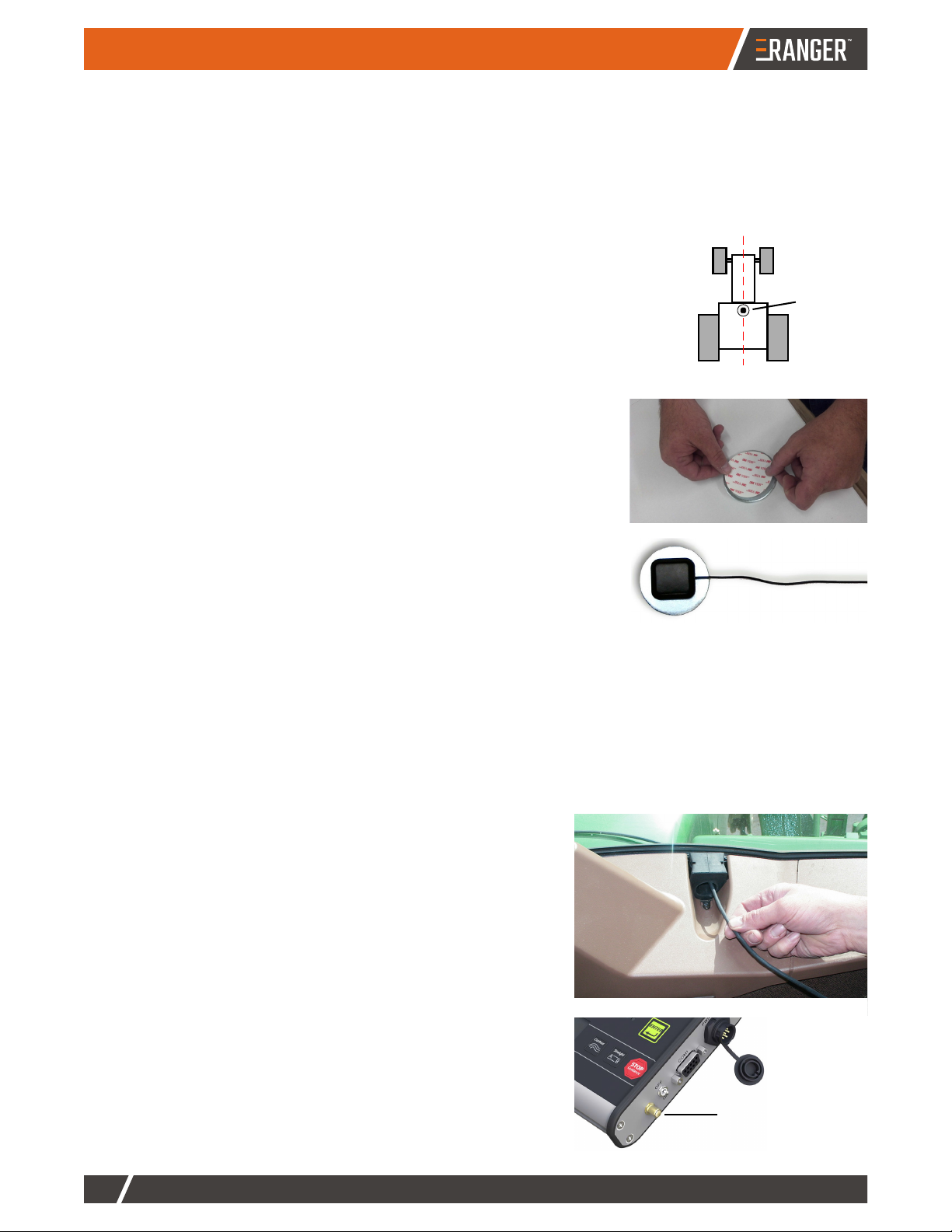
Mounting the Antenna
Mount the antenna in a location that will optimize its performance—typically along the
left/right centerline of the vehicle as high and as far forward as possible (usually along
the leading edge of the vehicle cab). Do not place the antenna within two feet of a
transmitting radio antenna (such as a two-way or business band radio).
To mount the antenna:
1. Clean and dry the vehicle surface where you will attach the antenna
mounting plate.
2. Remove the paper backing from one side of the adhesive disk then
affix the disk to the bottom of the antenna mounting plate.
3. Remove the other paper backing from the adhesive disk (see at
right).
4. Position the mounting plate in your preferred location then press
down hard for proper adhesion.
5. Place the magnetic mounted antenna on the plate, making sure the
antenna is on the left/right centerline of the vehicle (see at right).
Routing the Antenna Cable
When routing the antenna cable:
• Make sure the RANGER console is powered off before attaching the cables.
• DO NOT bend the cable to a radius of less than 6”.
• DO NOT route the cable within 12” of radio wires, power generator wires, a heat source, or moving parts.
• Coil excess cable in a protected location and secure the installation with tie straps.
To route the antenna cable:
1. Route the cable through a cab opening where rubber
protection exists that will protect the cable (see top right).
2. Attach the other end of the antenna cable to the console (see
bottom right).
Antenna
Attach antenna
cable here

HANDSFREEFARM.COM
5
INSTALLING RANGER
Connecting the Console to a Power Source
Connect the console to your preferred power source using one of the two options below.
Option 1
Connect to 12 V Power Source
Option 2
Connect to Compatible Rate Controller
1. Connect one end of the main power cable
to the console.
2. Connect the other end to the power
adapter cable.
3. Plug the cigarette lighter plug of the power
adapter cable into the cigarette lighter port
or available 12 V power port in your cab.
4. Coil excess cable in a protected location
then secure the installation with tie straps.
1. Connect one end of the main power cable
to the console.
2. Connect the other end of the main power
cable to a compatible rate controller speed
sensor port.
Note: The main power cable is compatible
with rate controllers that require a Dickey
John speed sensor connection. An
optional cable is available from Outback
Guidance to allow connection to rate
controllers that require a Raven speed
sensor connection.
3. Coil excess cable in a protected location
then secure the installation with tie straps.
Main power
cable
Power adapter
cable
Rate controller
back
Rate controller
front
INSTALLING RANGER
HANDSFREEFARM.COM
6
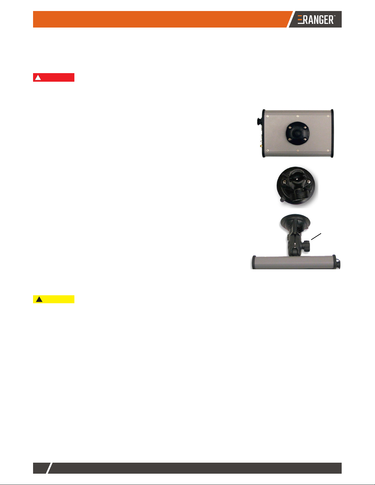
Mounting the Console
Before mounting the console, determine an appropriate mounting location. Typically, you mount the console above
and behind the center of the steering wheel just below your line of sight. The simplest installation is on the front
glass of the cab, but you can vacuum mount the console to any non-porous (metal) surface.
To mount the console:
1. Using the four machine screws, attach the RAM ball mount securely
to the back of the RANGER console.
2. Using the two self-tapping screws, install the RAM pedestal to the
vacuum cup. Tighten the screws securely.
3. Attach the RAM pedestal to the RAM ball on the back of the
RANGER console.
4. Thoroughly clean the inside cab window surface directly in front of
the steering wheel.
5. Press the vacuum mount to the window and twist the actuator until it
clicks over center to create adhesion to the glass.
6. Loosen the RAM mount and adjust the console to the proper
viewing angle.
Do not mount the console in a location where it interferes with seeing other information, controls,
or the field. Looking at the screen for too long while operating the vehicle can cause a crash.
Do not leave the console unattended for extended periods of time. If possible, remove the
console from the glass when it is not in use. Continued exposure to the elements (such as direct
sunlight) may damage the suction cup. To extend the life of the suction cup clean it periodically
per manufacturer’s instructions.
WARNING:
!
Twist
actuator
CAUTION
!
HANDSFREEFARM.COM
7
USING RANGER
Using Ranger
The following sections get you up and running quickly to use RANGER to optimize your guided-steering work.
• “Powering RANGER and Verifying Your GPS Signal” (below)
• “Console Overview” on page 8
• “Guidance Mode Feature Comparison” on page 9
• “Setting Up RANGER” on page 10
• “Using Straight Guidance” on page 13
• “Using Contour Guidance” on page 15
• “Displaying Field and Driving Information While Receiving Guidance” on page 16
• “Performing Additional Tasks with RANGER” on page 17
• “Support” on page 18
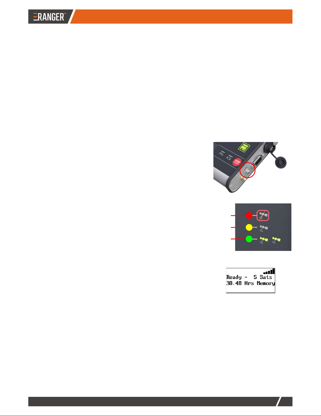
Powering RANGER and Verifying Your GPS Signal
The RANGER power switch is on right side of the console (circled at right).
• Flip the switch to ON to power up RANGER
• Flip the switch to OFF to power down RANGER
Upon power up and with your antenna having a clear view of the sky,
RANGER automatically begins acquiring a GPS signal (see indicators at
right). When RANGER has acquired a GPS signal the yellow (GPS) LED
illuminates. When RANGER acquires a more accurate
differentially-corrected (DGPS) signal, the green LED illuminates. This
startup process may take several minutes.
The green DGPS LED must be illuminated for RANGER to provide
guidance.
With startup complete, the RANGER display appears similar to that at right
with the following information:
• Vertical bars in upper right indicate GPS signal strength, where more
black bars means greater signal strength
• ‘Ready’ status - RANGER is ready to provide guidance
• Number of satellites being tracked (‘5 Sats’ at right)
• Memory (storage space) available to log (store) field data
No signal
GPS
DGPS
USING RANGER
HANDSFREEFARM.COM
8
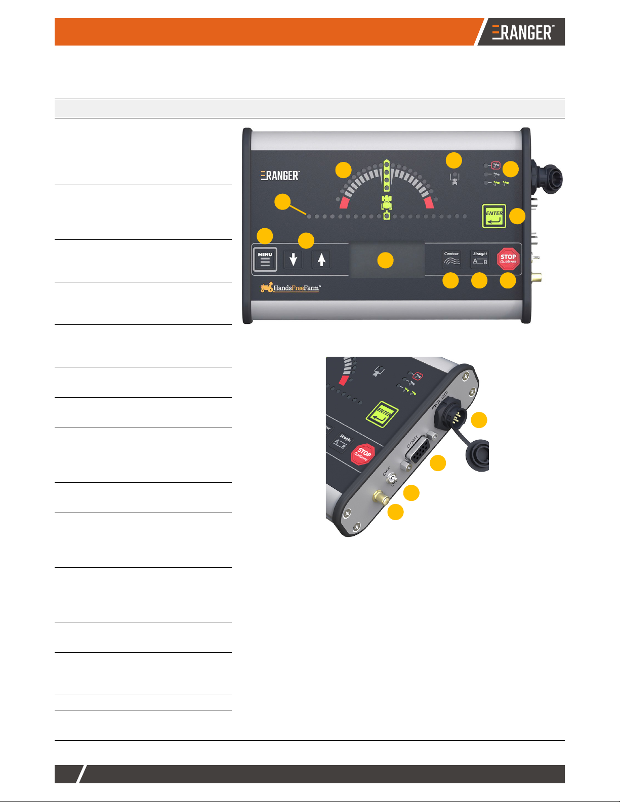
Console Overview
The following table shows the front and rear views of the RANGER terminal and describes each numbered feature.
Item Description Views
1 Steering guide (LEDs arc)
Illuminated LEDs left/right of
center indicate direction you
need to steer to become
centered on pass
2 Crosstrack (LEDs row)
Illuminated LEDs left/right of
center indicate pass is certain
distance left/right of vehicle
3 MENU button
Display the menu and
navigate the submenus
4 Down/up arrows
Navigate menus or cycle
through guidance screens
5 Display
Shows menus or guidance
information
6 Contour button
Start Contour guidance mode
7 Straight button
Start Straight guidance mode
8 STOP Guidance button
Stop guidance/logging and
display menu of additional
functionality
9ENTER button
Confirm menu selections
10 GPS indicators/LEDs
Top (red) = no GPS
Middle (yellow) = GPS
Bottom (green) = DGPS
11 Headland indicator/LED
Illuminates when the vehicle
crosses into a previously
applied area
12 Power port
Connect main power cable
13 COM1 (serial) port
Connect to external devices or
transfer data
14 Power (ON/OFF) switch
15 Antenna port
Connect antenna cable
5
6 7 8
9
10
1
4
3
12
13
14
15
11
2
HANDSFREEFARM.COM
9
USING RANGER
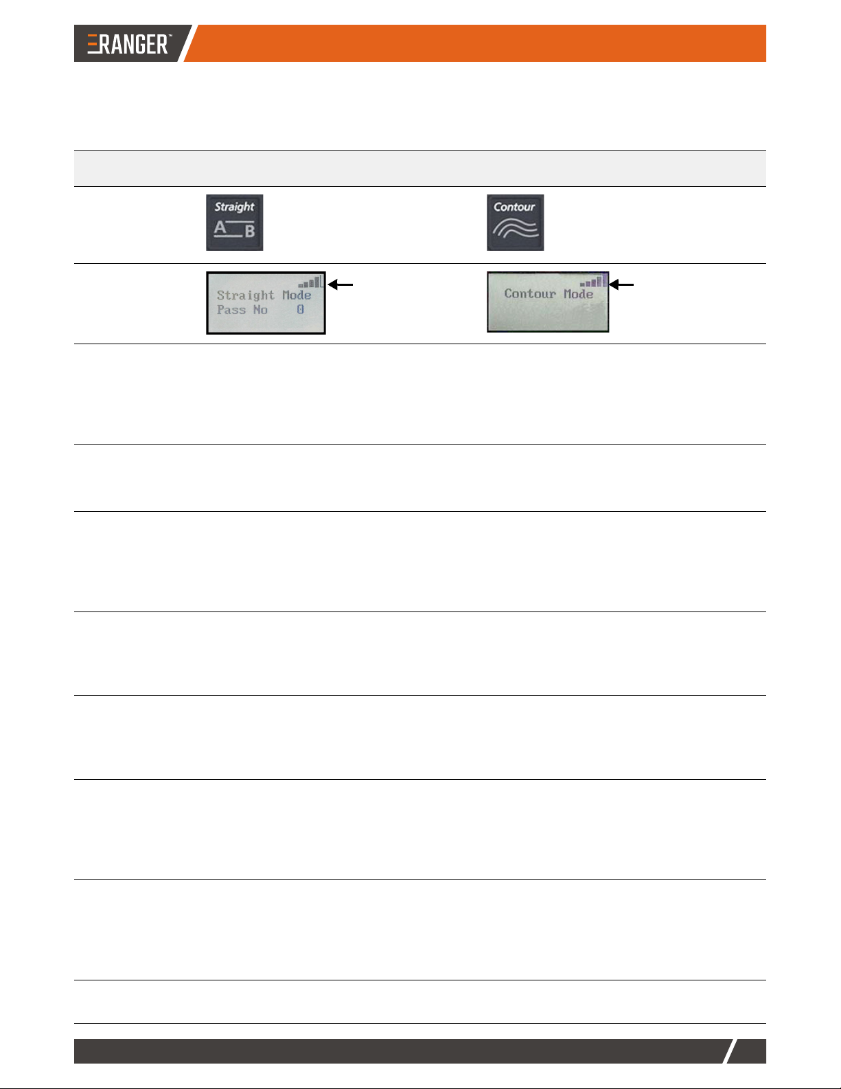
Guidance Mode Feature Comparison
RANGER supports two guidance options: Straight guidance mode and Contour guidance mode. Use the table
below to learn about each mode.
Feature Straight Mode Contour Mode
Guidance mode
button and type
Predefined parallel and
numbered passes, where
passes can be straight or
circular.
Freestyle, where RANGER
guides relative to any previous
pass.
Main guidance
display
Work recorded
(logged) in
memory?
Yes
Although recorded work in Straight mode is
not used for guidance, it is used if you
switch to Contour mode and then want to
make a pass along previous work.
Yes
The recorded pass defines guidance for the
next pass.
A and B points
required?
Yes
A/B points define the first pass; subsequent
passes are laid out automatically.
No
Guidance is based on previous passes.
Guide from
previous pass?
No
Straight guidance only looks at predefined
parallel lines spaced by the implement
width, as entered in the Swath Width menu.
Yes
If RANGER recognizes a previous pass
close by, it automatically begins guiding on
that pass. Wherever the previous pass goes
guides the next pass.
Numbered
passes?
Yes
The first A=B line is pass 0 (zero). Passes
to the right increment +1, +2, etc. and
passes to the left decrement -1, -2, etc.
No
Swath width
integrity across
the field?
Yes
All passes are equally spaced in multiples
of the swath width (ideal for planting,
harvesting, ditching, and furrowing).
No
Guidance works from the last pass, so
driving errors add as you work across the
field. Each pass redefines the next pass.
Switch modes? Yes
Switch from Straight to Contour mode at
any time by pressing the Contour button.
Contour mode recognizes previous passes
driven in Straight mode.
Yes
Switch from Contour to Straight mode by
pressing the Straight button. You then have
the option of using a previous A=B line or
setting a new A=B line.
Skip passes? Yes
You can complete passes in any order and
they will still be equally spaced across the
field.
Yes, however...
If you skip an area, RANGER recognizes it
as a new pass and continues logging.
RANGER can guide using the new pass or
continue guiding using previous passes.
Calculate field
area?
No Yes
GPS signal quality
(3-4 bars typical
with SBAS)
GPS signal quality
(3-4 bars typical
with SBAS)
USING RANGER
HANDSFREEFARM.COM
10
Setting Up RANGER
RANGER includes several settings that enable you to tailor your system to your needs. Review the following
sections to quickly set up RANGER for your field.
• “Settings Overview” (below) - shows all the settings in a single map and describes the buttons you use to
access the menu, navigate the menu, and change/view settings
• “Setup Menu” on page 11 - describes items on the Setup menu
• “Service Menu” on page 12 - describes items on the Service menu
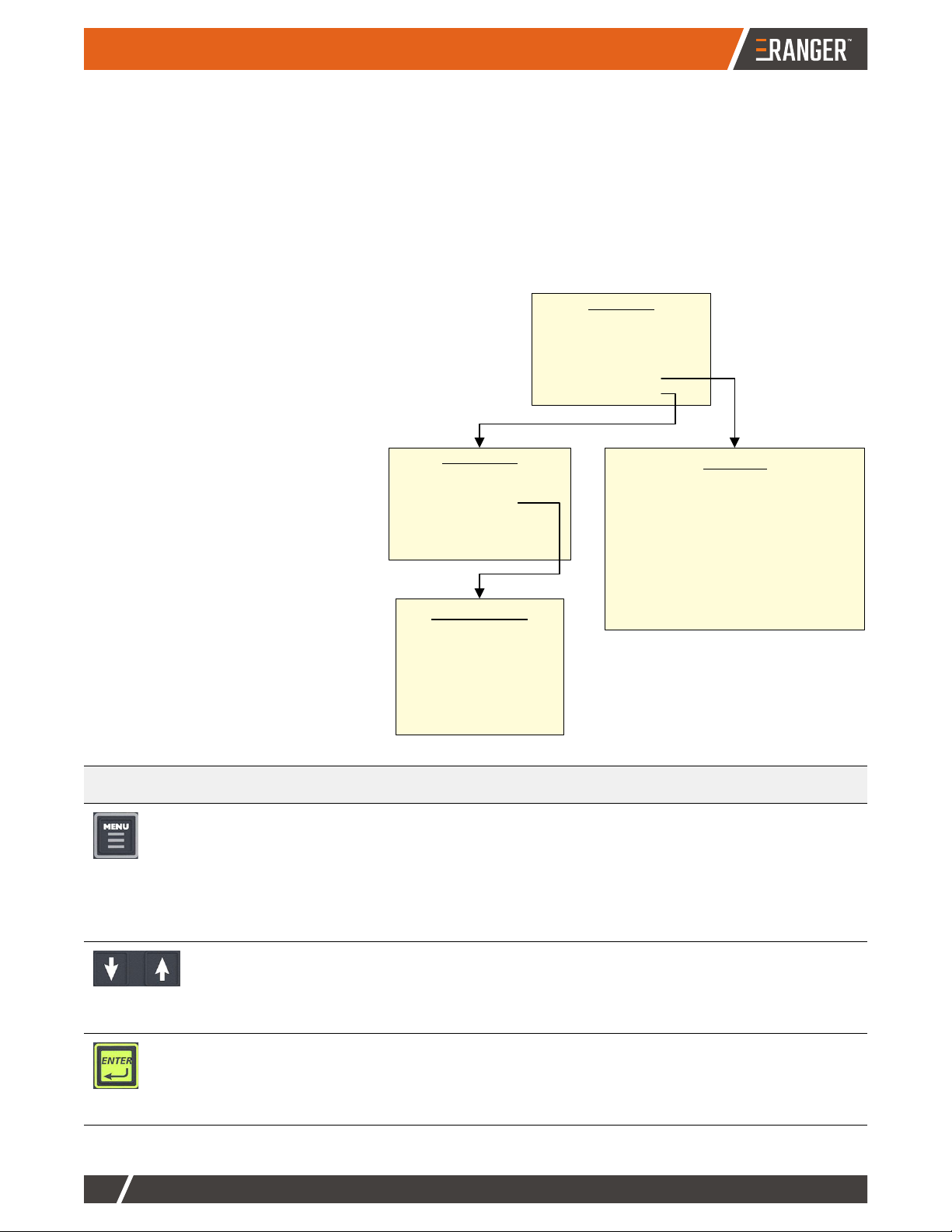
Settings Overview
The map at right shows all available
RANGER settings. The map enables you
to quickly identify what settings are
available and where they are in the menu
system.
Use the map in conjunction with the button
descriptions below to quickly change any
applicable settings.
Button Purpose
• Press MENU to initially display the Setup menu (top menu in figure above).
• When on the Setup menu, press MENU to exit the menu system.
• When on the Diagnostics or Service menu, press MENU to return to the Setup menu.
• When editing Swath Width, press MENU to move one numerical place to the left (see Swath
Width below). For example, if the tens place is the current editable value, press MENU to
move to the hundreds place.
• Use the arrows to move down or up the list of menu items. The selected menu item is
preceded by ‘>’.
• When editing Swath Width, press the arrows to decrease (down arrow) or increase (up arrow)
the current number place (such as hundreds or tenths).
• Press ENTER make a setting editable, then, after using the arrows to select a value, press
ENTER to confirm the selection.
• When editing Swath Width, press ENTER to move one numerical place to the right. When the
rightmost place is editable, press ENTER to confirm the value and return to the Setup menu.
Setup Menu
Brightness 5
Swath Width 30.00
Sensitivity Medium
Perimeter Setup Right
Diagnostics >
Service Menu >
Diagnostics
Correction Type SBAS
Sats Trk=10, Use in Calc=09
STDEV 0.04 ft
HDOP 1.20
Diff Age 0001 secs
Bit Rate Error 0-0
GPS Software Ver. 6.8
App Software Ver. 1.0
Serial Number 300556
Memory 29.87 hr./98% Free
Service Menu
Correction Type SBAS
SBAS Satellite AUTO
NMEA Port Setup >
Unit of Measure Feet
Language English
Reset Defaults >
NMEA Port Setup
NMEA Port Baud 4800
GGA 1 Hz
GLL Off
VTG 1 Hz
RMC Off
GSA Off
ZDA Off
*
*The Diagnostics menu is
read-only (you cannot change
any Diagnostics values).

HANDSFREEFARM.COM
11
USING RANGER
Setup Menu
To display the Setup menu, press
To set Brightness, Sensitivity, Perimeter Setup:
1. Press MENU, then press the up/down arrows to select an item (the selected item is preceded by ‘>’).
2. Press ENTER to make the item editable.
3. Press the up/down arrows to change the value, then press ENTER to confirm the change.
4. Press MENU to exit the menu.
To set Swath Width:
1. Press MENU, then press the up/down arrows to select Swath width (preceded by ‘>’).
2. Press ENTER to display the swath width value with hundreds selected (underlined editable value).
3. Press the up/down arrows to change the selected value.
4. Press ENTER or MENU to select the next place to the right or left, respectively.
5. Press the up/down arrows to change the selected value.
6. Repeat steps 5 and 6 to change any other places.
7. Press ENTER until the hundredths place is selected, press ENTER again to return to the menu, then press
MENU to close the menu.
Menu Item Default Description
Brightness Range: 1 (low) to 10
(high)
Default: 5
Display brightness. The LEDs indicate the level as you change it.
Swath Width Default: 30.00 ft Width of the implement or boom.
Sensitivity Options: Low, Medium,
or High
Default: Medium
Guidance sensitivity level that determines how aggressively the
RANGER steering guide LEDs guide you toward your pass when
approaching it from close proximity.
• Low: Smooth guidance adjustments, eventual lack of
crosstrack accuracy (in this sense, crosstrack is the real-
time, constantly changing perpendicular offset of the vehicle
to the desired position on your pass).
• Medium: Good compromise between smooth guidance and
crosstrack accuracy; typical setting for most vehicles.
• High: Aggressive guidance adjustments with highest
crosstrack accuracy.
Perimeter
Setup
Options: Left, Center, or
Right
Default: Right
Edge of your swath width used in field area calculation. See
“Calculating the Area of a Field” on page 15.
Diagnostics See “Diagnostics Menu” on page 18.
Service Menu See “Service Menu” on the next page.
Setup Menu
Brightness 5
Swath Width 30.00
Sensitivity Medium
Perimeter Setup Right
Diagnostics >
Service Menu >

USING RANGER
HANDSFREEFARM.COM
12
Service Menu
To display the Service menu, press
Note: RANGER supports third-party applications designed to receive DGPS signals from an external receiver over
an RS-232 serial interface using NMEA 0183 messages. Various third-party connecting cables and kits are
available for such applications as yield monitors, rate controllers, and laptops. Make sure RANGER and the
external application use the same baud rate. When using an output rate of 5 HZ use a higher baud rate (such as
19200) than the default (4800).
Menu Item Default Description
Correction
Type
Options: SBAS, e-Dif
Default: SBAS
Differential correction type used by RANGER to
improve GPS positioning accuracy.
• SBAS (default) is available throughout most
of North America and does not require any
configuration.
• e-Dif is most relevant outside North America
and is intended only for relative guidance
applications and is not recommended for
data recording and subsequent comparative
analysis.
It is recommended that North America customers
use the default (SBAS).
SBAS Satellite Options: AUTO, W122, W134, W135,
W138, E120, E124, E126, E131,
M129, M137
Default: AUTO
Menu item appears only when correction type is
SBAS. If not using AUTO (default), for North
America SBAS coverage use a WAAS satellite
(W122, W134, W135, or W138).
NMEA Port
Setup
(see Note
below table)
Options (defaults in bold):
NMEA Port Baud: 19200, 9600, 4800
GGA: OFF,.2 HZ, 1 HZ, 5 HZ
GLL: OFF,.2 HZ, 1 HZ, 5 HZ
VTG: OFF,.2 HZ, 1 HZ, 5 HZ
RMC: OFF,.2 HZ, 1 HZ, 5 HZ
GSA: OFF,.2 HZ, 1 HZ, 5 HZ
ZDA: OFF,.2 HZ, 1 HZ, 5 HZ
Baud rate and GPS message output rates used by
RANGER when
• NMEA Port Baud:
• Messages (GGA through ZDA): Set the
frequency of message data. For example,
set GGA to 5 Hz to transmit GGA message
data five times per second (once every 0.2
seconds).
Unit of
Measure
Options: Feet, Meters
Default: Feet
Unit of measure used throughout the display.
Language Options: Multiple languages
supported.
Default: English
Language used throughout the display. Language
options vary depending on the language group
installed RANGER. Contact Outback Guidance
Customer Service for questions regarding
language groups.
Reset Defaults N/A Reset factory defaults.
Service Menu
Correction Type SBAS
SBAS Satellite AUTO
NMEA Port Setup >
Unit of Measure Feet
Language English
Reset Defaults >
until Service
is selected
HANDSFREEFARM.COM
13
USING RANGER
To set Correction Type, SBAS Satellite, Unite of Measure, or Language:
1. From the Service menu, press the down arrow until the item you want to edit is selected. When you first
displays the Service menu, Correction Type is selected.
2. Press ENTER to make the item editable.
3. Press the up/down arrows to change the value, then press ENTER to confirm the change.
4. Press MENU twice to exit the menu (return to ‘Ready’ screen).
To set NMEA Port Setup options:
1. From the Service menu, press down arrow until NMEA Port Setup is selected.
2. Press ENTER. NMEA Port Baud is selected.
3. Press ENTER to make the item editable, press the up/down arrows to change the value, the press ENTER
to confirm the selection and return to the Service menu with the same item (NMEA Port Setup) selected.
4. Repeat steps 1 through 3 for each message (starting with GGA) that you want to change the message
output rate.
5. Press MENU three times to exit the menu (return to ‘Ready’ screen).
To reset default settings:
1. From the Service menu, press down arrow until Reset Defaults is selected.
2. Press ENTER twice. * Please Wait * appears briefly then Reset Defaults is selected.
3. Press MENU twice to exit the menu (return to ‘Ready’ screen).
Using Straight Guidance
Drive the first pass along a straight side of the field or down the middle of the field to divide the field with a straight
swath working out to each side.
Tip! Before driving A=B lines to work your field, you typically drive a perimeter along the edges of the field. You
must use Contour guidance mode to drive the perimeter. This calculates the field area at the same time. See
“Calculating the Area of a Field” on page 15.
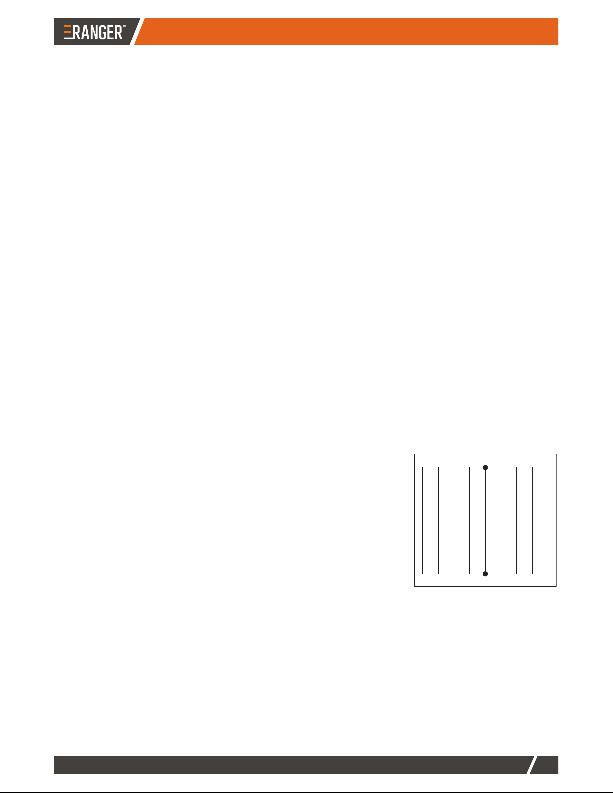
Driving an A=B Line
An A=B line is an imaginary line that passes through two points to define the
first pass. All other passes are uniformly spaced on both sides of the first pass.
Once an A=B line is established, RANGER generates an invisible array of
equally spaced swath lines in multiples of the swath width parallel to and
emanating from both sides of the A=B line (see figure at right) and provides
guidance along any line you steer the tractor to.
While turning around at the headland, the nearest pass number is displayed.
You can work passes in any order.
Note: Remember to press STOP Guidance when you no longer want
RANGER to guide (no longer log data).
A
B
432101234
USING RANGER
HANDSFREEFARM.COM
14
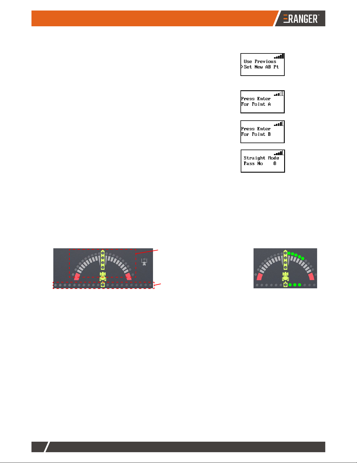
To drive an A=B line:
1. Position the vehicle at the beginning of the first pass.
2. Press Straight. Set New AB Pt is selected (preceded by ‘>’).
Note: If this is the first time using RANGER or if you have erased
memory, only ‘Set New AB Pt’ appears and is selected. Otherwise,
‘Use Previous’ appears above ‘Set New AB Pt’ and is selected. Press
the down arrow to select ‘Set New AB Pt’.
3. With Set New AB Pt selected, press ENTER.
4. Press the ENTER button to mark Point A.
5. Drive the first pass, then at the end of the pass press ENTER to mark
Point B. Upon marking Point B, RANGER automatically begins
guiding and the screen indicates you are on pass 0 (zero).
6. Turn around and drive toward the next pass. RANGER auto-detects the pass and begins guiding.
The steering guide indicates if you are centered on your pass (vertical yellow LEDs) or if you need to steer
left or right to become centered on your pass (red LEDs on left = steer to left; green LEDs on right = steer
to right).
The crosstrack bar indicates the pass is a certain distance left (red LEDs on left) or right (green LEDs on
right) of your vehicle. As you steer toward your pass, fewer crosstrack LEDs are illuminated and when you
are centered on your pass the center crosstrack LED is illuminated.
7. When you have finished your field press STOP Guidance to stop guiding (stop logging data). You are
done, so you can press MENU to return to the ‘Ready’ screen.
Steering guide
(illuminated LEDs indicate direction
you need to steer to become
centered on pass)
Crosstrack
(illuminated LEDs show pass is certain
distance left or right of your vehicle)
Example - need to steer right
HANDSFREEFARM.COM
15
USING RANGER
Snapping the A=B Line to Your Current Position
While in Straight guidance mode, you can move (or ‘snap’) the A=B line to your current position (parallel to the
original A=B line) on-the-go without interrupting guidance operation. This is typically used to correct for DGPS drift
over time or to insert a desired gap between consecutive parallel swaths (such as a conservation barrier strip).
1. While in Straight guidance mode, press up arrow once to display the snap screen.
2. Press Straight to align the nearest A=B line with the current vehicle position (AB LINE
SNAPPED appears), then press down arrow to return to the Straight guidance screen.
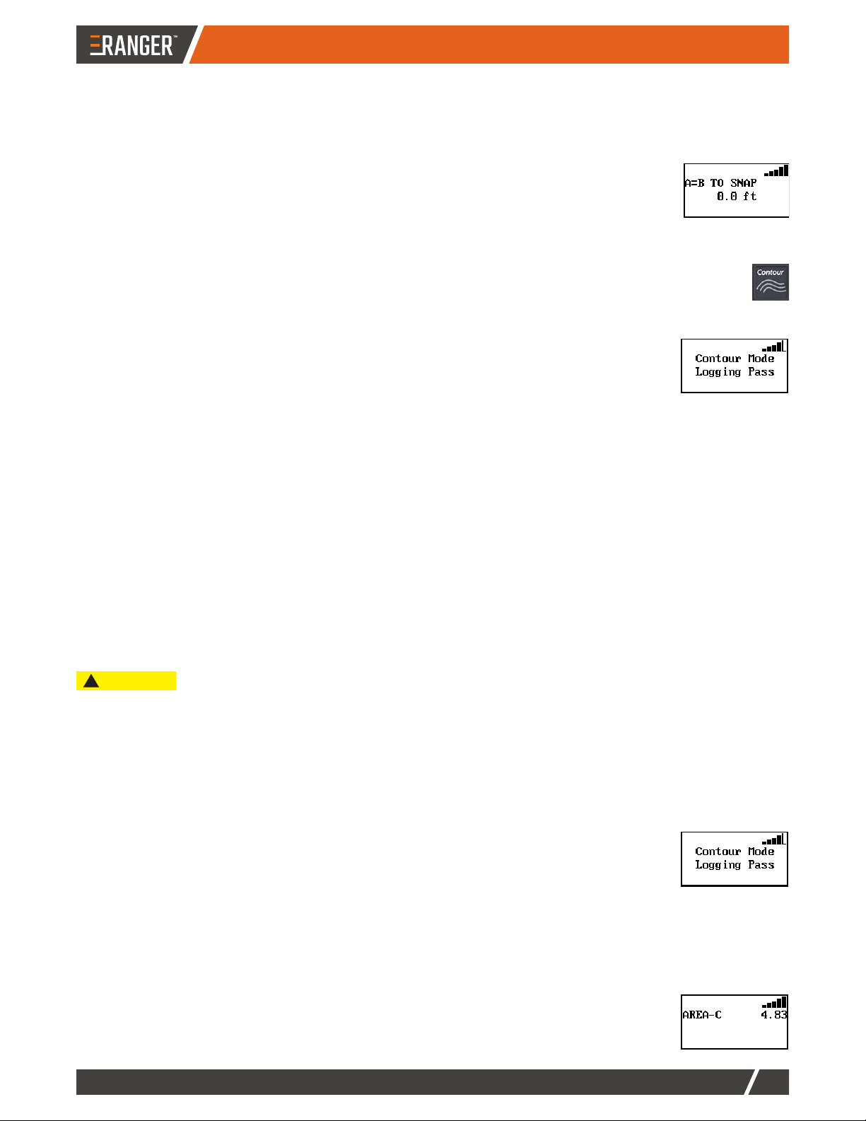
Using Contour Guidance
You typically use Contour guidance when driving perimeters, turning around, and following contoured
(uneven) fields. You can drive an initial pass or guide from a previous pass. When driving your initial pass,
you do not need the steering guide lights as there is no previous pass to follow. When following a previous
pass, RANGER provides guidance.
1. Press Contour before beginning the initial pass. The display shows “Logging Pass”.
2. Make the initial pass without using the steering guide.
3. At the end of the current pass, turn around and begin the next pass. RANGER
automatically detects the previous pass and begins guiding on a new pass.
Guiding on Subsequent Passes
Anytime the vehicle is within half a swath width of a previously logged pass, RANGER automatically begins to
guide. In Contour mode, RANGER can guide from any previous pass, even those made in Straight guidance mode.
Making A New First Pass (Starting a New Contour Pass)
While working a field in Contour mode, you may need to drive a pass that follows a different path than the previous
passes. Simply drive the new path. Once RANGER recognizes the new pass, it starts logging data for this pass
(displays ‘Logging Pass’ for the pass). Subsequent passes are guided from this newly defined pass.
Calculating the Area of a Field
At the beginning of each new field, you can use RANGER to calculate the field perimeter area of the first contour
pass around the field. If you set units to feet, the area is in acres; if units are meters, the area is in hectares.
To calculate the area of a field:
1. Erase any existing field data: Press STOP Guidance, press down arrow until Erase Memory is selected,
then press ENTER. ‘Erasing Swaths’ may appear briefly on the screen before RANGER exits the menu.
2. Set the swath position used to calculate the perimeter: Press MENU, press either arrow (up or down) until
Perimeter Setup is selected, then press ENTER. Press either arrow (up or down) until your preferred
perimeter position (Left, Right, or Center) is selected, then press ENTER.
3. Drive the perimeter in Contour mode: Press Contour, then drive the vehicle around the
outside edge of the field. During this time RANGER logs data (calculating the field
area) and the screen displays ‘Contour Mode Logging Pass’. RANGER continuously
updates the area calculation until the vehicle is within one swath width of the starting
point. RANGER then automatically closes the perimeter and displays the final field area
calculation.
Note: You can press down arrow while driving your perimeter to view a constantly
updated area calculation on the screen. Otherwise, wait until RANGER closes the
perimeter (see next step).
4. Press down arrow to display the perimeter area calculations. The displayed AREA-’x’
shows the current perimeter setup selection where ‘x’ is L=left, C=center, or R=right.
The following procedure involves erasing memory.
CAUTION
!
USING RANGER
HANDSFREEFARM.COM
16
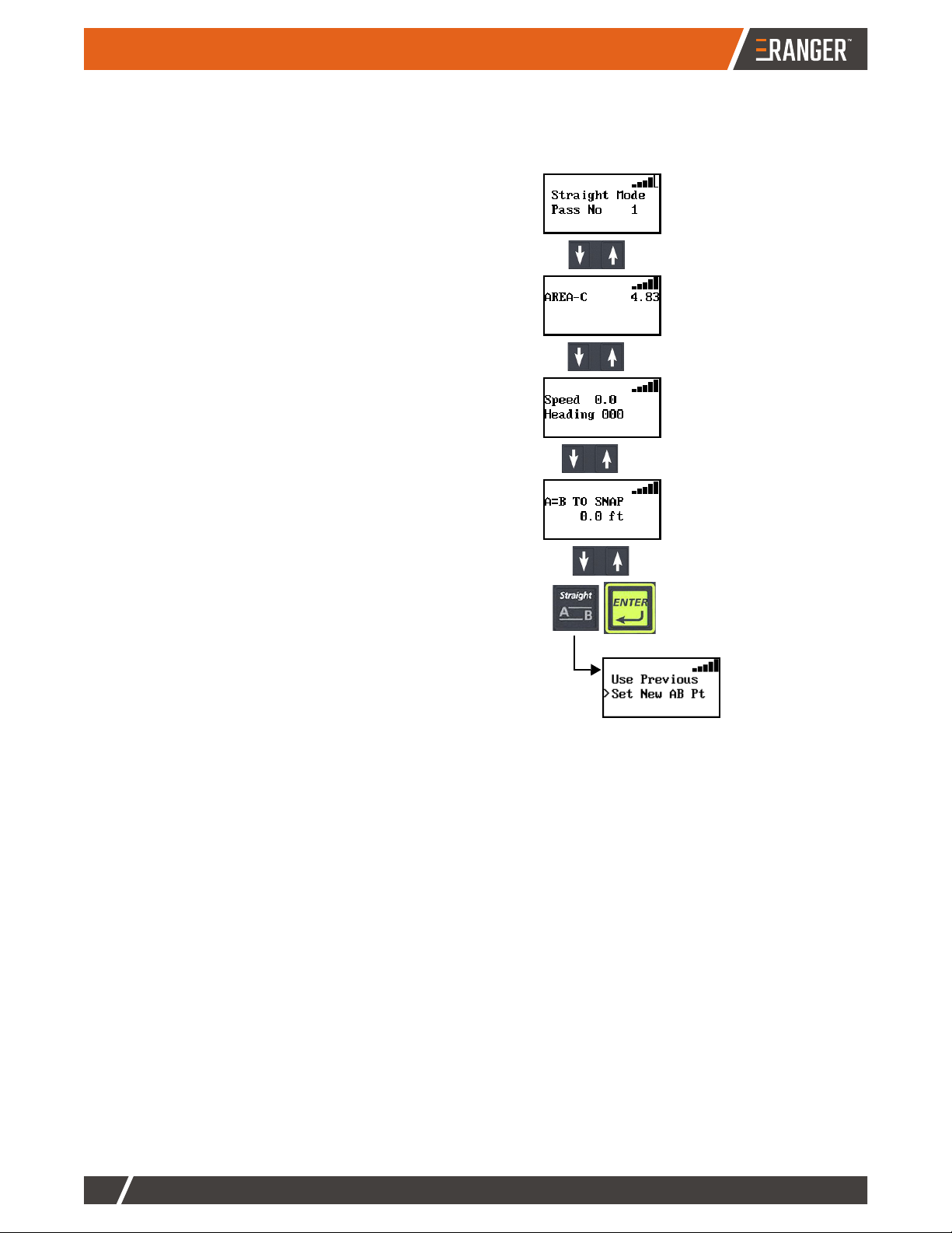
Displaying Field and Driving Information While Receiving Guidance
While in either Straight or Contour guidance mode, use the down/up arrows to display the following field and
vehicle information:
• Field area (calculated from driving a perimeter while in
Contour mode—see “Calculating the Area of a Field” on
page 15)
• Vehicle ground speed and heading (Speed units are
based on the Units of Measure setting—mph if units are
feet, kph if units are meters—see “Service Menu” on
page 12)
• Snap (A=B TO SNAP) distance—this screen appears only
if you are in Straight guidance mode and it enables you to
move (‘snap’) the A=B line to your current position (if you
are no longer on your A=B line)—see “Snapping the A=B
Line to Your Current Position” on page 15
Repeatedly pressing an arrow button cycles through the screens
at right; repeatedly pressing the other arrow button cycles
through the same screens in reverse order.
Straight mode
Press Straight to
generate parallel paths for
RANGER to follow (the
menu below appears)
Field area
Vehicle ground speed
and heading
Snap distance (for
A=B lines)
HANDSFREEFARM.COM
17
USING RANGER
Performing Additional Tasks with RANGER
RANGER provides additional functionality via menu items that are available upon pressing STOP Guidance.
Pausing then Resuming Guidance
Pause guidance when you need to stop logging data, such as during turns or when relocating to another section of
the field. This is useful during Contour guidance where you may want RANGER to suspend logging while driving
toward a different pass.
1. Press STOP Guidance. Do not select any available menu items.
2. To resume guiding and logging data, press Straight or Contour. RANGER prompts to use the previously
defined A=B line (Use Previous is selected on the menu).
3. Press ENTER to have RANGER provide guidance and start logging data.
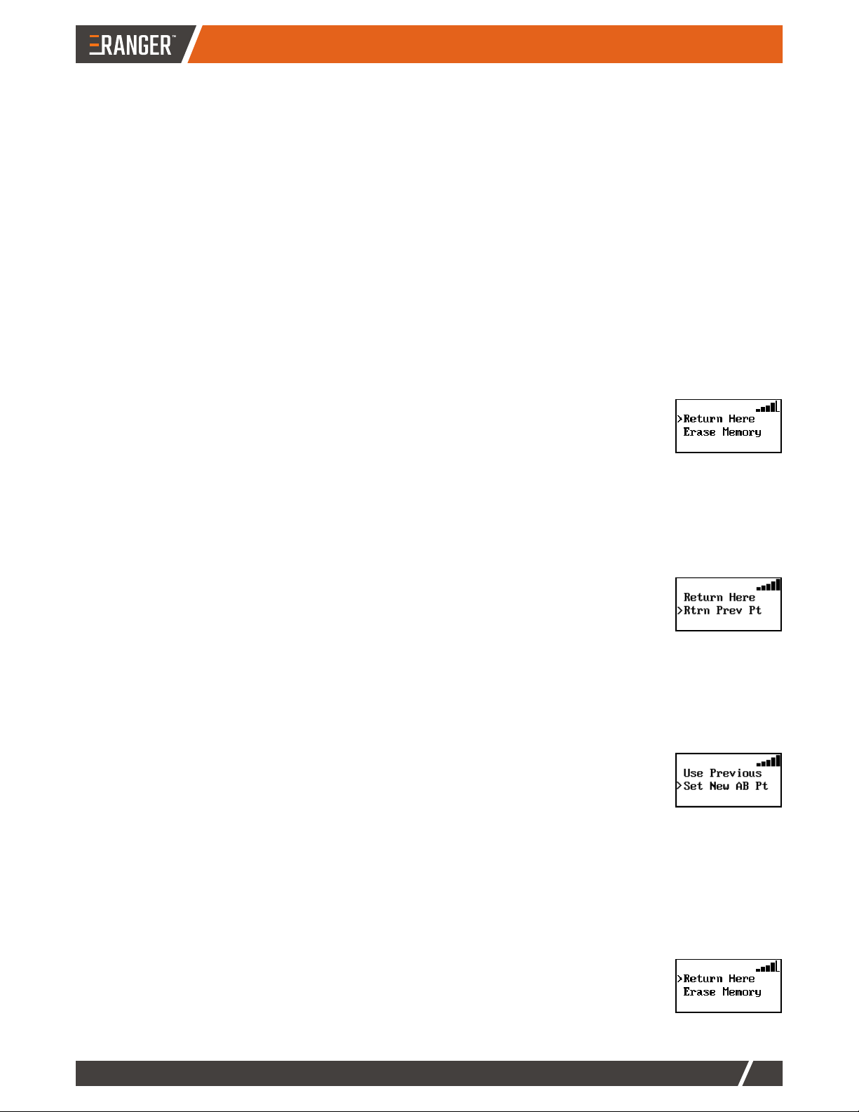
Saving a Return Point
Whether suspending application at a preferred stopping point (such as to reload product) or at the end the day, you
can save the job and record the end point so RANGER can later guide you to that stopping point.
1. Press STOP Guidance to stop guiding (stop logging data) and display additional menu items.
2. Press up arrow or down arrow until Return Here is selected, then press ENTER (Will
Guide Back To This Point appears onscreen).
3. (Optional) Press MENU to return to the ‘Ready’ screen.
Returning to a Saved Point
RANGER can guide you to a previously saved point, such as the point you needed to reload product to finish
working your field.
1. Press STOP Guidance to stop guiding (stop logging data) and display additional menu items.
2. Press down arrow until Rtrn Prev Pt is selected, then press ENTER. RANGER provides
guidance to the saved point (direction to turn and distance from point appear
onscreen).
3. When you have reached the saved point, press Straight or Contour. RANGER
prompts to use the previously defined A=B line (Use Previous is selected on the menu).
4. Press ENTER to have RANGER provide guidance and start logging data.
Switching Modes
You can switch from one guidance mode to the other.
1. While in one guidance mode (Straight or Contour), press the other guidance mode
button (Contour or Straight). RANGER displays menu options to use the previous
A=B line or to set a new one.
2. Use the down/up arrows to select your preferred option (Use Previous or Set New AB
Pt), then press ENTER.
Erasing Memory
Erasing memory removes all recorded passes and points for the job to prepare for a new job. You typically do this
at the end of each field. There are 30.56 hours of total memory available. If you do not erase memory between
fields, you may run out of memory during a job. If this happens, a ‘Memory Full’ message appears.
1. Press STOP Guidance.
2. Press down arrow until Erase Memory is selected then pres ENTER. ‘Erasing Swaths’
appears briefly then RANGER exits the menu (returns to ‘Ready’ screen).

USING RANGER
HANDSFREEFARM.COM
18
Support
Use the following sections to:
• Understand diagnostics information (below)
• Troubleshoot possible issue (page 19)
• Test antenna voltage or check DGPS position accuracy (page 20)
Diagnostics Menu
To display the Diagnostics menu, press
The following table provides helpful RANGER operating/
troubleshooting information.
Item Description
Correction Type Type of differential correction being used. RANGER supports two corrections types: SBAS
(default) and e-Dif. Use e-Dif when/where SBAS is unavailable.
Sats Number of GPS satellites currently visible in the sky (does not include correction satellites).
• Trk = number of satellites RANGER is tracking
• Use In Calc = number of tracked satellites used in the position calculation
STDEV Pseudo-estimate of the DGPS solution accuracy determined as the RMS value of the
positional residual errors. STDEV is valid only if six or more satellites are used in the solution
calculation. Typical values for SBAS correction are 0.15 m - 0.45 m (0.5 ft - 1.5 ft).
HDOP (Horizontal Dilution of Precision) Indicates the influence of the current GPS satellite
constellation geometry on the horizontal accuracy of the position solution. Lower values of
HDOP indicate better geometry. Typical valves are 0.8 - 2.0.
Diff Age Age (in seconds) of the DGPS corrections calculation. Optimal operating values are < 7 sec.
Bit Error Rate (Available only when SBAS is the correction type) Often abbreviated as BER, the bit error
rate is the relative strength of the correction satellites. Two numbers are shown separated by
a hyphen, where each number ranges from 0 to 500 with 0 being the best and 500 the worst.
If BER > 20 verify the antenna has a clear view of the sky to properly find and track
correction satellites.
GPS Software GPS software version.
App Software Application software version.
Serial Number RANGER console serial number.
Memory Amount of remaining memory (in hours). All passes are recorded in memory until erased at
the end of each field. To clear the memory, press STOP Guidance, press down arrow until
Erase Memory is selected, then press ENTER.
Diagnostics
Correction Type SBAS
Sats Trk=10, Use in Calc=09
STDEV 0.04 ft
HDOP 1.20
Diff Age 0001 secs
Bit Rate Error 0-0
GPS Software Ver. 6.8
App Software Ver. 1.0
Serial Number 300556
Memory 29.87 hr./98% Free
until
Diagnostics
is selected
Table of contents
Popular Farm Equipment manuals by other brands


Ag Leader Technology
Ag Leader Technology CaseIH 2055 manual

Nogueira
Nogueira HAYNOG-300 instruction manual

Duratech
Duratech HAYBUSTER 107 DRILL Operating Instructions and Parts Reference

Hisarlar
Hisarlar SB1150 User and maintenance manual

InterPuls
InterPuls PORTABLE IMILK401 Instruction Manual, Operation and Maintenance original instructions

Raven
Raven SmarTrax installation manual