Ag Leader Technology CaseIH 2055 User manual

Ag Leader Technology Parts List for Cotton Picker
CaseIH 2055
November 2002 8-1
NOTE: Indented items indicate parts
included in an assembly
Part name/Description Part No. Quantity
Instruction Kit – Case 2055 2006200-1 1
Arm Assy (18in rod, S-hook, 16 in. chain, spring) 2000311-2 1
Header Sensor – Standard 20003221-1 1
Cable Kit – Case 2055 2001238 1
Header Extension Cable – 18 in. 2000453-1 1
Sensor Distribution Cable – Case Monitor 2 Rows 2100006-1 1
Cotton Distribution Cable – 8 in. 2100007-1 1
Cotton F/G/P Cable – 4 ft 2100008-1 1
Cotton Cab Cable – Case 2055 2100010-1 1
Cable Inst. Kit – Cotton 2055 2000901-20 1
Drill Bit – Steel – 1/4 in. 2001001-25 1
Hole Saw – 1-3/8 in. 2001002-138 1
Silicone Rubber Adhesive Sealant – Black – 2.8 oz. 2001011 1
Fuse – Blade – 20 amp 2001012 1
Alcohol Swab Pack 2002811 2
Grey Plastic Cable Clamps 2002812 5
Cable Tie – 15 in. – Black 2002817-15 10
Cable Tie – 6 in. – Black 2002817-6 15
Adhesive Mounting Base – 2 way 2002821-2 5
Grommet – Rubber – 3/4 in. ID X1-3/8 in. PHD 2002824-75 1
Parts Kit Cotton – Case 2055 2001336-1 1
Header Sensor Inst. Kit – Generic, Case 2000330-4 1
Transfer Punch – 11/32 in. 2001003-34
File – Square – 5/16 in. 2001006 1
File Handle 2001019 1
Monitor Bracket Inst. Kit 2001304-9 1
Drill Bit – Tin Coated – 13/64 in. 2001000-20 1
Hex Hd Capscrew, Coarse Thd, Gr 5, ZP 1/4 x 3/4 in. 2002001-25075 2
Hex Nut, Coarse Thd, ZP 1/4 in. 2002051-25 2
Split Lockwasher, ZP 1/4 in. 2002061-25 2
Flat Washer, Standard, ZP 1/4 in. 2002071-25 4
Self Tapping Hex Slotted Hd Screw, Coarse Thd, Gr 5, 1/4 x 3/4 in. 2002075-25075 4
Fastener Kit – (1/2 in, 35 pcs) 2001337-1 1
Pen – Black – Permanent – Fine 2002813 1
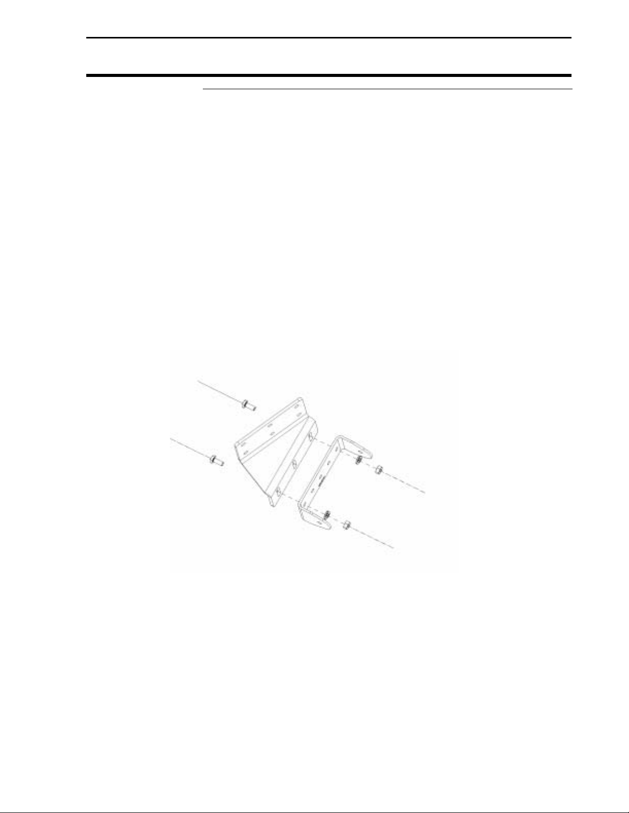
Post Bracket 3000693 1
Hood Adapter Assembly 2055 Outer Double 3000273 2

Parts List for Cotton Picker Ag Leader Technology
CaseIH 2055
November 2002
8-2
NOTE: Indented items indicate parts
included in an assembly
Part name/Description Part No. Quantity
Emitter Assembly – 5 Position 3000287 4
Serrated Flange Nut – SS, BZP, 1/4 in.-20 2002249-25 4
Emitter Sensor Assembly, 5 Lens 3000219 1
Sensor Plate – 5 Position 3000229 1
Gasket – 5 Lens 3000281 1
Lens Cover – 5 Lens 3000283 1
Detector Assembly – 5 Position 3000288 4
Serrated Flange Nut – SS, BZP, 1/4 in.-20 2002249-25 4
Emitter Sensor Assembly, 5 Lens 3000220 1
Sensor Plate – 5 Position 3000229 1
Gasket – 5 Lens 3000281 1
Lens Cover – 5 Lens 3000283 1

Ag Leader Technology Cotton Picker Installation
CaseIH 2055
November 2002 2006200-1 9-1
Important Notices
You will save time and prevent wrong installation of components by
closely following these step-by-step instructions. If you have any
questions call Ag Leader Technology at 515-232-5363.
Signal words (CAUTION, IMPORTANT and NOTE) are provided to
draw attention to information that is important for the safe/correct
installation and operation of this product.
• CAUTION – will alert you to situations that will impact the
physical safety of you or others.
• IMPORTANT – will alert you to the potential for damage to the
product or loss of data.
• NOTE – will provide you with additional information to simplify a
procedure or clarify a process.
Place the Installation Instructions and Parts List in their sections of the
Operator’s manual to prevent their loss or to use as reference after
completing installation.
Section Contents Item Page
Installing Monitor 9-2
Installing Cab Cable 9-5
Installing Switched Power, Fan Speed, Ground Speed
Cable 9-8
Installing GPS Coax Cable 9-9
Installing Hood Adapters 9-11
Installing Flow Sensor and Sensor Cable 9-14
Installing Header Sensor. 9-16
Final Inspection 9-18
***

Parts List for Cotton Picker Ag Leader Technology
CaseIH 2055
November 2002 2006200-1
9-2
Installing Monitor
in Cab
Parts required for this procedure:
• Monitor Unit
• Post Bracket
• U-Bracket
• Screw-mount cable-tie base, mounting screw and cable ties.
• Monitor Bracket Install Kit (screws, bolts, washers and nuts)
Step-by-Step
Procedure 1. Using the hardware from the monitor install kit, attach the post
bracket to the u-bracket as shown in Figure 1.
NOTE: If installing a YM2000, PF3000 or PF3000 Pro monitor,
mount the u-bracket in the same position as shown in Figure 1.
Figure 1: Monitor Bracket Assembly
2. Position the post bracket assembly along the center cab post on the
right side of cab below mirror (if mirror is present). Move the
assembly up or down to obtain the optimum position for your
viewing. Figure 2 is the recommended location for all monitors.

Ag Leader Technology Cotton Picker Installation
CaseIH 2055
November 2002 2006200-1 9-3
Figure 2: Bracket Mounting Location (with mirror)
3. Using the post bracket as a template, mark the two mounting holes
on the cab post. A third hole can be drilled through the bracket and
post for additional support. The mounting bracket assembly is
shown in Figure 3 in the correct location on the cab post (if no
mirror is present).
Figure 3: Post Bracket Mounting (without mirror)

Parts List for Cotton Picker Ag Leader Technology
CaseIH 2055
November 2002 2006200-1
9-4
4. Center punch and drill the mounting holes with the provided 13/64
inch drill bit.
5. Attach the post bracket to the cab post with three 1/4x3/4 inch self-
tapping screws.
6. Reattach the u-bracket to the post bracket (See Figure 1).
7. Mount the monitor in the bracket.

Ag Leader Technology Cotton Picker Installation
CaseIH 2055
November 2002 2006200-1 9-5
Installing Cab and
Distribution
Cables
Parts required for this procedure:
• Distribution Cable
• Cab Cable
Step-by-Step
Procedure 1. Remove the interior panel at the front of the right hand console secured by
three wing nuts. This will expose the hole that the cab cable needs to pass
through.
2. Remove the exterior access panel on the right hand side of the cab. See Figure
5.
Figure 5 Exterior Access Panel
3. From the outside of the cab, push the 25-pin end of the cab cable through a
large opening towards the front of the compartment.
4. Route the cable up along the backside of the right front window.
5. Pull enough length to allow you to route the cable up over the right rear of the
monitor bracket and back down to the 25-pin connector on the monitor. This
will keep the cable from interfering with the operator’s field of vision.
IMPORTANT: Never use force to mate electrical connectors. If the
connectors do not push together easily, they are not aligned properly.
Using force will only result in damage to the connectors.
6. Connect the cab cable to the monitor.
Exterior Access
Panel

Cotton Picker Installation Ag Leader Technology
CaseIH 2055
November 2002 2006200-1
9-6
7. Cable clamps may be used to secure the cable to the window.
8. From the exterior access panel, route the 24-pin connector end of the cab cable
towards the back wall of the cab.
9. On the rear of the cab wall, to the right of the diode module and just below the
cab relay drill a 1-3/8 in. hole with the hole saw. See Figure 6.
NOTE: Ensure that none of the existing bolts in the cab wall will interfere
with the flange of the 24-pin connector before drilling the 1-3/8 in. hole.
Figure 6. 1-3/8 inch hole for 24-pin connector.
10. With the distribution cable inside the cab, push the six connectors through the
hole starting with the largest to the smallest.
11. Place rubber grommet around wires and push grommet into hole.
IMPORTANT: Never use force to mate electrical connectors. If the
connectors do not push together easily, they are not aligned properly.
Use of force on connectors will result in connector damage.
12. Connect distribution cable to cab cable. Ensure they are aligned before
pushing them together.
1-3/8 inch hole

Ag Leader Technology Cotton Picker Installation
CaseIH 2055
November 2002 2006200-1 9-7
Figure 7. Junction Block
13. Seal the area around the grommet with the provided black silicone sealant as
needed.
14. At the junction block on the bottom left of the back cab wall, attach the long
pigtail with ring connector and 5-amp fuse to either terminal of the junction
box. See Figure 7.
A
ttaching location for
pigtail.

Cotton Picker Installation Ag Leader Technology
CaseIH 2055
November 2002 2006200-1
9-8
Installing
Switched Power,
Fan Speed,
Ground Speed
Cable
Parts required for this procedure:
• Switched power, Fan Speed, Ground Speed (FGP) cable (identified by a 9-pin
tee connector on one end and a 4-pin shroud on the other end)
Step-by-Step
Procedure NOTE: When facing the exposed access panel on the exterior of the cab,
the digital tachometer is located towards the top on the right hand side.
1. Disconnect the existing 9-pin connector plugged into the digital tachometer.
Figure 8. 9-Pin connector attached.
2. Tee the 9-pin end of the FGP cable into the existing wiring harness of the
digital tachometer.
NOTE: Attach the 4-pin shroud end of the FGP cable into the short 4-pin
tower connector towards the 24-pin end of the cab cable.
Digital
Tachometer

Ag Leader Technology Cotton Picker Installation
CaseIH 2055
November 2002 2006200-1 9-9
Figure 9. FGP cable attached to cab cable.
Installing GPS
Coax Cable
Parts required for this procedure:
• 10 ft coax cable used inside the cab
• 15 ft coax cable used to connect the antenna to bulkhead connector
• Bulkhead connector
Step-by-Step
Procedure 1. Drill a 1/2-in. hole in the space below the diode module towards the left side of
the cab wall. See Figure 10.
FGP Cable

Cotton Picker Installation Ag Leader Technology
CaseIH 2055
November 2002 2006200-1
9-10
Figure 10. GPS bulkhead connector installed.
2. Position the 10-ft coax so the right angle connector attaches to the monitor and
the other end attaches to the bulkhead connector. Attach 10-ft coax cable.
Route the coax with the cab cable. Fasten with cable ties of secure.
3. Any excess cable should be looped and tied at the back of the cab just above
the bulkhead connector.
4. Route the 15-ft coax cable from the bulkhead connector to the antenna located
on the front center of the cab.
5. Use cable ties and adhesive backed anchors to secure the coax cable to the cab.
6. Replace the interior and exterior access panels.
Bulkhead
Connector

Ag Leader Technology Cotton Picker Installation
CaseIH 2055
November 2002 2006200-1 9-11
14-1/4 inch
Measurement
Installing Hood
Adapters
Part required for this procedure:
• Sensor Install Kit
• 9/32 in. drill bit
• Electric drill or hand punch
Step-by-Step
Procedure 1. Remove the double outer hoods from the picker by loosening the four nuts
holding the hood and chute together.
2. From the bottom of all four sides, measure up 14-1/4 inches and mark. Ensure
the bottom of the chute is square and not bent.
3. With a square, extend the marks around the chute. This identifies the section of
the chute to be removed. See Figure 11.
Figure 11. 14-1/4 inch measurement on chute.

Cotton Picker Installation Ag Leader Technology
CaseIH 2055
November 2002 2006200-1
9-12
4. Use a saber saw, plasma cutter or any good cutting device to cut along the
inside of the marks.
5. Use a file to remove burrs and rough edges.
6. Place the hood adapter flanges inside the hood. Mark the 14 hole positions on
hood.
7. Center punch and drill the marks with a 9/32-inch drill bit. Use a rat-tail file to
remove any burrs. See Figure 12.
Figure 12. Holes for hood adapter.

Ag Leader Technology Cotton Picker Installation
CaseIH 2055
November 2002 2006200-1 9-13
8. Attach the hood adapter to the hood using the flange nuts and truss head bolts
provided.
NOTE: The flange nuts should be on the outside of the hood so it doesn’t
protrude into the flow of the cotton. If bolts are installed wrong, errors
could be caused in yield data.
9. Repeat Steps 2 through 8 and install the hood adapter on the other hood.
10. Re-install the hoods on picker.

Cotton Picker Installation Ag Leader Technology
CaseIH 2055
November 2002 2006200-1
9-14
Installing Flow
Sensors and
Sensor Cable
Parts required for this procedure:
• Four, 5 Position Emitters
• Four, 5 Position Detectors
• Sensor Distribution Cable
• Installation Kit
Description Emitter – sensor block that is thicker and has a right angle connector coming out of
the top cover with a two foot long cable.
Detector – sensor block that is thinner and has an AMP 14-pin connector mounted
on the back cover.
Step-by-Step
Procedure 1. Install the emitters on the front side of the hood adapters. Ensure the captive
nuts are tight so no vibration can occur to the sensor. See Figure 13.
2. The detectors should be installed on the backside of the hoods or side towards
the basket.
Figure 13. Emitters installed on hood.

Ag Leader Technology Cotton Picker Installation
CaseIH 2055
November 2002 2006200-1 9-15
3. Start routing the sensor distribution cable at the right side of the picker. Ensure
to get the correct end of the cable. It has an extended cable with the AMP
CP14 pin, which will run to the main distribution cable on the backside of the
cab.
4. Connect the AMP 14 pin connector into the back of each of the detectors
starting at the right side so they are in order on the monitor. Row 1 is on the
left side of the machine.
5. Tie the sensor distribution cable to the monkey bars directly below the sensors
with as many ties as needed.
6. Connect all emitters and detectors pairs together using the 4-pin connection as
seen in Figure 14.
Figure 14. Connect Emitter and Detector.
7. Route the single sensor cable from the far right side to the back of the cab
where the main distribution cable is located.
8. Connect the 14-pin connector of the sensor cable to the distribution cable.
Connector
Detector Emitter

Cotton Picker Installation Ag Leader Technology
CaseIH 2055
November 2002 2006200-1
9-16
Installing Header
Sensor
Parts required for this procedure:
• Header Sensor
• Threaded Arm Assembly
• Drill bit
Step-by-Step
Procedure 1. Attach threaded rod assembly to sensor pivot on the header sensor.
2. Refer to Figure 15 and position the header sensor on the cab support beam.
IMPORTANT: To prevent damage to the picker or header sensor,
ensure you position the header sensor so there it is clear of the light and
hoses.
3. Use the header sensor as a template to mark and center punch holes for
mounting the header sensor.
4. Use a 11/32inch-drill bit and drill mounting holes. See Figure 16.
Figure 15. Positioning Header Sensor

Ag Leader Technology Cotton Picker Installation
CaseIH 2055
November 2002 2006200-1 9-17
Mounting Holes
Existing Bolt
Figure 16. Header Sensor mounting holes.
5. Attach header sensor with two 5/16 x 1-inch hex head cap screws.
6. Attach S-hook to existing bolt on the back of the center picking unit. See
Figure 17.
Figure 17. Existing bolt on picking unit.

Cotton Picker Installation Ag Leader Technology
CaseIH 2055
November 2002 2006200-1
9-18
Figure 18. Header Sensor installed.
7. Connect header sensor cable to distribution cable. Tie up extra cable away from
moving parts.
8. You will have to use the 18-inch header extension cable to reach the distribution
cable properly.
Final Inspection
Installation is now complete. Do a walk around of the cotton picker and complete
the following:
• All cable connections have been made.
• Excess cable has been tied out of the way, so there is not interference.
• All tools have been removed from the cotton picker.
• All cap screws and carriage bolts are tight.
Table of contents
Other Ag Leader Technology Farm Equipment manuals