DEUTZ-FAHR SwatMaster 7131 User manual
SwatMaster 7131
SwatMaster 7131 Evo
Assembly instructions
Edition 9.2008
Date printed 9.2008
Language EN
Machine number 5801 - / 1001 -
Type 6962 Evo / 6962
Document Number VF16645615.EN

Copyright by Kverneland Group Gottmadingen N. V. , Germany. Reproduction, transfer to other media, translation or the use of extracts or parts
of this manual without the explicit permission of Kverneland, is not permitted. All rights reserved. The contents of these assembly instructions are
subject to change without notice. The right to technical revision is reserved.
Kverneland Group Gottmadingen N. V.
Filiale Gottmadingen
Industriepark 312
78244 Gottmadingen
Germany
Tel.: +49 7731 788 - 0
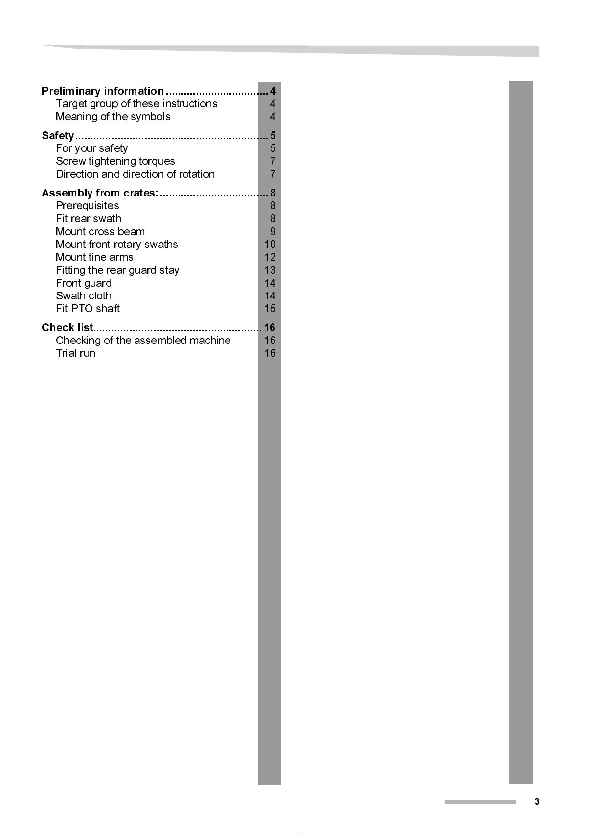
Table of contents
3
Tabl e of conten ts
Preliminary information ..................................4
Target group of these instructions 4
Meaning of the symbols 4
Safety................................................................5
For your safety 5
Screw tightening torques 7
Direction and direction of rotation 7
Assembly from crates:....................................8
Prerequisites 8
Fit rear swath 8
Mount cross beam 9
Mount front rotary swaths 10
Mount tine arms 12
Fitting the rear guard stay 13
Front guard 14
Swath cloth 14
Fit PTO shaft 15
Check list........................................................16
Checking of the assembled machine 16
Trial run 16

4
Preliminary information
Prel imi nary informat ion
Target group of
these instructions
These instructions are directed at qualified skilled technicians and
those with other qualifications in the field of agricultural technology.
For your safety
Prior to assembly familiarize yourself with the content of these assem-
bly instructions.
The employer should:
Untrained or unauthorized individuals are not permitted to assemble
the machinery.
Meaning of the
symbols
In order to make this manual clear and easy to read, we have used
various symbols. They are explained below:
•
A dot accompanies each item in a list
>
A triangle indicates operating functions which must be performed
We have also used pictograms to help you find instructions more
quickly:
N
OTE
“Note” indicates tips and notes for the operation.
The warning triangle indicates important safety instructions. Failure to
observe these safety instructions can result in:
•
Serious operational faults for the machinery;
•
Damage to the machinery;
•
Personal injury or accidents.

Safety
5
Safety
For your safety
Read and pay close attention to the safety instructions in this chapter
prior to assembling the machinery. Everyone involved in assembling
or installing this machine has to read and pay close attention to the fol-
lowing assembly instructions.
Warning triangles indicate the risk of serious injuries or death. When-
ever you come across these signs in the assembly instructions, please
make sure that you implement all appropriate safety measures.
They also indicate the risk of damage to the machinery as well as fi-
nancial and legal consequences (i.e. invalidation of the warranty, or le-
gal liability).
Faulty assembly or misuse results in:
•
Danger to life and limb of the operator, third parties, and animals in
the vicinity of the machine,
•
Damage to the machine and other property belonging to the oper-
ator or third parties
•
Negative effects on the efficient and faultless operation of the ma-
chine.
Assembly in
accordance with
assembly
instructions
Non-compliance with the following rules amounts to gross negligence!
It invalidates any liability of the manufacturer for resultant damage.
Non-compliance is solely at the risk of the operator!
This machine must only be assembled by trained technicians in ac-
cordance with the current revision of the assembly instructions. Before
the machine is coupled to a tractor, transported, or commissioned, the
operating manual and its safety instructions have to be thoroughly
read and followed.
It is the responsibility of the proprietor to ensure that all personnel in-
volved in the assembly are provided with the relevant accident preven-
tion regulations, as well as generally applicable health and safety and
road safety regulations. All personnel involved in the assembly have
to be aware of these rules and regulations and adhere to them; they
also have to be instructed on the potential risks and dangers.
Unauthorized alterations to the machine invalidate any liability of the
manufacturer for resultant damage.
The following rules and regulations have to be observed:
•
Relevant accident prevention regulations pertaining to the locality,
•
Generally recognized health and safety regulations as well as road
traffic legislation,
•
Functional limits and safety regulations as set out in the technical
operating manual,

6
Safety
General safety and
accident prevention
regulations
•
Responsibilities for the various activities have to be clearly allocat-
ed and adhered to. There must not be any confusion regarding re-
sponsibilities, otherwise the safety of the assembly personnel is
put at risk.
•
Before you start work, familiarize yourself with all the fittings and
actuation elements and their functions.
•
For all work on the machine, use only appropriate tools and imple-
ments in perfect condition.
•
You must only use parts (accessories, lubricants etc.) which com-
ply with the minimum manufacturer's specifications; you must use
them in accordance with regulations (including specified torques).
•
A part complies with the requirements, if it is an original replace-
ment part or if it carries the explicit endorsement by the manufac-
turer of the original machine.
•
Wear close-fitting clothes when operating the machine! Wear stur-
dy footwear and regulation protective equipment!
•
Chock and secure the machine carefully during assembly!
•
Particular care has to be taken in dealing with energy accumulators
such as springs and hydraulic or compressed air aggregates.
•
Dispose of oils, grease, and filters in accordance with regulations!
•
Protective equipment has to be properly fitted and swivelled into
their protective position.
•
Actuation elements (ropes, chains, and rod-assemblies) of remote-
ly controlled fittings have to be installed in such a way that they
cannot cause unintended movement in any transport or operating
position.
•
Do not leave the engine running inside enclosed buildings!
•
All remote-powered and all other movable parts (e.g. hydraulics)
have pinch or shear points!
•
Pay close attention to the markings on reversible connections and
be aware of the risk of transposition.
•
Always turn off the power supply before working on the electrical
system.
•
When carrying out electric welding, always disconnect the genera-
tor and battery cables!
Safety
7
Screw tightening
torques
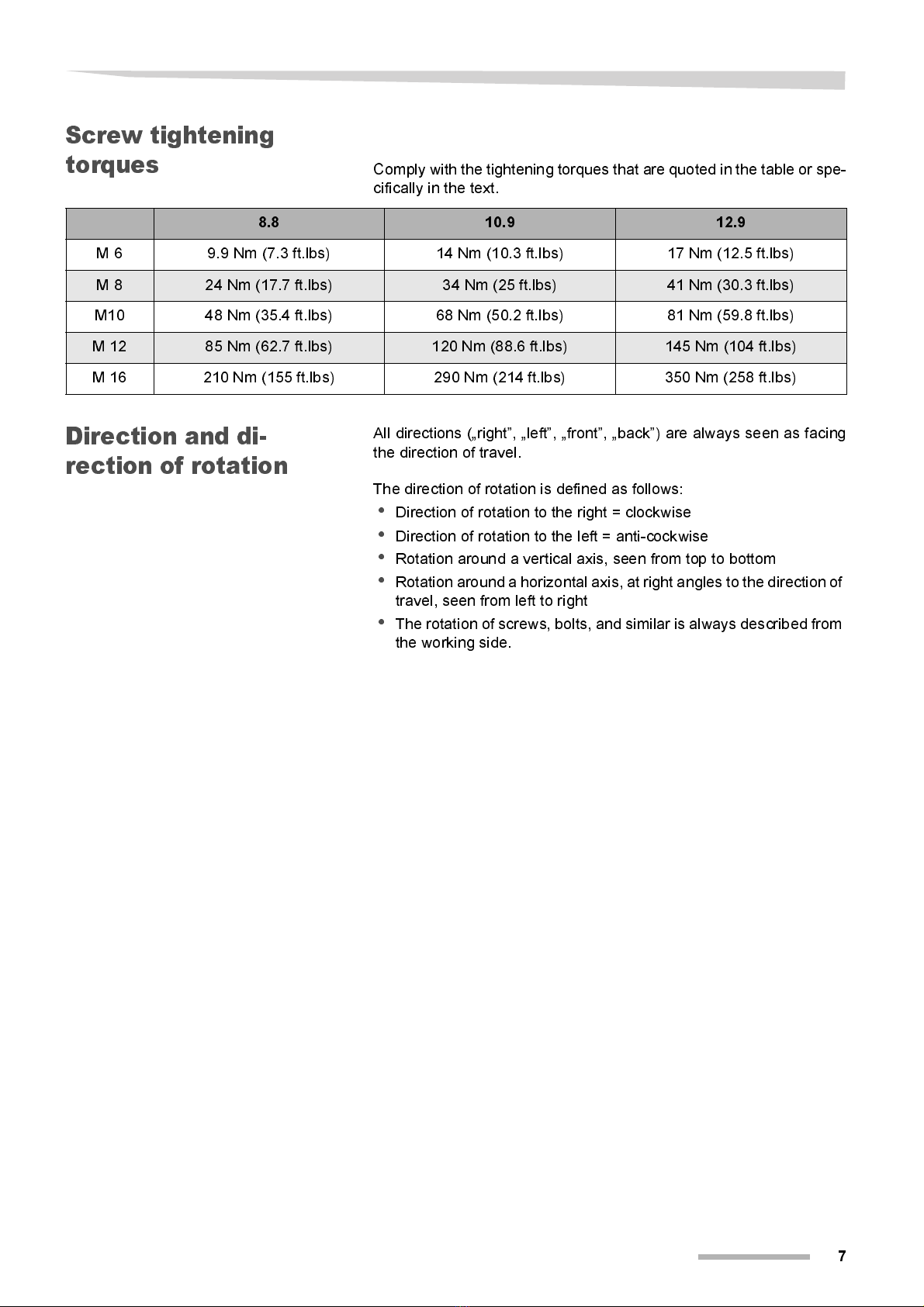
Comply with the tightening torques that are quoted in the table or spe-
cifically in the text.
Direction and di-
rection of rotation
All directions („right”, „left”, „front”, „back”) are always seen as facing
the direction of travel.
The direction of rotation is defined as follows:
•
Direction of rotation to the right = clockwise
•
Direction of rotation to the left = anti-cockwise
•
Rotation around a vertical axis, seen from top to bottom
•
Rotation around a horizontal axis, at right angles to the direction of
travel, seen from left to right
•
The rotation of screws, bolts, and similar is always described from
the working side.
8.8 10.9 12.9
M 6 9.9 Nm (7.3 ft.lbs) 14 Nm (10.3 ft.lbs) 17 Nm (12.5 ft.lbs)
M 8 24 Nm (17.7 ft.lbs) 34 Nm (25 ft.lbs) 41 Nm (30.3 ft.lbs)
M10 48 Nm (35.4 ft.lbs) 68 Nm (50.2 ft.lbs) 81 Nm (59.8 ft.lbs)
M 12 85 Nm (62.7 ft.lbs) 120 Nm (88.6 ft.lbs) 145 Nm (104 ft.lbs)
M 16 210 Nm (155 ft.lbs) 290 Nm (214 ft.lbs) 350 Nm (258 ft.lbs)

8
Assembly from crates:
Assemb ly from crates:
Prerequisites
Select a suitable level surface of about 10m x 10m for the assembly.
Lifting gear with lifting attachments capable of lifting at least 1500 KG.
Supports to bear machine parts securely
Spanners to tighten screws.
Open crate
>
Put the crate on level ground and open it without damaging the contents.
>
Remove loose parts (wheels, boxes), and clear the space around larger
components.
Do not connect hydraulic control units
Do not connect hydraulic lines.
Hydraulic cylinders activated during the assembly can cause damage
to the machine.
Fit rear swath
>
Remove fastenings (wires, lashing straps) and take rear swath assembly
out of the crate. Stop points are indicated by arrows on the illustration.
>
Place the rear swath assembly securely on supports
Tandem axles
>
Mount wheels on tandem axle
Observe torques
Tighten wheelnut only to 20 Nm. Higher torques damage the plastic
washer
Stop points
20 Nm Plastic washer
Assembly from crates:
9
>
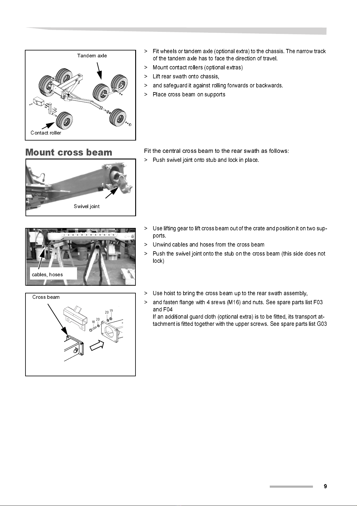
Fit wheels or tandem axle (optional extra) to the chassis. The narrow track
of the tandem axle has to face the direction of travel.
>
Mount contact rollers (optional extras)
>
Lift rear swath onto chassis,
>
and safeguard it against rolling forwards or backwards.
>
Place cross beam on supports
Mount cross beam
Fit the central cross beam to the rear swath as follows:
>
Push swivel joint onto stub and lock in place.
>
Use lifting gear to lift cross beam out of the crate and position it on two sup-
ports.
>
Unwind cables and hoses from the cross beam
>
Push the swivel joint onto the stub on the cross beam (this side does not
lock)
>
Use hoist to bring the cross beam up to the rear swath assembly,
>
and fasten flange with 4 srews (M16) and nuts. See spare parts list F03
and F04
If an additional guard cloth (optional extra) is to be fitted, its transport at-
tachment is fitted together with the upper screws. See spare parts list G03
Contact roller
Tandem axle
Swivel joint
cables, hoses
Cross beam
10
Assembly from crates:
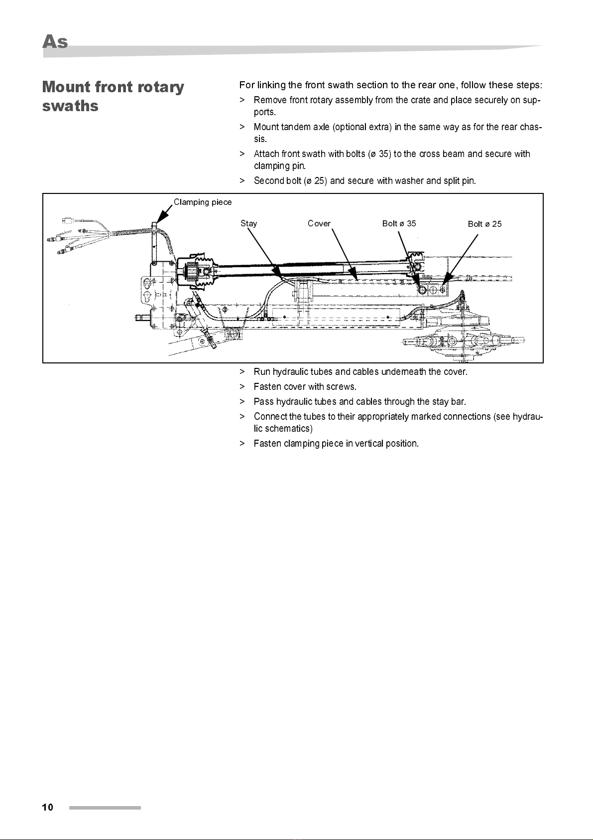
Mount front rotary
swaths
For linking the front swath section to the rear one, follow these steps:
>
Remove front rotary assembly from the crate and place securely on sup-
ports.
>
Mount tandem axle (optional extra) in the same way as for the rear chas-
sis.
>
Attach front swath with bolts (ø 35) to the cross beam and secure with
clamping pin.
>
Second bolt (ø 25) and secure with washer and split pin.
>
Run hydraulic tubes and cables underneath the cover.
>
Fasten cover with screws.
>
Pass hydraulic tubes and cables through the stay bar.
>
Connect the tubes to their appropriately marked connections (see hydrau-
lic schematics)
>
Fasten clamping piece in vertical position.
Bolt ø 35 Bolt ø 25
CoverStay
Clamping piece

Assembly from crates:
11
Hydraulic circuit diagram, 3-way ball valve
Clamping piece
12
Assembly from crates:
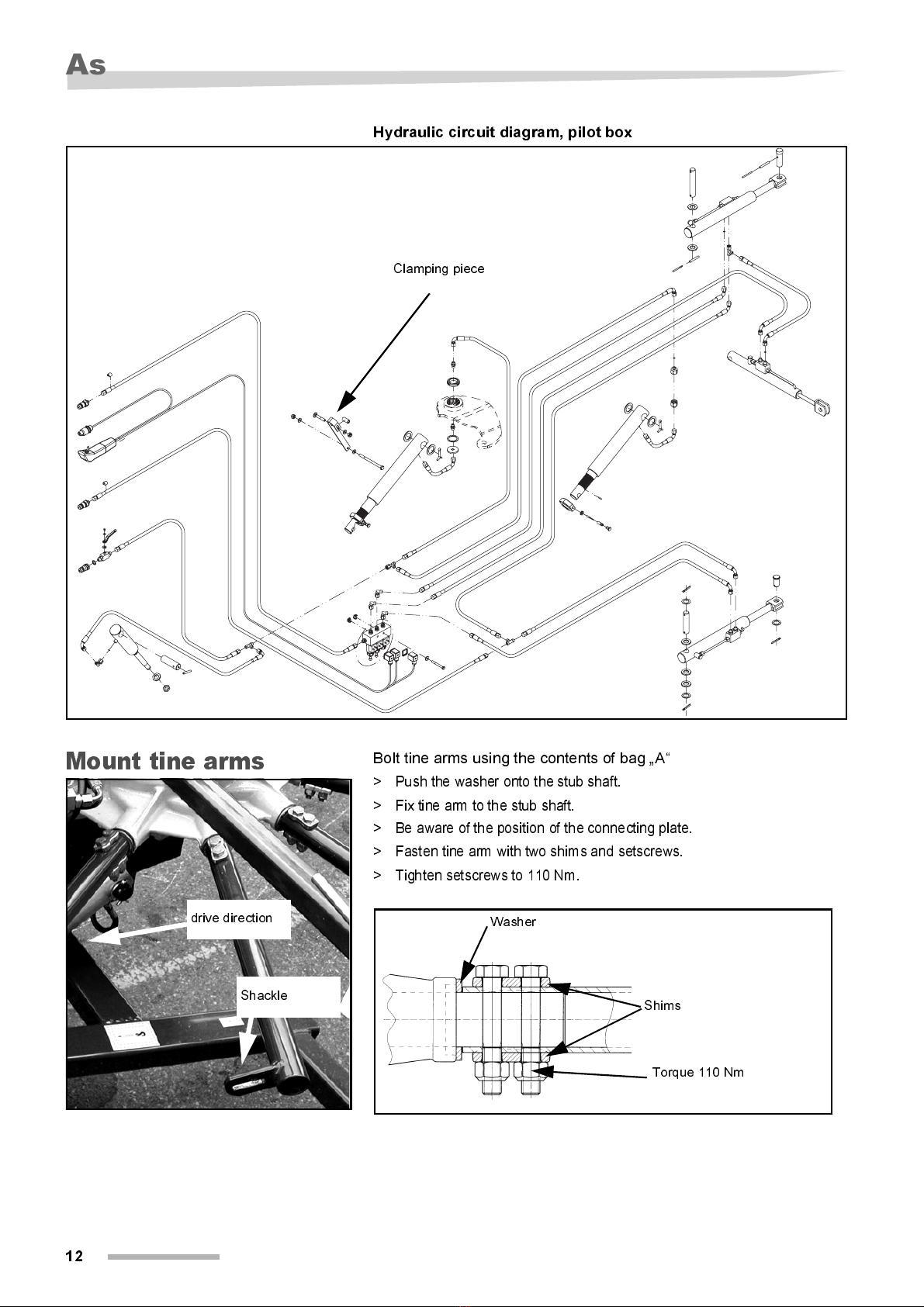
Hydraulic circuit diagram, pilot box
Mount tine arms
Bolt tine arms using the contents of bag „A“
>
Push the washer onto the stub shaft.
>
Fix tine arm to the stub shaft.
>
Be aware of the position of the connecting plate.
>
Fasten tine arm with two shims and setscrews.
>
Tighten setscrews to 110 Nm.
Clamping piece
drive direction
Shackle
Torque 110 Nm
Shims
Washer
Assembly from crates:
13
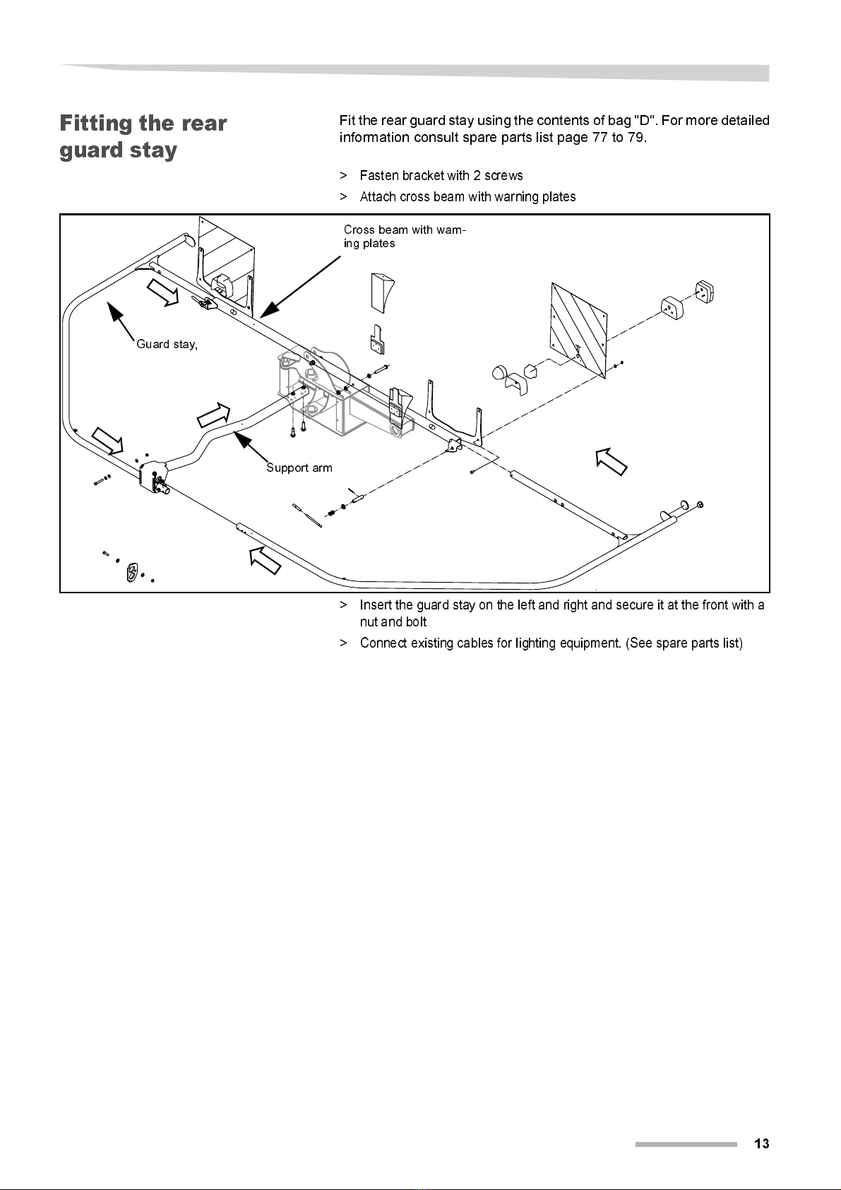
Fitting the rear
guard stay
Fit the rear guard stay using the contents of bag "D". For more detailed
information consult spare parts list page 77 to 79.
>
Fasten bracket with 2 screws
>
Attach cross beam with warning plates
>
Insert the guard stay on the left and right and secure it at the front with a
nut and bolt
>
Connect existing cables for lighting equipment. (See spare parts list)
Support arm
Cross beam with warn-
ing plates
Guard stay,
14
Assembly from crates:
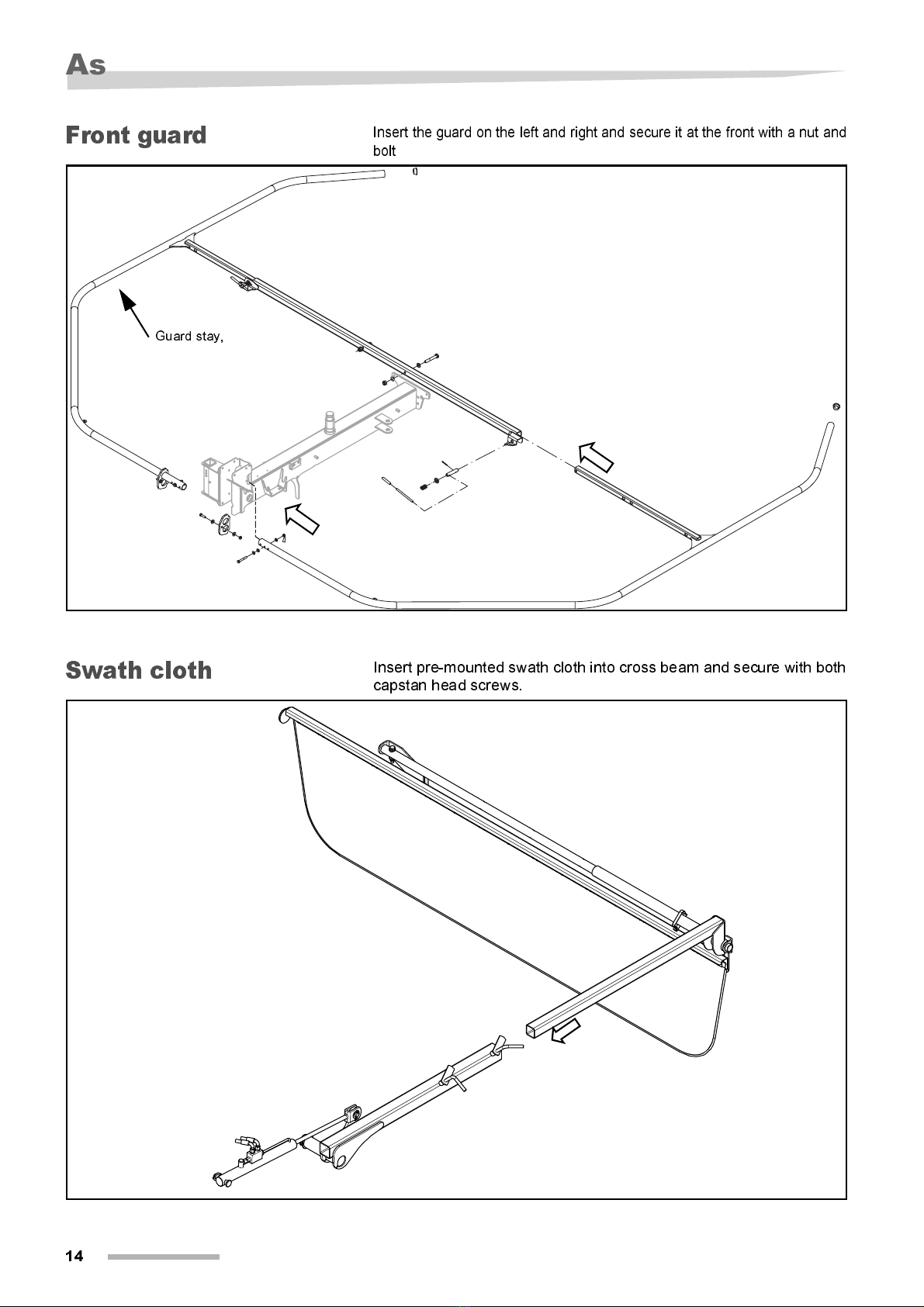
Front guard
Insert the guard on the left and right and secure it at the front with a nut and
bolt
Swath cloth
Insert pre-mounted swath cloth into cross beam and secure with both
capstan head screws.
Guard stay,

Assembly from crates:
15
Fit PTO shaft
Loosen the PTO drive shaft guard to insert the prop shaft.
>
Remove lockscrew (c) between the protecting tube (b) and the guard cone
(a)
>
Turn guard cone (a) and tube (b), until the „noses“ of slide ring (d) are lo-
cated above the recesses of the guard cone (arrows).
>
Push back guard cone and protecting tube
>
Push pivot (e) onto the stub shaft. Ensure that it is safely engaged (f).
>
Reverse the above instructions to fasten PTO drive shaft guard.
Torque limiting
clutch
Mount the PTO shaft with torque limiting clutch as illustrated.
Guard stay,
16
Check list
Check list
Checking of the
assembled
machine
Upon completion of assembly check the following:
>
Check all fastening torques (see table below).
>
Tighten all capstan head screws
>
Tighten all hydraulic connections
>
Safe run of hydraulic tubes and cables.
>
Safe connection of all cables.
>
PTO drive shaft connections engaged
>
Check lights
>
Check air pressure (1.5 bar)
Trial run
To fill the hydraulic system with oil requires about 3 litres of hydraulic
oil (SAE 90 API GL4).
Keep slewing range clear
Nobody must be within the slewing range of the machine. Moving parts
can cause injuries.
>
Operate all hydraulic functions of the machine ten times to the limit stops,
in order to remove any air from the system.
>
Upon completion check hydraulic system for leakages
This manual suits for next models
1
Table of contents
Other DEUTZ-FAHR Farm Equipment manuals


Popular Farm Equipment manuals by other brands

Schaffert
Schaffert Rebounder Mounting instructions

Stocks AG
Stocks AG Fan Jet Pro Plus 65 Original Operating Manual and parts list

Cumberland
Cumberland Integra Feed-Link Installation and operation manual

BROWN
BROWN BDHP-1250 Owner's/operator's manual

Molon
Molon BCS operating instructions

Vaderstad
Vaderstad Rapid Series instructions


