HandyWave HandyPort-Serial HPS-120 User manual
HPS-120
HandyPort-Serial
Wireless Solutions in your Hand
User’s Manual
Version 2.0

2
Table of Contents
1. INTRODUCTION.................................................................................................................... 3
1.1. FEATURES.........................................................................................................................3
1.2. PACKAGE..........................................................................................................................3
2. SPECIFICATIONS ................................................................................................................. 4
2.1. GENERAL.......................................................................................................................... 4
2.2. RS-232 INTERFACE...........................................................................................................5
2.2.1. Pin-out.........................................................................................................................5
2.2.2. Signals.........................................................................................................................5
2.3. FACTORY SETTINGS ..........................................................................................................5
2.4. STATUS LED.....................................................................................................................6
2.5. RESET BUTTON.................................................................................................................6
2.5.1. Entering the Configuration Mode ................................................................................6
2.5.2. Exiting the Configuration Mode...................................................................................6
2.5.3. Re-connection ............................................................................................................. 6
3. HARDWARE INSTALLATION............................................................................................... 7
3.1. HARDWARE DESCRIPTION.................................................................................................. 7
3.2. POWER SUPPLY ................................................................................................................ 7
3.3. INSTALL PROCEDURE.........................................................................................................7
4. USAGE...................................................................................................................................8
4.1. HYPER TERMINAL SETTINGS .............................................................................................. 8
4.2. CONFIGURATION................................................................................................................8
4.2.1. Starting Configuration..................................................................................................8
4.2.2. Usage Printing.............................................................................................................8
4.2.3. After Configuration ......................................................................................................8
4.3. COMMAND SET .................................................................................................................9

3
1. Introduction
Thank you for purchasing a HandyPort-Serial. The HandyPort-Serial can be used as a
component in many types of systems allowing them to communicate wirelessly with other
Bluetooth products such as PC-cards, laptops, handheld computers, mobile phones and other
HandyPort-Serial. The HandyPort-Serial is a suitable component in new products as well as in
existing products.
1.1. Features
No need of external host and software
Easy of installation and use
Supports configuration of the local device
Supports configuration of the remote device via Over-the-Air
Easy of maintenance
Supports up to 100 meter (Line of Sight)
1.2. Package
HPS-120 2 EA
Antenna 2 EA
A USB Cable for Power Supply
A Manual1
1This manual is required the software version 2.0 or above. If you have any more questions,
please contact us.
HandyWave Co., Ltd.
#604, 912, Seongnamdaero, Bundang-gu, Seongnam-si, Gyunggi-do, 463-827, South Korea
Tel: 82-31-709-8900, Fax: 82-31-708-9455
http://www.handywave.com/index3.htm

4
2. Specifications
2.1. General
Baud Rate Up to 115.2kbps (Recommend above 2.4kbps)
Supports 1.2/2.4/4.8/9.6/19.2/38.4/57.6/115.2kbps
Coverage Up to 100 M
Connection Point-to-Point
Signal DCD, TxD, RxD, GND, CTS/DSR1, DTR, RTS
RS-232 Interface D_SUB 9 Pin Female
Frequency 2.400 ~ 2.4835GHz
Tx. Power Max 20 / Typical 16dBm (Class 1)
Rx. Sensitivity -84dBm
Antenna Interface SMA Female
Antenna Gain Max. 2dBi
Power Supply +5 ~ +12Vdc
Current
Consumption
Max. 110mA
Operation
Temperature
-20 ~ 75 °C
Size 35mm (W) x 65mm (D) x 16mm (H)
1The default hardware configuration is for using CTS. If you want to use DSR, please contact
us.
5
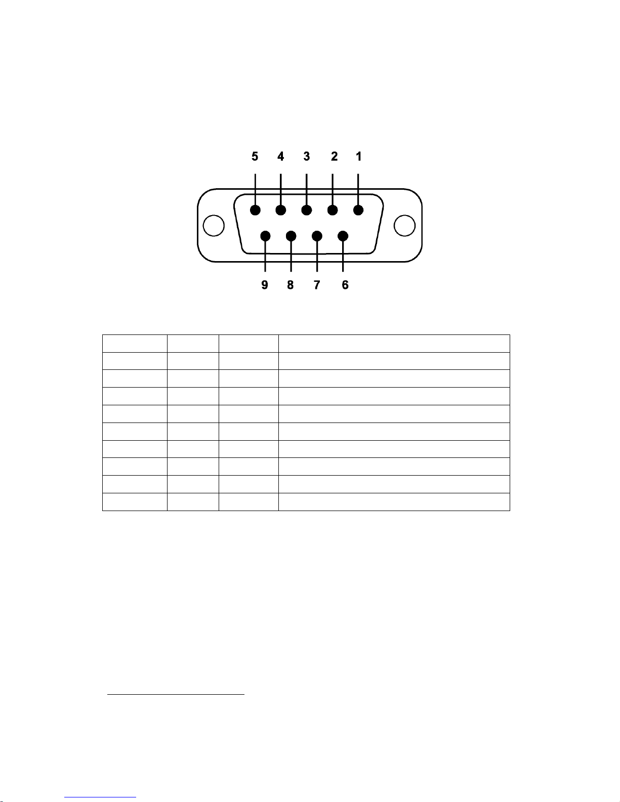
2.2. RS-232 Interface
2.2.1. Pin-out
2.2.2. Signals
Pin Number Signal Direction Description
1 DCD Output Data Carrier Detect
2 TxD Output Transmitted Data
3 RxD Input Received Data
4 DSR N/A (Input) Option: Data Set Ready1
5 GND N/A Signal Ground
6 DTR Output Data Terminal Ready
7 CTS Input Clear to Send
8 RTS Output Request to Send
9 Vcc Input Power Supply
2.3. Factory Settings
The following is the factory settings of COM port. You can change the factory settings of COM
port with commands. In this case, you have to remember the changed factory settings.
Baud rate: 9600 bps
Data Bit: 8 bit
Parity Bit: No parity
Stop Bit: 1 stop bit
Flow control: None
1The default hardware configuration is for using CTS. If you want to use DSR, please contact
us.

6
2.4. Status LED
There are two LED on HPS-120.
OPR (Red): When HPS-120 is supplied the power, it is turned on or flashed.
LNK (Green): When a wireless link is on, it is turned on. If HPS-120 is in the
configuration mode, it will be flashing every second.
2.5. Reset Button
The RST button has the following functions.
Enter / Exit the configuration mode
Restore the factory settings1
Disconnect and reconnect a wireless connection.
2.5.1. Entering the Configuration Mode
When the LNK LED is OFF, push the RST button. When the LNK LED is ON, you have to push
the RST button twice to enter the configuration mode. If you enter the configuration mode
successfully, LNK LED will be flashing every second. And HPS-120 COM port will be stored the
factory settings.
2.5.2. Exiting the Configuration Mode
You can have two options to exit the configuration mode.
Exit the configuration mode by software: Type “X”.
Exit the configuration mode by the RST button: Push the RST button.
2.5.3. Re-connection
When the LNK LED is on, you can push the RST button to disconnect and reconnect a wireless
link.
1If you push the RST button, the COM port of HPS-120 will be stored the factory settings.

7
3. Hardware Installation
3.1. Hardware Description
3.2. Power Supply
You can supply power to the HPS-120 as follows:
Use an AC/DC converter (Output Power: +5 ~ +12Vdc / 300mA).
Use a provided USB cable.
You can supply power via 9th pin of D_SUB 9 Pin connector.
3.3. Install Procedure
Step 1: Assemble a provided antenna to HPS-120 body.
Step 2: Plug a HPS-120 into the COM port of device.
Step 3: Power on.
Step 4: Configure the HPS-120, if necessary.
Antenna /
Connector
DC In Jack
Screw
RS-232
Connector
RST Button
OPR LED
LNK LED
USB Cable
for Power

8
4. Usage
You can change the configuration of HPS-120 using Hyper Terminal1
4.1. Hyper Terminal Settings
.
Baud Rate: 9600 bps / Data Bit: 8 / Parity Bit: None / Stop Bit: 1 / Flow Control: None /
Emulation: VT100
4.2. Configuration
4.2.1. Starting Configuration
Step 1: Plug a HPS-120 into a COM port of PC. And Power it on.
Step 2: Open a Hyper Terminal and set it up.
Step 3: Push the RST button on HPS-120. If you enter the configuration mode successfully, LNK
LED will be flashing every second.
Step 4: Hit the <Enter> key, 5 second later.
Step 5: Change the configuration of HPS-120 with commands, if necessary.
4.2.2. Usage Printing
If you are in the configuration mode, type “?<Enter>” for listing of commands. If you want to
know the usage of a command, type “?[command]<Enter>”. All commands and parameters are
case sensitive. And you cannot use a <Backspace>.
4.2.3. After Configuration
After finishing the configuration, you have to execute a command “X” to apply changes.
1This manual is required the software version 2.0 or above.

9
4.3. Command Set
The commands are as follows1
Item
:
Syntax Description Remarks
1. Connecting
address
AAddr<CR>
Set a remote device
address for a wireless
connection.
A local and remote
BD_ADDR always need to
be difference.
2. Baud rate BBR[D]<CR> Change the baud rate.
D (option): Change a
factory setting2
Baud Rate (BR) - 0: 1200,
1: 2400, 2: 4800, 3: 9600,
4: 19200, 5: 38400, 6:
57600, 7: 115200
.
3. COM port CCOMPort<CR> Change a request serial port.
COMPort: ‘1’ ~ ‘7’
Only valid in connection mode 2.
4. PIN code EPIN<CR> Authentication Off: hit <Enter>
Authentication On: Type up to 11
characters
Paired adapters should
have a same PIN code.
5. Flow control FFC[D]<CR> Set the Flow control.
D (option):
Change a
factory setting3
FC - 0: None
.
1: Hardware4
2: DTR/DSR
5
6. Search timer GTO<CR> Set a search timeout.
TO (timeout): ASCII ‘0’ ~ “999”
Connection mode 3 only.
Default: 10 sec.
7. Max number
of search
HNO<CR> Set the max number of search.
NO: ASCII ‘0’ ~ “999”
Connection mode 3 only.
Default: 10
8. Search device ITO,NO[L]<CR> Execute searching devices.
TO:ASCII ‘0’ ~ “999”
NO: ASCII ‘0’ ~ “999”
L (option): Display a long form.
Connection mode 3 only.
‘,’: ASCII 0x2C
9. Discovery
mode
JE/D<CR> Set the discovery mode.
‘E’: Enable
‘D’: Disable
Connection mode 1 only.
Default: Enable
10. Low Power
Mode
KE/D<CR> Set the low power mode.
‘E’: Enable
‘D’: Disable
Default: Disable
1If you push the RST button, the COM port of HPS-120 will be stored the factory settings.
2If you change a factory setting for baud rate, you have to remember it.
3If you change a factory setting for flow control, you have to remember it.
4This is a flow control between HPS-120 and DTE (will not be passed it over the air).
5This is a flow control between DTE (will be passed it over the air).

10
11. Connection
mode
MMode<CR>1Set a connection mode.
Mode: ‘0’ – ‘3’
Mo
de 0 & 2: Required a
remote address.
Mode 2: Required a serial
port.
0: 1:1 Mode
1: WAIT Mode
2: REGISTER and
CONNECT Mode
3: WAIT Command Mode
12. Friendly
name
NName<CR> Set a friendly name up to
11 characters.
13. Parity Bit PPA[D]2Set the parity bit.
<CR>
D (option): Change a
factory setting3
0: None, 1: Odd 2: Even
.
14. Connection
Timeout
QTO<CR> Set the connection timeout.
TO: ASCII ‘0’ ~ “999”
Connection mode 3 only.
Default: 10 sec.
15. Stop Bit SST[D]<CR> Set the stop bit.
D (option): Change a
factory setting4
0: 1 Stop, 1: 2 Stop
.
16. Connect TAddr[,TO]<CR> Try to make a connection.
Addr: a remote address
TO (option): ASCII ‘0’ ~ “999”
Connection mode 3 only.
‘,’: ASCII 0x2C
Default Timeout: 10 sec.
17. Cancel UCancel a command. Connection mode 3 only.
18. View V
Display the device
information
You can find out a software
version.
19. CoD WCoD<CR> Set the class of device.
CoD: 6-Hex in ASCII
Default: “001F00”
20. Exit XApply changes. Rebooting
21. Status Z Display the status of state
machine.
‘S’: Idle / ’P’: Pairing /
’C’: Connecting /
’A’: RF on / ’I’: Inquiring
22. Usage ?[C]<CR>
Display the command list
or usage.
C: Command
1<CR>: Carriage Return (0x0D)
2[]: An optional parameter.
3If you change a factory setting for parity bit, you have to remember it.
4If you change a factory setting for stop bit, you have to remember it.
Other manuals for HandyPort-Serial HPS-120
2
Table of contents


