JTS CS-120 Series User manual

Digital Conference System
59508-068-06
CS-120 Series

Digital Conference System Product Manual
CS-120 Series


A.Product Functions and Features 1
B.External Functions 3
2-1 Control Unit 3
2-1-1 Front Panel 4
2-1-2 Back Panel 5
2-2 Extension Unit 7
2-3
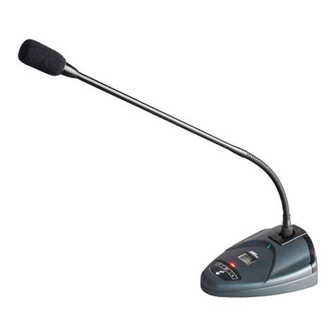
CS-120CH Chairman Unit / CS-120DU Delegate Unit
8
2-4 Pluggable Gooseneck Microphone 10
C.System Connection 11
3-1 Conference Unit Connection 11
3-2
Connection of Extension Unit (EXU) and Control Unit (CU)
13
3-3 Peripheral Equipment Connection 14
3-4 Video Tracking Equipment Connection 15
D.System Set-up and Operation 16
4-1 Initialization and Self-examination 16
4-2 System Self-examination 17
4-3 Main Directory 18
4-3-1 Network Address 19
4-3-2 Unit Number 19
4-3-3 Unit Settings 21
4-3-4 Video Settings 25
Contents

4-3-5 Language Settings 27
4-3-6
Unit Test (Cannot Access under “Voice” Mode)
27
4-3-7 Record Settings 31
4-3-8 CU Information 33
E.Instructions 34
5-1 Unit Number 34
5-2 Speak 35
5-3 Vote 37
5-4 Volume Control 37
5-5 LCD Display of Conference Unit 37
5-6 Exclusive Functions of Chairman Unit 38
F.Equipment Installation 41
6-1 Extension Unit (EXU) and Control Unit (CU) 41
6-2 Conference Unit 41
6-3
Electric Cable Connection, 7PIN Plug and Outlet
42
6-4 43
6-5 Other Accessories 44
G.Operating Environment and Maintenance 46
H.Technical Specifications 48
8-1 System Specifications 48
8-2 Control Unit (CU) 49
8-3 Conference Unit 50
Audio Connection of CS-120 Conference System

1
4-3-5 Language Settings 27
4-3-6
Unit Test (Cannot Access under “Voice” Mode)
27
4-3-7 Record Settings 31
4-3-8 CU Information 33
E.Instructions 34
5-1 Unit Number 34
5-2 Speak 35
5-3 Vote 37
5-4 Volume Control 37
5-5 LCD Display of Conference Unit 37
5-6 Exclusive Functions of Chairman Unit 38
F.Equipment Installation 41
6-1 Extension Unit (EXU) and Control Unit (CU) 41
6-2 Conference Unit 41
6-3
Electric Cable Connection, 7PIN Plug and Outlet
42
6-4 43
6-5 Other Accessories 44
G.Operating Environment and Maintenance 46
H.Technical Specifications 48
8-1 System Specifications 48
8-2 Control Unit (CU) 49
8-3 Conference Unit 50
A.Product Functions and Features
1-1
The Number of Active Microphones and Operation Modes
● The limit of active microphones (1/2/4) and of speaking time
● Four operation modes set up through control unit:
“Open” mode: When reaching the maximum number of active microphones,
press the microphone button (TALK) to register a speaking
(enter speaking condition automatically in order).
“Override” mode: When reaching the maximum number of active
microphones, press the microphone button to control and override
(turn o) active microphones (override the active microphones in order).
“Voice” mode: Auto voice control mode. The user can set up the
sensitivity of activating the microphones.
“Apply” mode: A delegate can press speaking button to apply for a
speaking, and after the chairman approves the application, the delegate
can speak.
● In “Open/Override/Apply” mode, the chairman unit can be
set in “podium mode”, keeping in active state.
1-2 Vote/Ballot Function
●
If the chairman unit is equipped with a graphical LCD, it can conduct a
ballot which follows the regulations of Parliament (approve/oppose/
abstain), or a questionnaire (1, 2, 3, 4 and 5). The result can be
displayed on LCD of all conference units (the beginning and the end of
the vote are controlled by the chairman unit).
1-3 Information Display
● The directory and information in multiple languages (Simplified Chinese,
Traditional Chinese and English) can be displayed on 256*64 graphical
LCD of conference units.
1-4 Auto Video Tracking
● Auto video tracking function can track the speaking delegates in the
conference.
1-5
System Self-examination
●
Built-in self-examination function can perform self-examinations for
the microphone, button, speaker and LED light of every unit.

CS-120 Conference System Product Manual
2
DELEGATES / CHAIRMAN
1-6 Against Radio Frequency Interference of Cell Phones
1-7 Extend and Connect Between Control Units Easily
●
A control unit (CU) plus extension unit (EXU) system can control a
maximum of 254 conference units.
1-8 Desktop or Embedded Conference Units Can Increase
The Users’ Convenience and Fulfill The Aesthetic
Requirement. The Users Can Choose The Installation
Method to Reach Their Diverse Requirements.
CS-120CU
CS-120 EXU
D7120-XX
7P extension cord
Connect with a
maximum of 90
conference units
with LCD
Each route can connect with 30
conference units with LCD
CAT.5 network cable
with RT-45 plug
PC
Router/Hub

3
B.External Functions
2-1 Control Unit (CU)
CU is the core of the whole conference system. It provides electric power for all
conference units and connects hardware with software. CU can operate basic
conference management without personal computer in independent operation
mode. A CU can connect with 90 conference units (with LCD).
When a system needs more conference units:
●Add extension unit (EXU). An EXU can provide electric power for 90
conference units. A CU plus many EXUs system can control a maximum of
254 conference units.
13
245789 6
10 2314161819
20
22 21 15
13 241217 11

CS-120 Conference System Product Manual
4
1
2
3
4
5
6
7
2-1-1 Front Panel
Power switch
Main screen button: Press the button for 3 seconds, and enter the directory of CU
LCD; after entering the main screen, press the software button of each function as
the display shows to enter subdirectory; operate and set up.
320*240 LCD: Display CU’s state and directory.
Line in volume: Adjust Line input signal on back panel.
The maximum number of active microphones knob (1/2/4): Set the number of
speaking delegate units in conference.
Operation mode (Open/Override/Voice/Apply): Set the mode of speaking order
in conference. The following is function of each mode:
“Open” mode: When reaching the maximum number of active microphones (ac-
cording to the number of speaking units set by (5)), the function of speak button is
to register a speaking in order. A maximum of 6 microphones can wait in line for
speaking. The gooseneck light of pending microphones will icker, but the users
cannot speak. When one active microphone is turned o, a pending microphone
will be on automatically in order.
“Override” mode: If reaching the maximum number of delegate units (according to
the number of speaking units set by (5)), the rst active microphone will be turned
o automatically when the speak button of another microphone is pressed, and
the last delegate unit whose button is pressed can speak. The system will limit the
number of active microphones within the range set by (5).
“Voice” mode: The users do not need to press speak button but use voice to
activate the microphones. When the user speaks close to the microphone, the
microphone will be activated automatically. If the user stops talking for 5 seconds,
the microphone will be turned o automatically. The sensitivity can be set as high/
medium/low through unit settings of CU.
“Apply” mode: Press speak button of a delegate unit to apply for speaking instead
of speaking immediately. When the chairman approves the application, the micro-
phone of the delegate unit will be activated; if the chairman rejects the application,
the application will be cancelled and the microphone will not be activated.
Master volume: Regulate the speaker volume of all conference units.
Record: Press this button to record the conference.
SD card slot: The storage device of the recordings. When recording a confer-
ence, you need to insert formatted SD card (FAT format). The maximum stor-
age capacity of SD card supported by the product is 32 GB.
8
9

5
2-1-2 Back Panel
CH0 line output: 3-pin XLR balanced output which can transmit the voice in
conference to other devices in a long distance.
Video input (4 BNC adaptors): There are 4 video inputs and 1 output. Con-
nect with dome cameras for video tracking in conference, or link other analog
signals to display videos.
Video output (1 BNC adaptor): There are 4 video inputs and 1 output. Export
analog signals to TV wall or projector for video display.
Power plug: AC110V or AC220V input.
Alarm audio input terminal (φ6.3mm jack unbalanced input): Connect to audio
output of alarm system to deliver broadcasting alarm message to every confer-
ence unit. The message will also be broadcasted by speakers of conference
units to inform emergency conditions.
Fire alarm triggering input terminal:
Trigger the alarm: When the alarm triggering input terminal contacts with ground
terminal (short circuit), all microphones of conference units will be turned o (in-
cluding speaking ones and pending ones), and the gooseneck lights will be icker-
ing. All conference units deliver alert sound once, and the
speakers of conference
units start to broadcast the message delivered by (14) until the alarm stops.
Stop the alarm: When the alarm triggering input terminal does not contact with
ground terminal or input high electrical potential (<+5VDC), conference units will
return to normal condition.
Line input adaptor (φ6.3mm jack balanced input): Connect external audio with
conference audio for remix.
Record input terminal (one RCA): Connect external audio with internal
recordings for remix, and the recordings are stored in SD card.
Record output terminal (one RCA): Export recordings. The user can supervise if
the recordings are normal, or can export the recordings to other devices.
CH0 line output: RCA terminal with balanced output signal. Export conference
audio to other devices or equipment.
Unit connection output terminal (1-3, three output terminals, 7P-DIN plug): Connect with
conference units, such as chairman unit/delegate unit; or connect with EXU to increase
the number of conference units. Every output terminal can connect with a maximum of
30 conference units with LCD (without extension cords).
Extension slot: For loop connection (φ6.3mm connector IN/OUT).
Ethernet connector: Connect with CU and PC with TCP/IP protocols, for example,
location settings of dome cameras for video tracking.
10
11
12
13
14
15
18
16
17
19
22
20
21

CS-120 Conference System Product Manual
6
Slow Control input terminal: Usually connect to Slow Control output terminal of
translation system (such as IT-12M or IT-12M4).
Instructions: When the conference system connects to translation system for
simultaneous translation, if the translator cannot follow the speed of the speaker,
the translator can press SLOW button on translation unit. When the CU receives
the SLOW signal, the speaking unit will deliver alert sound (when the alert sound
is turned on) and the gooseneck light will turn o (about 1 second) to remind the
speaker to slow down.
Camera control interface (RS-485): Control line to connect with dome cameras.
When connecting with a dome camera, TX+ of CU links to RX+ of the camera, and
TX- of CU links to RX- of the camera.
24
23

7
1
2
3
4
5
Power switch and power indicator (red light): When press power button (ON), the
machine has built-in ON/OFF interlocking function connecting to CU.
Extension input terminal (7P-DIN): Connect with CU or the former EXU for
signal input of extensive conference units in the system.
Extension output terminal (7P-DIN): If one EXU is not enough for the number of conference
units, you need to connect with another EXU. Connect the output terminal of this EXU with
the input terminal of next EXU to increase signal input of conference units.
Unit connection terminal 7P-DIN (1-3, three output terminals): Connect with conference
units, such as chairman unit/delegate unit. Every output terminal can connect with a maxi-
mum of 30 conference units with LCD (without extension cords).
Power adaptor
2-2 Extension Unit (EXU)
DELEGATES / CHAIRMAN
1
245 3

CS-120 Conference System Product Manual
8
2-3 CS-120CH Chairman Unit / CS-120DU Delegate Unit
VOLUME
MIC.
5
1234
CS-120CH
Digital Conference System / ChairmanUnit
1
8
2
12 11
3
5
910
67
4 5
1
2
Headphone volume control: The volume increases 1 dB when pressing the
upper button; the volume decreases 1 dB when pressing the lower button.
Multi-function buttons and indicators (5 buttons): In dierent modes, when the
indicator ickers, press the correspondent button to operate (the functions are
showed in the table below):
1 2 3 4 5
Regular
operation
Vote
(chairman unit) -Number of
speaking -
Language
Vote Ballot
(chairman unit) -Questionnaire
(chairman unit) - -
Register Register
attendance - - - -
Ballot - Approve Oppose Abstain Enter
Questionnaire 1 2 3 4 5
Function
Button No.

9
3
4
Priority button (only equipped on chairman unit): The user can set priority mode
in CU. The following is the functions:
“All mute”: When the chairman presses the priority button, all active microphones
of delegate units will become mute temporarily; when the chairman releases the
priority button, all microphones return to former state.
“All o”: When the chairman presses the priority button, all active microphones
of delegate units will be turned o, and the applications of applying (apply
mode) or pending (open mode) delegate units will also be cancelled.
If the microphone of chairman unit is not activated, press the priority button
can also activate the microphone.
When alert sound is set as “ON”, press the priority button will produce alert
sound.
Speak button (chairman unit): Turn on/o the microphone and speaking indica-
tor.
Speak/speak application button (delegate unit): Dierent functions in dierent
modes, as the following shows:
“Override” mode: Press the button to turn on/o the microphone and indicator
(speaking indicator and gooseneck light).
“Open” mode: When the number of active microphones does not reach
the maximum, press the button can turn on/o the microphone. When the
microphone is on, the speaking indicator and microphone light ring (gooseneck
light) will become red. When the number of active microphones reaches
the maximum, press this button can apply/cancel speaking application. The
speaking indicator and the gooseneck light will become red and ickering. A
maximum of 6 delegate units can enter speaking application waiting line.
“Voice” mode: When the user is not talking, the speaking indicator (speaking
light) of microphone is red light; when the user is talking, the speaking indicator
(speaking light) and the light ring (gooseneck light) of the microphone are
red. When the microphone is on, the user can press the button to turn o the
microphone.
“Apply” mode: When the number of active microphones does not reach
the maximum limit, press the button to apply/cancel a speaking application.
Only one delegate unit can apply in the same time. When the number of
active microphones reaches the maximum limit, only one delegate unit can
enter speaking application line, but the application message will show on the
chairman unit after any active microphone is turned o. And then the chairman
will decide to approve or reject the application.
Speaking indicator (speaking light) (red). The following is its conditions:
When the microphone is on, the indicator is red.
In “Apply” mode, the indicator is ickering.
In “Voice” mode, the indicator is on.
When the priority button of chairman unit is pressed, the indicator is red.
4
5

CS-120 Conference System Product Manual
10
Built-in Hi-Fi speaker: To export the speaking sound in conference. The master
volume setting in CU controls the volume of the speaker. When the micro-
phone is on or the user inserts the headphone, the speaker becomes mute to
avoid whistles.
256*64 high brightness graphic LCD: Display directory and messages, and
change languages (such as Traditional Chinese and English).
Gooseneck microphone adaptor
Microphone adaptor (φ3.5mm): Connect to external microphone output. When the
user inserts a microphone, (8) gooseneck microphone will be o.
Headphone adaptor (φ3.5mm): Connect to external headphone output. When
the user inserts headphones, (6) built-in speaker will be o.
0.6m 7P-DIN standard plug cable (female connector*1): Connect to the next
conference unit or terminal connector.
1.5m 7P-DIN cable standard plug (male connector*1): Connect to the former
conference unit, CU or output terminal of EXU.
6
7
8
9
10
11
12
2-4 Pluggable Gooseneck Microphone
1
2
Cardioid condenser microphone
Microphone on/o LED light ring
When the microphone is on , the LED light ring will keep on
When the user applies for speaking, the LED light ring will be ickering.
The user can freely adjust the angle and the direction of the gooseneck micro-
phone.
Adaptor with screw thread. During an adjournment, the gooseneck microphone
can be removed for storage.
3
4
12 3 4

11
C.System Connection
3-1 Conference Unit Connection
CS-120 Conference System has simple and eective structure. The system
can be installed easily and fast without special training. Special extension
cords connect the conference units with other conference units and CU by
daisy chain scheme. CS-120CU has 3 export backbone cables (7P-DIN)
to connect with conference units. Every conference unit is equipped with a
cable with 7P-DIN male connector. Since the distance between conference
units are diverse, there are original cable connection and extension cable
connection as follows:
The distance between CU and the rst
conference unit
(the length of extension cable)
The number of connectable conference
units of every connector
10m 30
20m 27
40m 24
80m 21
100m 16
Table 3-1 the relationship between extension cable length and conference units
When extension cable connects CU with the rst conference unit, in the
meantime, the maximum load current of CU can aect all following units.
However, the eect of extension cable between the last two conference
units is negligible, because the cable only carries the current of the last unit.
For example, in one way without other extension cable, only one 100 m
extension cable connects the 29th with the 30th conference unit.
● Original cable connection
CS-120 conference units are equipped with a 1.5 m 7-Pin cable with male
connector and a 0.6 m 7-Pin cable with female connector. The male cable
connector of the rst conference unit links to the 7 PIN-DIN output adaptor.
The female cable connector behind the rst conference unit links to the male
connector of the second conference unit, and so on. The female connector of the
last conference unit links to the terminal connector.
● Extension cable connection
When the distance between conference unit and CU or other conference units
is longer than 2.1 m, the user needs to use extension cable to connect the units.
Because of the resistance, the extension cable causes the decrease of voltage.
When the cable length is longer, the number of connectable devices of every
cable connector will decrease.
The relationship is as the following table:

CS-120 Conference System Product Manual
12
For instance:
Originally, if the number of conference units is less than 90 without extension cable,
CS-120CU has 3 7P-DIN adaptors: every adaptor can connect with a maximum of 30
conference units with LCD, and a CU can connect with 90 conference units. However, if
the distance between conference units and CU is about 100 m, according the previous
table, every 7P-DIN adaptor can only connect with 16 conference units with LCD, and a
CU can only connect with 48 conference units.
Connect buckle
Connect with CU Connect with the next
conference unit
or
Connect with terminal
connector if it is the last
conference unit
CS-120DUCS-120DU
D7120-XX extension cord
Connect with the next conference unit
The number of
connectable
conference
units according
to the length of
extension cord
(Table 3-1)
CS-120CU
CS-120DU

13
DELEGATES / CHAIRMAN
3-2 Connection of Extension Unit (EXU) and Control Unit (CU)
CU is the core of the whole conference system. CU provides power for
all conference units. As a result, the number of units connecting with CU
is associated with CU’s ability to provide and control power. When there
are more conference units, or most conference units need long-distance
connection, CU needs to connect with EXU to increase the number of
conference units in the system. An EXU can provide power for 90 conference
units (with LCD). A CU and many EXUs can control a maximum of 254
conference units.
For longer distance between conference units and CU/EXU. One end of
the cable is equipped with 7P-DIN male connector, and the other end is
equipped with 7P-DIN female connector. Connect the female connector with
conference units, and connect the male connector with CU output. Adopting
extension cable will decrease the number of connectable conference units.
The number of connectable conference units of every 7P-DIN adaptor is
showed in Table 3-1.
CS-120CU
CS-120EXU
D7120-XX
7-pin extension cord
D7120-XX
7-pin extension cord
CU connects with PC through a
router or hub
Each output terminal can connect with a maximum of 30 conference units
with LCDs
Network cable with RJ-45 plug
PC
Router
Connect with a
maximum of 90
conference units
with LCDs

CS-120 Conference System Product Manual
14
3-3 Peripheral Equipment Connection
CS-120CU has many peripheral equipment adaptors. Audio signal input/
output terminals can connect with dierent peripheral equipment, as the
following gure shows.
CS-120CU
CH0 balanced linear output
terminal which can connect with
PA system or mixing console
Symmetrical
Signal line out
positive/negative
Recording
signal output
which can
connect with
PA system or
mixing console
Fire alarm
audio input
Fire alarm
triggering
contact
Linear signal input. Use “LINE IN VOL” knob on
front panel to control signal value
SLOW control input
which connects with
SLOW control output
of IT-12M translation
system
Recording signal input

15
3-4 Video Tracking Equipment Connection
CS-120CU has 4 input and 1 output video switching interface. By using
conference planning and video tracking software for CS-120, the user can
conduct preset tracking and locating for every conference unit. After setting
up the locating, when the user starts to speak with desktop machine, the
dome camera will quickly track the location of the speaking conference unit
according to the preset locating, and project the speaker’s image on the
screen in the conference by the video switching interface of CU. Please read
the product manual of “video tracking” software for more details.
The following gure is the schematic diagram of video tracking connection:
CAT-5 network cable and
RJ-45 plug
CAT-5
network
cable
RJ-45 plug
Connect with
projector or
screen
DIN 7P male-female
extension cord
RS-485
Connect with
conference units.
Connect with 30 units
without extension
cord. Look Table 3-1
for the number of
connectable units
in each route with
extension cord.
CS-120CU
Dome
cameras
RS-485
Router
PC
Other video output
This manual suits for next models
3
Table of contents
Other JTS Conference System manuals