HANLI HL-1000 Series User manual

1
User's Manual of Fiber Laser Chiller
HL-1000/1500/2000/3000/4000/6000/8000/12000/15000/20000/30000/40000/50000 Series
SCH-/1500/2000/3000 Series
SCL-/1500/2000/3000 Series
SCHYTJ-/1500/2000/3000 Series
SY-1500/2000 Series
User’s Manual of Fiber Laser Chiller
WUHAN HANLI REFRIGERATION TECHNOLOGY CO., LTD.
Add: No. 1, Second Road, XinFuYua, Hannan District, Wuhan, China
Post Code: 430090 Email: hanli-laserchiller@hanlizl.com
Tel: +86-13682641130 ,
www.hanlichiller.com

User's Manual of Fiber Laser Chiller
2
Content
foreword ----------------------------------------------------------------------------------------------- 4
Warning notices -----------------------------------------------------------------------------------------5
1Overview ---------------------------------------------------------------------------------------------8
2Conditions of use ------------------------------------------------------------------------------------8
2.1 Environmental requirements -------------------------------------------------------------- 8
2.2 Medium requirements ---------------------------------------------------------------------- 9
3Model description ---------------------------------------------------------------------------------- 10
4Model description ---------------------------------------------------------------------------------- 10
5Appearance and part name ------------------------------------------------------------------------ 12
6Installation ------------------------------------------------------------------------------------------12
6.1 Installation conditions and requirements ---------------------------------------------- 12
6.2 Waterway connection---------------------------------------------------------------------14
6.3 Circuit connection -------------------------------------------------------------------------14
6.4 Add water and exhaust -------------------------------------------------------------------15
6.4.1 Add water -------------------------------------------------------------------------15
6.4.2 Exhaust and drainage ------------------------------------------------------------- 15
6.5 Warm Tips --------------------------------------------------------------------------------- 16
7Product use-------------------------------------------------------------------------------------------16
7.1 Inspection before commissioning ------------------------------------------------------- 16
7.2 Introduction to controller panel --------------------------------------------------------- 16
7.2.1 Introduction to Hanli split controller panel ------------------------------------ 16
7.2.2 Introduction to Jingchuang split controller panel --------------------------- 17
7.2.3 Introduction to LCD controller panel ---------------------------------------- 18
7.3 Power on display ----------------------------------------------------------------------------18
7.4 Temperature display ---------------------------------------------------------------------- 19
7.4.1 temperature display of integrated controller------------------------------------19
7.4.2 temperature display of split controller ---------------------------------------- 19
7.5 Parameter setting -------------------------------------------------------------------------- 19
7.5.1 parameter setting of split controller -------------------------------------------- 19
7.5.2 parameter setting of LCD controller-------------------------------------------- 20

User's Manual of Fiber Laser Chiller
3
8Maintenance ---------------------------------------------------------------------------------------- 20
8.1 Dustproof in summer --------------------------------------------------------------------- 20
8.2 Anti-freeze in winter ---------------------------------------------------------------------- 21
8.3 Routine maintenance ----------------------------------------------------------------------22
9Fault analysis and troubleshooting --------------------------------------------------------------- 23
10 Circuit diagram ----------------------------------------------------------------------------------- 25
11 Transportation and storage ---------------------------------------------------------------------- 27
11.1 Transport requirements ----------------------------------------------------------------- 27
11.2 Storage requirements -------------------------------------------------------------------- 27
12 Other instructions ---------------------------------------------------------------------------------27
12.1 Service support ---------------------------------------------------------------------------27
12.1.1 Warranty scope ---------------------------------------------------------------- 27
12.1.2 Circumstances beyond the scope of warranty ----------------------------- 27
12.2 Other matters ----------------------------------------------------------------------------- 28

User's Manual of Fiber Laser Chiller
4
foreword
Thank you for your trust in our company and choosing to use our company's fiber
laser chiller. In order to enable you to better understand and use our company's products, to
make them play the best effect, and to provide you with perfect after-sales service, we
sincerely welcome you to Read this manual carefully before use, and consult this manual if
you have any doubts during the use of the product.
This manual is prepared for the owners and users of the chiller. It includes product
performance parameters, appearance and component names, working principle, daily
maintenance, fault description and troubleshooting methods, etc., and is used for
installation, operation, commissioning and maintenance.
This manual is not a quality assurance document, and the printing corrections,
revisions of product information, and product improvements are the final interpretation of
the company without prior notice, and the updated content will be compiled into the
reprinted manual. If you have any questions about the use of the product or suggestions for
improvement, please contact our service personnel
Warning notices
In order to ensure your personal safety and avoid property damage, you must pay
attention to the warning notices in the company's manual. The warning is based on the
risk level from highest to lowest and is listed below, but not limited to the following.
General knowledge of electricity use and safety regulations should also be followed.
Dangerous
Be sure to take safety measures, otherwise it will lead to death or serious
personal injury.
Warning tips
Warning signs
Operational specifications
Please be operated
by technical
personnel with
professional
Handling, installation of piping, electrical, operation,
maintenance, maintenance and other operations, must be
carried out by personnel with professional knowledge.

User's Manual of Fiber Laser Chiller
5
knowledge
Must be implemented
High Voltage Risk
Contact with live parts can result in serious personal injury or
death.
scald burn risk
Any part of the body and heat resistant articles must be kept
away from this high temperature area, otherwise it will cause
personal injury or property loss.
Electrical connections
Must be implemented
A) The power supply mode must be selected in accordance with
the relevant contents of the nameplate or the manual;
B) The cable must use standard cable, and the wire diameter
shall be selected according to the standard;
C) Grounding must be installed and the connection must
be reliable, otherwise it will cause the danger of electric
shock or fire.
Maintenance
Must be implemented
It must be cut off for 3 minutes before it can work.
Scrap
Must be implemented
When the equipment has reached its service life and needs to
be scrapped, it must be disposed of with industrial garbage.
Please ask professional guidance for scrapping.
Do not use beyond
specification
Prohibited
It is forbidden to use the equipment beyond the specification in
order to avoid major accidents such as equipment damage,
injury, fire and electric shock.
Cannot be used in
an explosive
environment
Prohibited
Do not install in a dangerous place where there is combustible
gas.
Do not run the
device without an
outer cover
Prohibited
There are live parts in the machine. Do not run without an
outer cover
Danger of electric shock.
Waterproof
Prohibited
Do not let the equipment drench or soak, otherwise there
may be short circuit and electric shock hazard.
Warning Be sure to take safety measures, otherwise it may lead to death or serious personal injury.

User's Manual of Fiber Laser Chiller
6
Warning tips
Warning signs
Operational specifications
Transport, installation
Must be
implemented
When the equipment is transported and installed, the
equipment must be fixed firmly, otherwise there is a risk of
overturning and falling.
Electrical protection
Must be
implemented
Power cable access terminal must match the leakage and
overload protection device according to the rated current
indicated on the equipment nameplate.
Discontinue operation
immediately when abnormal
occurs
Must be
implemented
When the equipment is abnormal, as long as the cause is not
clear, it is forbidden to start, otherwise there will be
damage, electric shock, fire, injury risk.
Do not extend fingers and
foreign objects into the gap of
the equipment
Prohibited
The equipment is equipped with rotating parts. When the
equipment is running, it is forbidden to put fingers or
foreign bodies into the gap of the equipment, otherwise it
will cause personal injury.
Refrigerant leakage
Must be
implemented
a) When refrigerant leakage occurs, please be sure to get
some air and ventilation. Otherwise a large amount of
refrigerant filled with closed space, will produce anesthesia
to the human body and cause asphyxiation risk;
b) Avoid contact with the skin, otherwise it will frostbite.
Notice
Please take safety measures, otherwise it may lead to minor personal injury and property loss.
Prompt item
Warning signs
Operational specifications
Prohibition of liquid transport
Prohibited
The equipment is forbidden to carry liquid to prevent internal
pipeline leakage.
Handling
Must be
implemented
a) Equipment should be fixed before handling to prevent
equipment movement caused by vibration and external force.
If there is excessive vibration and external forces, the internal
equipment is at risk of damage;
b) Keep the tilt angle ≤45°, otherwise the refrigeration
system will fail.
Operating environment
Prohibited
a) Prohibit the use of high temperature, humidity, strong
electromagnetic interference and other special environments;
b) Equipment must be installed in places without direct
sunlight and away from fire sources.
Installation
a) Equipment must be installed horizontally, otherwise the
refrigeration system will fail;
b) Items are prohibited within 1.5 meters around the suction

User's Manual of Fiber Laser Chiller
7
Must be
implemented
port and 2.0 meters around the outlet. If suction and exhaust
are obstructed, the cooling capacity of the equipment cannot
be used.
Before trial operation
Must be
implemented
a) Need to ensure that the equipment side water supply pipe
is not obstructed;
b)Need to check the water pipe and pump, confirm that there
is a proper amount of water into the pump, and the exhaust is
through the pump exhaust valve, otherwise it will cause
damage to the pump;
c) Confirm the condition of the equipment is normal and
safe, otherwise there may be injury and breakage.
Equipment no stampede
Prohibited
Please don't step on the equipment or sit on it, otherwise it
will cause the injury accident of falling.
Regular cleaning of air filters
Must be
implemented
Clean the air filter at least once a week. If the air filter is
obstructed, the refrigeration capacity will be reduced, the
power consumption will increase, and even the alarm will not
work properly.
Keep surface clean
Must be
implemented
a) Use non-corrosive cleaning agents for metals and plastics;
b) After cleaning, please take good care of the cleaning agent
to prevent liquid leakage anywhere in the equipment;
c) Containers that store detergents should be completely
sealed to avoid danger.
Wear protective gloves for
maintenance, repair and cleaning
Must be
implemented
a) The sharp edge of the condenser fin is dangerous to cut the
skin;
b) Internal compressor and refrigerant pipe temperature is
very high, direct contact with the skin has the risk of
scalding.
Anti-freezing
Must be
implemented
If the ambient temperature is lower than 0℃ and the
shutdown is long, the liquid should be discharged. Moreover,
use compressed air to clean the water in the system,
otherwise there is a risk of frostbite components and pipes.

User's Manual of Fiber Laser Chiller
8
1overview
This product is a cooling device designed and manufactured for laser cutting, laser welding,
laser engraving, laser marking, laser printing, etc. Coolant, to cool down the fiber laser, the other is
normal temperature coolant,Cool down the fiber laser cutting head.
The chiller is composed of a compressor, a condenser, a throttling device, an evaporator, a
water tank and a water pump, etc.
Its working principle is that the compressor compresses the superheated steam sucked from
the evaporator into a high-temperature and high-pressure gas, and discharges it to the condenser to
condense and release heat into a high-pressure liquid. The low-temperature and low-pressure super
cooled liquid is vaporized by the evaporator to absorb heat into superheated steam, and then
returns to the compressor to enter the next cycle to realize the refrigeration function. The heat
absorbed by the vaporization of the evaporator comes from the cooling medium, and the
temperature of the cooling medium will decrease. The low-temperature coolant is divided into two
by the water pump and pressed out. One path of low-temperature coolant cools down the laser, and
the other path is heated by a heating device to become a room-temperature coolant for the laser.
The cutting head cools down.

User's Manual of Fiber Laser Chiller
9
2 Conditions of use
2.1 Environmental requirements
Ambient temperature: 0 ~ 45℃;
Relative humidity: ≤90%;
Altitude: ≤3000m;
The relationship between the temperature of the cooling medium and the ambient
temperature is shown in Figure 2.
Ambient temperature℃
(a) Operating range of Pure Softened Water
Ambient temperature℃
(b) Operating range of anti-freeze water
FIG. 2 Operation range of equipment
Note: The above operating range is obtained in the laboratory according to the standard product
test, for reference, the operating range of each specific model may be slightly different, please
contact the manufacturer for details.
Medium temperature
Normal operating range
Medium temperature

User's Manual of Fiber Laser Chiller
10
2.2 Medium requirement
The cooling medium must be softened water, such as pure water, distilled water, high-purity water,
etc. It is allowed to add ethylene glycol with a volume ratio of ≤30%, or ethanol with a volume ratio
of ≤20%, and it is allowed to add preservatives and bactericides approved by the manufacturer.
It is strictly forbidden to use antifreeze with a volume ratio greater than 30%, oil and oil-based
liquids, flammable and explosive liquids, liquids with solid particles, and liquids corrosive to
aluminum and stainless steel are strictly prohibited.
3 Model description
For example, HL-3000-QG2 /2 represents a laser cutting machine with a matching laser power of
3000W, which adopts a stainless steel coil evaporator, waterways are equipped with water filters, and
double temperature and two channels of water supply.
For example, SCH-1500 represents a handheld welding chiller with a matching laser power of
1500W, which is equipped with a water filter by default, and double temperature and two channels of
water supply.
Note: This Model description is our company's standard product code description, does not list all
models, please confirm with our company before ordering of specific models. If there is change,
without notice.
4 Performance parameters
No.
Equipment
model
Power
supply
Power
(kW)
Coolants
Freon
injection
(kg)
Lift
(m)
Rate of flow
(m3/h)
Weight(kg)
Equipment size
(mm)
Water
volume
(L)
1
HL-1000-
QG2/2
220V
50Hz
2.7
R32
0.28
44
2
41
590×470×750
16
2
HL-1500-
QG2/2
220V
50Hz
2.8
R32
0.28
51
2
48
590×470×805
16
3
HL-2000-
QG2/2
220V
50Hz
3.0
R32
0.32
51
2
51
610×570×810
16
4
HL-3000-
QG2/2
220V
50Hz
3.8
R32
0.4
47.5
3
65
655×535×950
21
5
HL-4000-
QG2/2
380V
50Hz
8.5
R32
0.73
62
4
93
75 0×610×1070
42

User's Manual of Fiber Laser Chiller
11
6
HL-6000-
QG2/2
380V
50Hz
10
R32
0.8
62
4
102
75 0×610×1070
42
7
HL-8000-
QG2/2
380V
50Hz
19
R32
1.3
58.5
10
137
930×790×1250
70
8
HL-12000-
QG2/2
380V
50Hz
18
R410A
3.3
58.5
10
186
1170×787×
1495
90
9
HL-15000-
QG2/2
380V
50Hz
28
R410A
1.9*2
65
12
257
1540×730×
1120
115
10
HL-20000-
QG2/2
380V
50Hz
32
R410A
2.7*2
65
12
315
1700×765×
1135
140
11
HL-30000-
QG2/2
380V
50Hz
35
R410A
2.4*3
60
20
500
2250×1000×
1365
200
12
HL-40000-
QG2/2
380V
50Hz
44
R410A
2.35*4
86
20
710
1875×1480×
1600
310
13
HL-50000-
QG2/2
380V
50Hz
49
R410A
/
60
32
950
2225×1680×
2165
350
14
SCH-1500
220V
50Hz
2.1
R32
0.27
20.5
2
41
76 0×485×430
13
15
SCH-2000
220V
50Hz
2.5
R32
0.36
27.5
2
43
76 0×485×430
13
16
SCH-3000
220V
50Hz
3.9
R32
0.53
51
2
60
850×485×577
13
17
SCL-1500
220V
50Hz
2.1
R32
0.27
25
1
30
970×422×435
13
18
SCL-2000
220V
50Hz
2.5
R32
0.35
30
1.2
30
970×422×435
13
19
SCL-3000
220V
50Hz
3.9
R32
0.52
51
1.8
45
1060×522×500
13
20
SCHYTJ-
1500
220V
50Hz
2.4
R32
0.35
44
1.2
60
985×420×710
13
21
SCHYTJ-
2000
220V
50Hz
2.5
R32
0.33
44
1.2
60
985×420×710
13
22
SCHYTJ-
3000
220V
50Hz
3.9
R32
0.6
51
1.8
98
1110×530×
1060
13
23
SY-1500
220V
50Hz
2.4
R32
0.3
44
1.2
74
945×540×930
16
24
SY-2000
220V
50Hz
2.5
R32
0.3
44
1.2
76
945×540×930
16
Note: The above table is part of the standard product performance parameters, for reference only. If
there is change, without notice.

User's Manual of Fiber Laser Chiller
12
5 Appearance and part name
Note: the appearance and part name above are only one of the models. The appearance and part
name of different models may vary slightly.
6 Installation
6.1 Installation conditions and requirements
Open the package and check whether the equipment is in good condition and the attachment
list is complete.
It must be installed horizontally and cannot be tilted, as shown in FIG. 3. Anchor bolts
shall be used to fix casters-free equipment, and universal wheels shall be locked for
equipment with caster.
No shielding shall be allowed in the air inlet within the range of 1.5m and the air outlet
within the range of 2.0m, so as not to affect the heat dissipation of the equipment, as shown
in Figure 4.
Products shall not be installed in corrosive, inflammable gas, heavy dust, oil mist, metal and
other conductive dust, high temperature and humidity, strong magnetic field, direct sunlight
and other harsh environments, as shown in Figure 5.
Fan
Air switch
Controller
Air suction
(including filter
Wheel
Add water
Low temperature water outlet
Low temperature water inlet
Normal temperature water outlet
Normal temperature water inlet
Power cord outlet
Liquid level
Drain valve

User's Manual of Fiber Laser Chiller
13
FIG. 3 Requirements for equipment installation form
FIG. 4 Equipment installation space requirements
FIG. 5 Environmental requirements for equipment installation
Air
suction
Air
suction
Exhaust air
Direct sunlight

User's Manual of Fiber Laser Chiller
14
6.2 Waterway connection
Determine the piping layout direction according to the equipment import and export label,
in case the equipment cannot run normally.
The pipeline should be cleaned during internal construction to strictly avoid impurities.
Once impurities enter the system, it is easy to reduce the cooling capacity and may cause
faults of the water pump or refrigeration system.
Pipe connection: The connection method between the chiller and the laser is shown in FIG.
6. The inner diameter of the distribution pipe shall not be less than the diameter of the inlet
and outlet of the chiller.
Pipe resistance: The connection pipe between equipment should be the shortest distance,
avoid right Angle and bending, the total pressure drop ≤ 0.05mpa.
If metal lines are used, insulation measures should be taken to prevent energy loss.
Pipeline pressure must reach more than 1.5 times of water pump supply pressure.
Fig.6 Connection diagram of chiller and laser
6.3 Circuit connection
1. Please refer to the wiring label of the chiller when wiring.
2. Recommended reference standard for power cord diameter selection.
Rated current / A
≤5
≤10
≤15
≤25
≤35
≤50
Power line diameter
(copper wire)/mm2
1.0
1.5
2.5
4.0
6.0
10.0
This data is provided in accordance with IEC 60204-1, for reference only.
The power cord must use standard cable.
Rated power refer to chiller nameplate.
3.The main circuit of power supply must be installed with appropriate leakage and overload
protection devices, and ensure the chiller is well grounded.
4.The allowable fluctuation of power supply voltage is less than ±10% and frequency fluctuation is
less than ±1Hz, and it should be far away from the electromagnetic interference source.
5.Connection of signal terminals: output passive dry node signals for traffic alarm and over
temperature alarm.
Length of one side≤5m
Length of one side≤20m
Low temperature backwater
High temperature
backwater(External
Light Road)
Chiller
Laser
Cutting head
Switch
Note:
Water pipe color: for chillers, blue is effluent, red is backwater

User's Manual of Fiber Laser Chiller
15
6.4 Add water and exhaust air
6.4.1 Add water
Add softened water through the water inlet of the equipment to the standard liquid level area (green
area), as shown in Figure 7.
Figure 7 Liquid level identification
6.4.2 Exhaust and drainage
After the first addition of water and replacement of new water, exhaust the air in the pump to start the
use, otherwise it will damage the equipment. Exhaust method: slowly loosen the air-exhaust screw plug
of the pump (do not screw off), discharge air until water flows out, and then tighten the air-exhaust
screw plug (see Figure 8, in which only the exhaust positions of vertical pump and horizontal pump are
shown. According to customer requirements and specific type, the pump will be different, exhaust
location will also be different, and details can be seen in the pump external indicator). Note: When the
liquid in the equipment needs to be drained in winter, loosen the water-exhaust screw plug below to
drain the liquid.
FIG. 8 Water pump exhaust and drainage
High water level
Normal water level
Low water level
Air-exhaust screw plug is
blocked
Water-exhaust screw plug is blocked
Air-exhaust screw plug is
blocked
Water-exhaust screw plug is blocked

User's Manual of Fiber Laser Chiller
16
6.5 WARM PROMPT
After the equipment is powered on and the water pump is running for a period of time, continue to
add water to the water tank to the standard liquid level area.
7 Product use
7.1 Inspection before commissioning
Check that the inlet and outlet ball valves are open and that the drain valve is closed;
Check that the water connections are correct and not loose and that there must be no bubbling
or leaking;
Check that the water tank level is in the standard zone;
Verify that the power supply form matches the product nameplate, the 380V power line is three
-phase and five-wire, and that the 220V power supply,The line is a single-phase, three-wire system;
Verify that the equipment is earthed;
Verify that the electrical wiring between the equipment is correctly connected.
7.2 Introduction to controller panel
At present, there are three types of controllers for Hanli fiber laser chillers, most of which are split
digital tube controllers, as shown in Figure 8 and Figure 9, while a few models use LCD controllers as
shown in Figure 10.
7.2.1 Introduction to the Hanli split controller panel
Figure 8 Hanli split controller panel

User's Manual of Fiber Laser Chiller
17
7.2.2 Introduction to the Jingchuang split controller panel
Figure 9 Jingchuang split controller panel
Digital tube
Uses
Display window
D i s p l a y o f me as ur ed temp eratu re (low temp eratu re wa te r
L.xx.x / normal wa ter H.xx.x), set temperature display (low
temperature water S. xx.x / no rmal water d.xx. x), alarm code
(Exx), parame ter code (Fxx).
Indicator light
Uses
Compressor
Illuminated: compressor operating; flashing: cooling demand Off: compressor off.
Low temperature water
heating ( Heating1 )
Illuminated: low-temperature water heating active; extinguished: low-temperature
water heating off.
Ambient water heating (
Heating2 )
Illuminated: ambient water heating active; extinguished: ambient water heating
off.
Fault indication ( Alarm )
Blinking: faulty; off: no fault
Keystrokes
Uses
On/Off key ( On/Off)
Pre ss the < O n / O f > key for 3 sec onds to swi tch the power on or of f
Set key ( Set)
In the non-fault state, press <Set> to enter/exit the set temperature.
Up/down keys ( ▲ ▼ )
During the setting of the parameters , the parameter values are modified.

User's Manual of Fiber Laser Chiller
18
7.2.3 Introduction to the LCD controller panel
Figure 10 LCD controller panel
Number Management
Code
Uses
Real Time Temperature
(PV )
Display of "actual measured water temperature, alarm code".
Set temperature ( SV )
The "set temperature" is displayed.
Indicator light
Uses
Compressor
Illuminated:
compressor on;
machine off.
Blinking: cooling demand but no press yet Off:
compression
Pump
Illuminated: pump on; extinguished: pump off.
Heat
Illuminated: heating on; extinguished: heating off.
Switching to the low temperature water interface indicates low
temperature water heating,switching to the ambient water
interface indicates ambient water heating
Solenoid valves ( Valve )
Does not work
Remote
Illuminated: remote switch closed; extinguished: remote switch
disconnected.
Run (Run )
Illuminated: unit working; Blinking: unit in anti-freeze mode Extinguished:
unit stopped
.
Fault indication ( Alarm )
Blinking: faulty; off: no fault
Keystrokes
Uses
On/Off key ( On/Off)
Press the <On/Of> key for 3seconds to switch the power on
or off .
Set key ( Set)
In the non-fault state, press <Set> to enter/exit the set temperature.
Up/down keys ( ▲ ▼ )
During the setting of the parameters , the parameter values are
modified.

User's Manual of Fiber Laser Chiller
19
7.3 Power on display
When the split controller unit is powered up, the display shows the software version information
(Fxx/v100 /A00) and after approx. 7seconds it enters the temperature display.
When the LCD controller is in the main interface, press for 3 seconds to switch on the
machine, the status bar of the main interface will show "Running" after switching on the machine;
press again for 3 seconds to switch off the machine, the main interface will show "Stop" after
switching off the machine.
7.4 Temperature display
7.4.1 Split controller temperature display
The display shows the measured water temperature (L.xx.x) for low temperature water by
default.
When the temperature is displayed, press <▼> to switch between the display of the measured
water temperature (H.xx.x), the set water temperature (S.xx.x) and the set temperature difference
(d.xx.x) for normal water, and return automatically after 30 seconds without switching.
Back to the low temperature water interface.
[Note]: L./H./S./d. is the temperature code, xx.x is the temperature value.
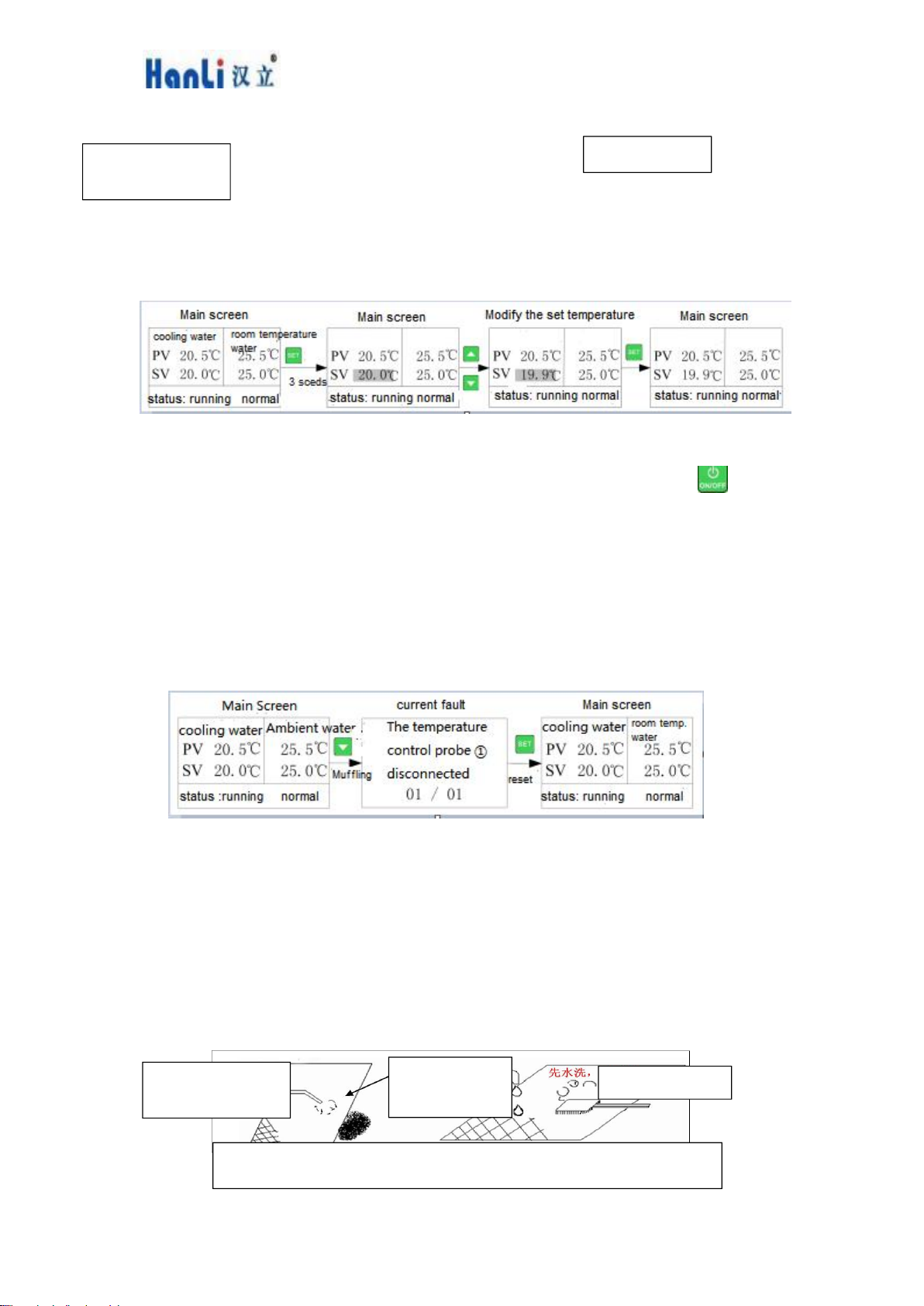
7.4.2 Integrated controller temperature display
The PV zone shows "actual temperature" and the SV zone shows "set temperature".
7.5 Parameter setting
7.5.1 Parameter setting of the split controller
In the non-fault state, press <▲>+<▼> at the same time to enter the low temperature water
setting temperature setting interface, the setting temperature xx.x is displayed flashing, at this time
the setting temperature can be modified by pressing <▲> or <▼> keys.
If no key operation is performed for 5 seconds after setting, the system will automatically save
the set value and exit the setting state.
Normal water set temperature = [Low temperature water set temperature] + [F01 Normal water
temperature difference], to change this ,you need to modify the factory parameter [F01 Normal
water temperature difference].
In the temperature display, press the <▲>+<▼> keys simultaneously for 5s to enter the
manufacturer's parameter setting status, the factory set parameters are generally not adjusted, if you
need to adjust, please seek the chiller manufacturer's agreement.
During the selection of the manufacturer's parameters, press <▼> to select the parameter item,
press <▲> to enter the parameter setting and exit the manufacturer's parameter setting after 15s of
operation without pressing the key (the display shows the parameter item).
For parameter setting, the parameter value can be modified by <▲> or <▼>, after 5S of
keyless operation or by pressing <▲>+< ▼> to return to the parameter selection and save (the
display flashes to show the parameter value).

User's Manual of Fiber Laser Chiller
20
7.5.2 LCD controller parameter setting
①, Quick change of set temperature
If the user parameter [Lock Temperature] is set to "No", the set temperature can be changed
directly in the main interface.
degrees, operating as follows:
[Remark 1]: The set temperature can also be modified in the user parameters.
[Note 2]: When changing the set temperature in dual temperature mode, press the key to
switch between low temperature water/ambient water
Set the temperature.
②、Inquiry/Reset Fault
When a fault occurs, an alarm appears in the main interface and the fault is queried and reset
as follows:
8 Maintenance
The equipment must be stopped and cut off after 3 minutes for maintenance, otherwise there
is a risk of electric shock. When the ambient temperature is below 2°C, the internal water must be
drained when the machine is shut down for a long time.
8.1 Dust control in summer
During the summer months, please dust and clean the condenser and dus+creen of the
equipment in about 15 days, as shown in Figure
Blow it with
compressed air
Blow it with
compressed air
Wash and dry
Wash and dry
Figure 11 Dust screen cleaning and dust removal process
Dustproof
mesh
Other manuals for HL-1000 Series
1
This manual suits for next models
22
Table of contents
Other HANLI Chiller manuals
Popular Chiller manuals by other brands

AERMEC
AERMEC WRL 200 Installation & maintenance manual

Johnson Controls
Johnson Controls York OptiView YK G Series Operation and maintenance

York
York YLCC-H technical information

Midea
Midea Aqua Tempo Super Series Technical & service manual

Lindab
Lindab CELO installation instructions

Sterling
Sterling GP20-50 Series Reference manual