4
ABBREVIATIONS AND EXPLANATIONS
Frequently used abbreviations in this manual include:
Factory-installed additional components are referred to as options
in this manual; factory-supplied but field-installed additional com-
ponents are referred to as accessories.
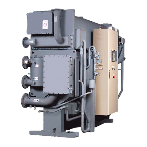
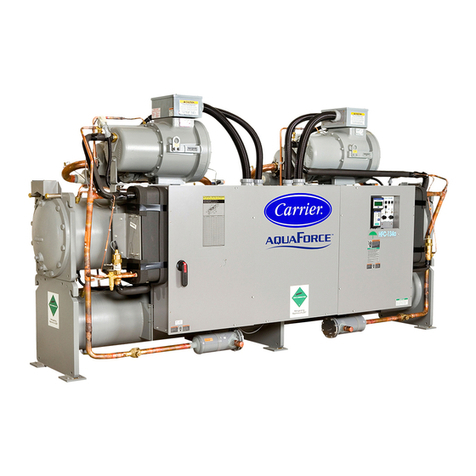
CHILLER FAMILIARIZATION (Fig. 1 and 2)
Chiller Information Nameplate
The information nameplate is located on the left side of the
chiller control panel.
System Components
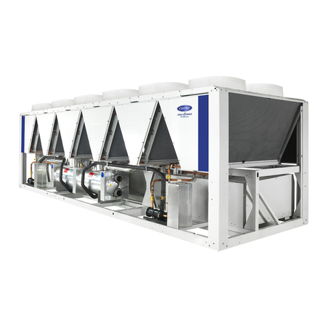
The main components include the evaporator and condenser
heat exchangers in separate vessels, motor-compressor, refrig-
erant, lubrication package, control panels, PIC6 Touch Screen
HMI, economizer, VFD, and purge system.
Evaporator
This vessel is located underneath the compressor. The evapora-
tor is maintained at a lower temperature/pressure so evaporat-
ing refrigerant can remove heat from water flowing through its
internal tubes. Water flows through the internal tubes to pro-
vide comfort or process cooling.
Condenser
The condenser operates at a higher temperature/pressure than the
evaporator and has water flowing through its internal tubes in or-
der to remove heat from the refrigerant. It contains a metering de-
vice that regulates the flow of refrigerant into the economizer.
Economizer
This chamber reduces the refrigerant pressure to an intermediate
level between the evaporator and condenser vessels. In the econ-
omizer, vapor is separated from the liquid, the separated vapor
flows to the second stage of the compressor, and the liquid flows
into the evaporator. The energy removed from the vaporized re-
frigerant in the economizer allows the liquid refrigerant in the
evaporator to absorb more heat when it evaporates and benefits
the overall cooling efficiency cycle. It contains a float assembly
that regulates the flow of refrigerant into the evaporator.
Motor-Compressor
This component maintains system temperature and pressure
differences and moves the heat-carrying refrigerant from the
evaporator to the condenser. The 19DV utilizes a two-stage
back to back direct drive configuration.
Purge Unit
This is a small independent condensing unit with compressor, sep-
arator, regenerative carbon filters, heater and vacuum pump. The
purge extracts gas from condenser (or from compressor if unit is
not in operation) and purifies it by removing non-condensable
gases and any water vapor that may be present.
Variable Frequency Drive (VFD)
The VFD variable frequency is a voltage source design that
converts line voltage into PWM (pulse width modulating) mo-
tor input for motor speed and torque control.
Refrigerant Lubrication System
This system provides lubrication to the compressor bearing by
means of a refrigerant pump.
Chiller Control Panel
This control panel includes the input and output boards (IOBs),
control transformer, relays, contactors, and circuit breakers. It pro-
vides the power distribution and protection to the electrical com-
ponents installed on chiller and has the following functions:
• Communication with PIC6 touch screen
• Communication with purge panel
• Communication with VFD
• Sensor input and outputs
• Actuators control
• Refrigerant pump control
CAUTION
WHEN FLUSHING THE WATER SYSTEMS isolate the
chiller from the water circuits to prevent damage to the heat
exchanger tubes.
CAUTION
This unit uses a microprocessor control system. Do not
short or jumper between terminations on circuit boards or
modules; control or board failure may result.
Be aware of electrostatic discharge (static electricity) when
handling or making contact with circuit boards or module
connections. Always touch a chassis (grounded) part to
dissipate body electrostatic charge before working inside
control center or use a grounding strap before handling
printed circuit boards.
Use extreme care when handling tools near boards and when
connecting or disconnecting terminal plugs. Circuit boards can
easily be damaged. Always hold boards by the edges and
avoid touching components and connections.
This equipment uses, and can radiate, radio frequency ener-
gy. If not installed and used in accordance with the instruc-
tion manual, it may cause interference to radio communica-
tions. The PIC6 control boards have been tested and found to
comply with the limits for a Class A computing device pur-
suant to International Standard in North America EN 61000-
2/3 which are designed to provide reasonable protection
against such interference when operated in a commercial en-
vironment. Operation of this equipment in a residential area
is likely to cause interference, in which case the user, at his
own expense, will be required to take whatever measures
may be required to correct the interference.
Always store and transport replacement or defective boards
in anti-static shipping bag.
AWG — American Wire Gage
BMS — Building Management System
CCN — Carrier Comfort Network®
DCIB — Digital Control Interface Board
DVM — Digital Volt-Ohmmeter
EC — Envelope Control
ECDW — Entering Condenser Water
ECW — Entering Chilled Water
EMS — Energy Management System
HMI — Human Machine Interface
HVIB — High Voltage Interface Board
I/O — Input/Output
IGBT — Insulated-Gate Bipolar Transistor
IGV — Inlet Guide Vane
IOB — Input Output Board
LCDW — Leaving Condenser Water
LCW — Leaving Chilled Water
LED — Light-Emitting Diode
MAWP — Maximum Allowable Working Pressure
NSTV — Network Service Tool V
OLTA — Overload Trip Amps
PIC — Product Integrated Controls
PPE — Protective Personal Equipment
PWM — Pulse Width Modulating
RLA — Rated Load Amps
RMS — Root Mean Square
SCCR — Short Circuit Current Rating
SCR — Silicon Controlled Rectifier
SIOB — Starfire 2 Input Output Board
TXV — Thermostatic Expansion Valve
VFD — Variable Frequency Drive
VPF — Variable Primary Flow
