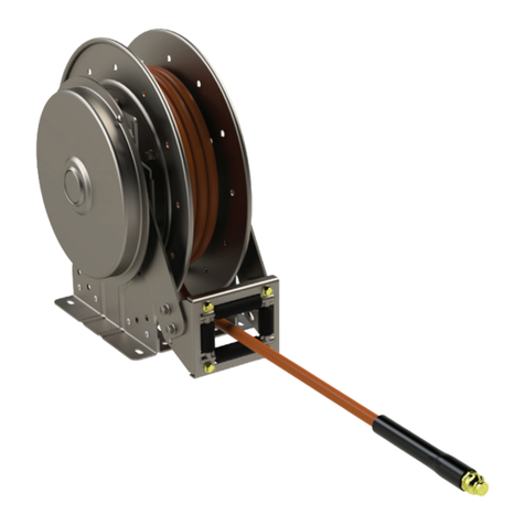
Hannay Reels N Series User manual

"B"
"A"
"B"
"A"
Hannay Reels, Inc.
553 State Route 143, Westerlo, NY 12193
www.hannay.com
Email: reels@hannay.com
Phone 1-518-797-3791
Toll Free 1-877-GO-REELS (467-3357)
Fax 1-800-REELING (733-5464)
Int’l Fax 1-518-797-3259
TSB 2013.07.001
Changing Roller Arm Positions:
“N-Series” Spring Reels
Affected Reels: N Series Spring Reel
Required Time: 15 min
Priority: Customer Request
Date Issued: July-2013
1 of 7 Form H-1305-TSB Rev 1
PDF 1-20
DESCRIPTION:
This TSB details adjusting the rollers on an “N-series” spring reel to various positions.
Changing Roller Position from “SR” to “VR” with a “J, K, or M” Spring ........................................Page 2
Changing Roller Position from “SR” to “TR” with a “J, K, or M” Spring.........................................Page 3
Changing Roller Position from “SR” to “VR” with a “A, B, D, F, G, or SA” Spring.........................Page 4
Changing Roller Position from “SR” to “TR” with a “A, B, D, F, G, or SA” Spring.........................Page 5
Changing Roller Position from “SR” to “VR” with a “C or L” Spring..............................................Page 6
Changing Roller Position from “SR” to “TR” with a “C or L” Spring ..............................................Page 7
SPRING SIZE GUIDE
Spring Type Can Diameter “B” Bolt Circle Diameter “A”
A 16.75” 19.12”
B 16.75” 19.12”
C 9” 10”
D 16.75” 19.12”
F 16.75” 19.12”
G 16.75” 19.12”
J 12.75” 13.38”
K 9” 10”
L 9” 10”
M 9” 10”
SA 16.75” 19.12”
INDEX:
Note: In the following gures (pages 2-7), the spring
mounting bracket and roller arms are highlighted by a
different color, this for representation only.
SR Roller Position VR Roller Position TR Roller Position

2 of 7 Form H-1305-TSB Rev 1
PDF 1-20
TSB 2013.07.001 : Changing Roller Arm Positions: “N-Series” Spring Reels
Figure 2 - Reel with Rollers in the “VR” Position
1. Remove spring per Hannay TSB
2013.06.003 Changing a Hannay Spring
Motor, this can be found at www.hannay.
com. The reel should look like Figure 1.
2. Make note of the spring bracket
mounting location, which will be moved
to the other side of the center hub.
3. Remove the 3/8” nuts and bolts holding
the spring mounting bracket and roller
arms to the frame.
4. Swing the Roller Bracket up to the VR
position (Figure 2), until the holes on
the bracket line up with the holes in the
frame. Replace and tighten the bolts.
5. Reposition the spring mounting bracket
as shown in Figure 2, using two 3/8”-16
x 0.75 spinlock bolts and two 3/8”-16
spinlock nuts. The reel should look like
Figure 2.
6. Remove the bottom bolts attaching the
roller assembly to the roller arms and
loosen the top bolts.
7. Rotate the roller assembly so that is it
pointed in the same direction as shown
in Figure 2.
8. Check that all bolts and nuts are tight.
9. Replace the spring per Hannay TSB
2013.06.003 Changing a Hannay Spring
Motor.
10. To go from a “VR” to an “SR” simply
reverse steps 1 – 9, discarding the bolts
and nuts from step 5.
Changing Roller Position from “SR” to “VR” with a “J, K, or M” Spring:
Figure 1 - Reel with Rollers in the “SR” Position

3 of 7 Form H-1305-TSB Rev 1
PDF 1-20
TSB 2013.07.001 : Changing Roller Arm Positions: “N-Series” Spring Reels
Figure 4 - Reel with Rollers in the “TR” Position
1. Remove spring per Hannay TSB
2013.06.003 Changing a Hannay Spring
Motor, this can be found at www.hannay.
com. The reel should look like Figure 3.
2. Make note of the spring bracket
mounting location so it can be reinstalled
later.
3. Remove the 3/8” nuts and bolts holding
the spring mounting bracket and roller
arms to the frame.
4. Move the Roller Arms to the “TR”
position (Figure 4) on the back side of
the reel. Align the holes and install the
bolts.
5. Reposition the spring mounting bracket
as shown in Figure 4, using two 3/8”-16
x 0.75 spinlock bolts and two 3/8”-16
spinlock nuts. The reel should look like
Figure 4.
6. Check that all bolts and nuts are tight.
7. Replace the spring per Hannay TSB
2013.06.003 Changing a Hannay Spring
Motor.
8. To go from a “TR” to an “SR” simply
reverse steps 1 – 7, discarding the bolts
and nuts from step 5.
Changing Roller Position from “SR” to “TR” with a “J, K, or M” Spring:
Figure 3 - Reel with Rollers in the “SR” Position

4 of 7 Form H-1305-TSB Rev 1
PDF 1-20
TSB 2013.07.001 : Changing Roller Arm Positions: “N-Series” Spring Reels
Figure 6 - Reel with Rollers in the “VR” Position
1. Remove spring per Hannay TSB
2013.06.003 Changing a Hannay
Spring Motor, this can be found
at www.hannay.com. The reel
should look like Figure 5.
2. Make note of the spring bracket
mounting location so it can be
reinstalled later.
3. Remove the 3/8” nuts and bolts
holding the spring mounting
bracket and roller arms to the
frame.
4. Swing the Roller Arms up to the
VR position (Figure 6), until the
holes on the roller and the spring
brackets line up with the holes
in the frame, replace and tighten
the bolts.
5. Remove the bottom bolts
attaching the roller assembly to
the roller arms and loosen the
top bolts.
6. Rotate the roller assembly so
that is it pointed in the same
direction as shown in Figure 6.
7. Check that all bolts and nuts are
tight.
8. Replace the spring per Hannay
TSB 2013.06.003 Changing a
Hannay Spring Motor.
9. To go from a “VR” to an “SR”
simply reverse steps 1 – 8.
Changing Roller Position from “SR” to “VR” with an “A, B, D, F, G, or SA” Spring:
Figure 5 - Reel with Rollers in the “SR” Position

5 of 7 Form H-1305-TSB Rev 1
PDF 1-20
TSB 2013.07.001 : Changing Roller Arm Positions: “N-Series” Spring Reels
Figure 8 - Reel with Rollers in the “TR” Position
1. Remove spring per Hannay TSB
2013.06.003 Changing a Hannay
Spring Motor, this can be found
at www.hannay.com. The reel
should look like Figure 7.
2. Make note of the spring bracket
mounting location it can be
reinstalled later.
3. Remove the 3/8” nuts and bolts
holding the spring mounting
bracket and roller arms to the
frame.
4. Move the Roller Arms to the “TR”
position (Figure 8) on the back
side of the reel. Align the holes
and install the bolts.
5. Reposition the spring mounting
bracket as shown in Figure 8,
using two 3/8”-16 x 0.75 spinlock
bolts and two 3/8”-16 spinlock
nuts. The reel should look like
Figure 8.
6. Check that all bolts and nuts are
tight.
7. Replace the spring per Hannay
TSB 2013.06.003 Changing a
Hannay Spring Motor.
8. To go from a “TR” to an “SR”
simply reverse steps 1 – 7,
discarding the bolts and nuts
from step 5.
Changing Roller Position from “SR” to “TR” with an “A, B, D, F, G, or SA” Spring:
Figure 7 - Reel with Rollers in the “SR” Position

6 of 7 Form H-1305-TSB Rev 1
PDF 1-20
TSB 2013.07.001 : Changing Roller Arm Positions: “N-Series” Spring Reels
Figure 12 - Reel with Rollers in the “VR” Position
1. Check if the arm holding the roller assembly to the frame is the same as in Figure 10. If you don’t have
the same arm you must order p/n 9941.0031.
Changing Roller Position from “SR” to “VR” with a “C or L” Spring:
Figure 11 - Reel with Rollers in the “SR” Position
2. Remove spring per Hannay TSB
2013.06.003 Changing a Hannay
Spring Motor, this can be found at
www.hannay.com. The reel should
look like Figure 11.
3. Remove the nuts and bolts holding
the roller arms to the frame.
4. Swing the Roller Bracket up to the
VR position (Figure 12) until the
holes on the roller arms line up with
the holes in the frame. Replace and
tighten the bolts.
5. Remove the bottom bolts attaching
the roller assembly to the roller
arms and loosen the top bolts.
6. Rotate the roller assembly so that is
it pointed in the same direction as
shown in Figure 12.
7. Check that all bolts and nuts are
tight.
8. Replace the spring per Hannay TSB
2013.06.003 Changing a Hannay
Spring Motor.
9. To go from a “VR” to an “SR” simply
reverse steps 1 – 8.
Figure 9 - Old Style Roller Arm (9941.0030) Figure 10 - New Style Roller Arm (9941.0031)
Models Built after October 2013

7 of 7 Form H-1305-TSB Rev 1
PDF 1-20
TSB 2013.07.001 : Changing Roller Arm Positions: “N-Series” Spring Reels
Figure 16 - Reel with Rollers in the “VR” Position
1. Check if the arm holding the roller assembly to the frame is the same as in Figure 14. If you don’t have
the same arm you must order p/n 9941.0031.
Changing Roller Position from “SR” to “TR” with a “C or L” Spring:
Figure 15 - Reel with Rollers in the “SR” Position
2. Remove spring per Hannay TSB
2013.06.003 Changing a Hannay
Spring Motor, this can be found at
www.hannay.com. The reel should
look like Figure 15.
3. Remove the nuts and bolts holding
the roller arms to the frame.
4. Move the Roller Arms to the “TR”
position (Figure 16). On the back
side of the reel, align the holes and
install the bolts.
5. Rotate the roller assembly so that is
it pointed in the same direction as
shown in Figure 16.
6. Check that all bolts and nuts are
tight.
7. Replace the spring per Hannay TSB
2013.06.003 Changing a Hannay
Spring Motor.
8. To go from a “TR” to an “SR” simply
reverse steps 1 – 8, discarding the
two new bolts from step 5.
Figure 13 - Old Style Roller Arm (9941.0030) Figure 14 - New Style Roller Arm (9941.0031)
Models Built after October 2013
Table of contents
Other Hannay Reels Tools manuals
Popular Tools manuals by other brands

Williams
Williams 61SMW Operation manual
Fein
Fein MULTIMASTER FMM 250 user guide

KAN-therm
KAN-therm AC 3000 Instructions for use

Bench Dogs
Bench Dogs Carpenter Square instruction manual

Farmnavigator
Farmnavigator AvMap RTK quick guide
Matatakitoyo Torque Tools
Matatakitoyo Torque Tools MIT2 Operation manual
