Hantek 1060 User manual


USER’S MANUAL
060 / 200 / 500 / 600 / 600H

2
Content
Safety Notice …………………………………………………..3
Digital Scope Meters………………………..……………
…
…5
CHAPTER 1: Getting Start…………………………………... 6
General Check……………………………………
…
....6
User’s Interface……………………………………...…6
Input Connections…………………………………
....
.11
Function Check…………………………………
…
….12
To compensate probes…………………………
…..
...13
To display a signal automatically…………………....15
Using the Scope Meter……………………………
...
.15
CHAPTER 2: Operating Scope……………………………..18
Set Vertical System……………………………
…….
..18
Set Horizontal System…………………………
…….
.32
Set Trigger System………………………………
…..
.36
Save / Recall Waveforms and Setups……………...42
Utility Function……………………………
…………
...46
Signal Measurement……………………………
…..
..55
Cursor Measurement…………………………
….......
57
CHAPTER 3: Using examples…………………………
…...61
CHAPTER 4: Multimeter………………………………….....69
CHAPTER 5: Troubleshooting………………………
……
...80
CHAPTER 6: Specications……………
………………
…...81
CHAPTER 7: Appendix.....................................................84

General Safety Notice
1. Safety Terms and Symbols
Terms in this manual:
These terms may appear in this manual:
WARNING: Warning statements identify conditions or practices that could result in
injury or loss of life.
CAUTION: Caution statements identify conditions or practices that could result in
damage to this product or other property.
Terms on the Product:
These terms may appear on the product:
DANGER: indicates an injury hazard may be immediately accessible.
WARNING: indicates an injury hazard may be not immediately accessible.
CAUTION: indicates that a potential damage to the instrument or other property
might occur.
Symbols on the Product:
These symbols may appear on the product:
2. General Safety Information
Carefully read the following safety information in order to avoid any personal injury
or damage on this product or any products connected with it. Review the following
safety precautions carefully before operate the device to avoid any personal injuries or
damages to the device and any products connected to it. To avoid potential hazards use
the device as specied by this user’s manual only.
■ To Avoid Fire or Personal Injury.
■ Use Proper Power adapter. Use only the power cord specied for this product

and certied for the country of use.
■ Connect and Disconnect Properly. Do not connect or disconnect probes or test
leads while they are connected to a voltage source.
■ Connect and Disconnect Properly. Connect the probe output to the
measurement device before connecting the probe to the circuit under test. Disconnect
the probe input and the probe reference lead from the circuit under test before
disconnecting the probe from the measurement device.
■ Observe All Terminal Ratings. To avoid re or shock hazard, observe all ratings
and markings on the product. Consult the product manual for further ratings information
before making connections to the product.
■ Use Proper Probe. To avoid shock hazard, use a properly rated probe for your
measurement.
■ Avoid Circuit or Wire Exposure. Do not touch exposed connections and
components when power is on.
■ Do Not Operate With Suspected Failures. If suspected damage occurs with the
device, have it inspected by qualied service personnel before further operations.
■ Provide Proper Ventilation. Refer to the installation instructions for proper
ventilation of the device.
■ Do not operate in Wet/Damp Conditions.
■ Do not operate in an Explosive Atmosphere.
■ Keep Product Surfaces Clean and Dry.

5
Digital Scope Meters
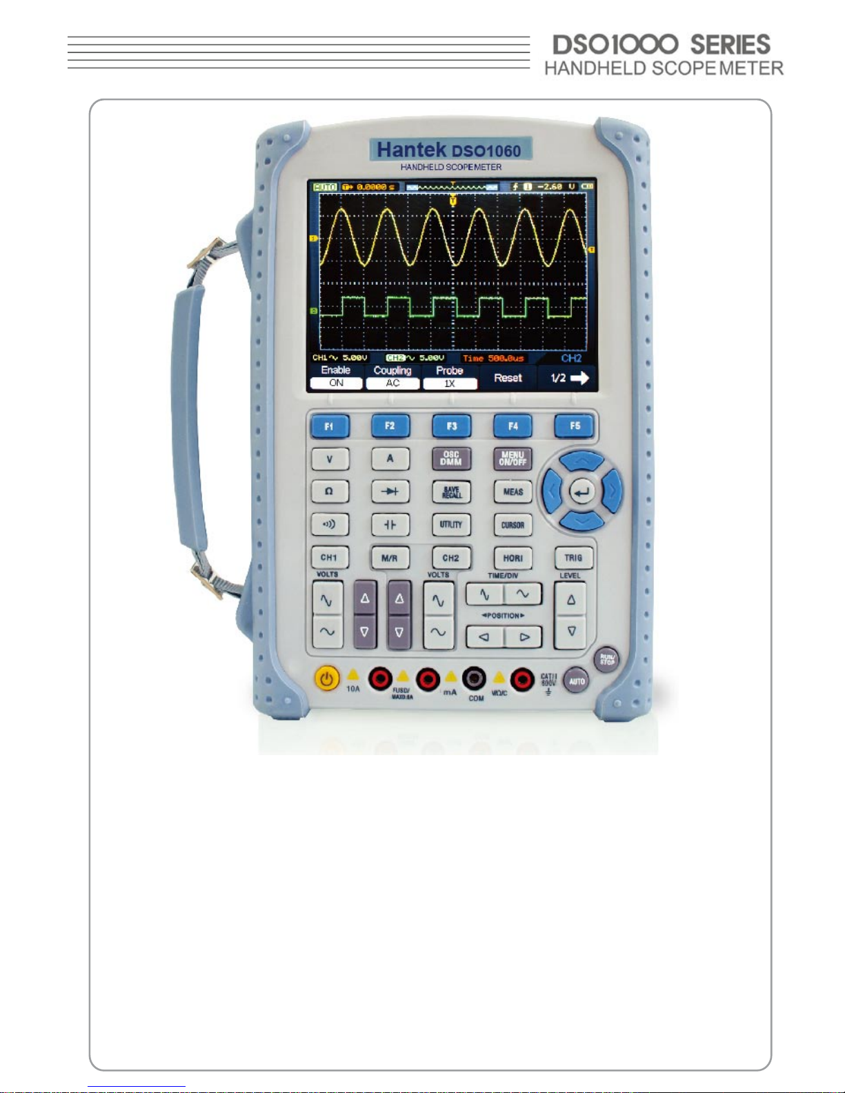
DSO1000 Series digital scope meters offer exceptional waveform viewing and
measurements in a compact, lightweight package. DSO1000 series is ideal for
production test, eld service, research, design, education and training involving
applications of analog circuit tests and troubleshooting.
Product features:
■ Dual Channel, Bandwidth:
60MHz (DSO1060)
200MHz (DSO1200)
500MHz (DSO1500)
600MHz (DSO1600)
600MHz (DSO1600H)
■ Maximum real-time sampling rate:
150MSa/s (DSO1060)
250MSa/s (DSO1200)
500MSa/s (DSO1500)
1GSa/s (DSO1600)
2GSa/s (DSO1600H)
■ Memory depth:
32K points (Single Channel), 16K points (Dual Channels)
■ Color TFT LCD, 320×240 pixels resolution.
■ USB storage and printing supports, rmware upgrade via USB interface.
■ Adjustable waveform intensity, more effective waveform viewing.
■ One-touch automatic setup, ease of use (AUTOSET).
■ 15 Waveforms, 15 setups, supports CSV and bitmap format.
■ 22 Automatic measurements.
■ Automatic cursor tracking measurements.
■ Waveform recorder, record and replay dynamic waveforms.
■ User selectable fast offset calibration.
■ Built-in FFT function, Frequency Counter.
■ Pass/Fail Function.
■ Addition, Subtraction, Multiplication and Division Mathematic Functions.
■ Advanced trigger types include: Edge, Pulse width.
■ Multiple Language User Interface.
■ Pop-up menu makes it easy to read and easy to use.
■ Built-in multi-language help system.
■ Easy-to-use le system supports Multi-Language characters le name
input.
■ Selectable 20 MHz bandwidth limit;

6
CHAPTER 1: Getting Start
This chapter covers the following topics:
■ General Check
■ Functional Check
■ The User Interface
■ Input Connections
■ To compensate probes
■ To display a signal automatically
■ Using the Scope Meter
General Check
When you have got a new DSO1000 series scope meter, it is suggested that you
should perform a general inspection on the instrument according to the following steps:
■ Check the shipping container for damage:
Keep the damaged shipping container or cushioning material until the contents of the
shipment have been checked for completeness and the instrument has been checked
mechanically and electrically.
■ Check the accessories:
Accessories supplied with the instrument are listed in “Accessories” in this guide. If the
contents are incomplete or damaged,please notify our distributor at your local area or
the overseas sales dept.
■ Check the instrument:
In case there is any mechanical damage or defect, or the instrument does not operate
properly or fails performance tests, please notify our distributor at your local area or the
overseas sales dept.
User’s Interface
The rst thing to do with a new scope meter is to know its front panel. This chapter
helps to be familiar with the layout of the keys and how to use them. Read this chapter
carefully before further operations.
Front Panel (Figure 1-1):
The buttons not only allow you to use some of the functions directly but also bring
up the manual keys on the screen, which enable the access to many measurement
features associated with advanced functions, mathematics, and reference or to run
control features.

Figure 1-1
Scope Meter Front Panel

Figure 1-2
Front Panel Description
Description
1. LCD Display
2. F1~F5: Sets or switch options for the menu
3. Arrow Keys
4. Hori: Shows Horizontal menu
5. TRIG: Shows Trigger menu
6. Level: Adjust the trigger level

7. RUN/STOP: key for running or stopping the operation
8. AUTO: Be used for auto setting under the oscilloscope operation mode
9. TIME/DIV: Decrease or Increase the time base
10. POSITION: Adjust the horizontal trigger position
11. CH2: Shows the CH2 menu
12. VOLTS: Decrease or Increase the voltage/div
13. CH1: Shows the CH1 menu
14. M/R: Shows the Math or REF menu
15. DMM Buttons: The DMM control buttons
16. DMM/SCOPE: Switch DMM or Scope function
17. MENU ON/OFF: Turn on/off the menu
18. SAVE RECALL: Shows SAVE or RECALL menu
19. MEAS: Shows Measurement menu
20. UTILITY: Shows Utility menu
21. CURSOR: Shows Cursor menu
Display screen
Figure 1-3

0
LCD Display screen
Description
1. Shows running status.
2. Shows delay time
3. Shows location of the current waveform in the memory.
4. Shows the trigger position in the memory.
5. Shows the trigger mode.
6. Shows the trigger source.
7. Shows the trigger level.
8. Shows the power.
9. The center of current waveform window.
10. CH1 waveform.
11. The trigger level symbol.
12. The grid
13. CH2 waveform.
14. Shows the time base.
15. Shows the menu title.
16. The menu
17. CH1/CH2
18. Shows the coupling.
19. Shows the voltage/div.
20. CH2 mark.
21. CH1 mark.
22. Shows the trigger position in current waveform window.

Input Connections
See the following Figure 1-4:
Figure 1-4
Input Connections
Description:
1. The power adapter is supplied for AC power supply and battery recharging.
2. Multi-meter input jacks, including four circular banana jacks .The four circular jacks
are used for voltage,resistance,mA range current and A range current inputs.
3. Multi-meter test lead.
4. Scope Meter probes.
5. Scope Meter input channels.

2
Function Check
Perform this quick functional check to verify that your scope meter is operating correctly.
1. Turn on the instrument.
Use the power adapter designed for your scope meter only. Use a power source that
delivers 100 to 240 VACRMS, 50Hz. Turn on the scope meter.
2. Input a signal to a channel
Set the attenuation switch on the probe to 10X and connect the probe to Channel 1 on
the scope meter.
To do this:
■ Align the slot in the probe connector with the key on the CH 1 BNC connector.
■ Push to connect, and twist to the right to lock the probe in place.
■ Attach the probe tip and ground lead to the PROBE COMP connector.
Set the probe attenuation of the scope meter to 10X.To do this, push CH1→Probe→10X.
Figure 1-5
Set the probe
Push the AUTO button. Within a few seconds, a square wave will display
(approximately 1 kHz 2 V peak- to- peak).
Turn off Channel 1 and turn on Channel 2, repeat steps 2 and 3.

To compensate probes
Perform this adjustment to match the characteristics of the probe and the channel input.
This should be performed whenever attaching a probe to any input channel the rst time.
1. From CH1 menu, set the Probe attenuation to 10X (press CH1→Probe→10X).
Set the switch to 10X on the probe and connect it to CH1 of the scope meter.
When using the probe hook-tip, insert the tip onto the probe rmly to ensure proper
connection.
Attach the probe tip to the Probe compensator connector and the reference lead to the
ground pin, Select CH1, and then press AUTO.
2. Check the shape of the displayed waveform.
Correctly Compensated

Over compensated
Under Compensated
3. If necessary, use a non-metallic tool to adjust the trimmer capacitor of the probe for
the attest square wave being displayed on the scope meter.
4. Repeat if necessary.
WARNNING: To avoid electric shock while using the probe, be sure the perfection of
the insulated cable, and do not touch the metallic portions of the probe head while it is
connected with a voltage source.

5
To display a signal automatically
The scope meter has an Auto feature that automatically sets up the scope meter to best
display the input signal. Using Auto requires signals with a frequency greater than or
equal to 50 Hz and a duty cycle greater than 1%.
Press the AUTO button, the scope meter turns on and scales all channels that have
signals applied, and it selects a time base range based on the trigger source. The trigger
source selected is the lowest numbered input that has a signal applied. The scope meter
has two-channels input . Connect a signal to the channel 1 input.
1.Connect a signal to the scope meter.
2.Press AUTO.
The scope meter may change the current setting to display the signal. It will
automatically adjust the vertical and horizontal scaling, the trigger coupling, type,
position, slope, level, and mode settings.
Using the Scope Meter
This part provides a step-by-step introduction to the scope functions. The introduction
does not cover all of the capabilities of the scope functions but gives basic examples to
show how to use the menus and perform basic operations.
Turn on the scope meter
Connect scope meter to AC power via a power adapter. (The scope meter can still work
with built-in Li-ion battery even without AC power supply.)
Turn the scope meter on by pressing down the power on/off key.
The instrument then performs Self-checking after power on. The welcome picture will
display on the screen when the system nishes Self-checking.
The scope meter is powered up in its last setup conguration.

6
Figure 1-6 The Login window
Menu Operation
The following example shows how to use the tools menus to select a function, as shown
in the following gure.
Figure 1-7 The Menu

1. Press the MENU ON/OFF key to display the Function Menu on the bottom of the
screen and the corresponding optional settings on the bottom. Press MENU ON/OFF
again to hide the Function Menu.
2. Choose one key from F1 to F5 and press it to change function setting.
Set up the vertical system
1. Change the vertical setup and notice that each change affects the
status bar differently.
■ Change the vertical sensitivity with or button and notice the change in the
status bar.
2. Move the signal vertically.
■ The / button moves the signal vertically. Also notice that the channel symbol on
the left side of the display moves in conjunction with the button.
To set up the horizontal system
1. Change the time base.
■ The or button changes the time base in a 1-2-5 step sequence, and displays
thevalue in the status bar.
2. Move signal horizontally.
■ The or button moves displayed signal horizontally on waveform window. It sets
the trigger point position.
Set up the trigger system
1. Change the trigger Level
■ The or button changes the trigger level. The trigger level value is displayed
at the top-right of the screen and a line is displayed showing the location of the trigger
level.
2. Change the trigger setup and notice these changes in the status bar.
■ Press TRIG button in the key panel.
Choose one key from F1 to F5 and press it to change function setting.

CHAPTER 2: Operating Scope
The end user should know how to determine the system setup from the status bar of a
Scope Meter. This chapter will detail the scope meter function of the test tool.
■ Set Vertical System
■ Set Horizontal System
■ Set Trigger System
■ Save and Recall waveforms and setups
■ Utility Function
■ Measure Signal
■ Cursor Measure
Set Vertical System
Each channel of Scope meter has its own independent operation menu and it will pop up
after pressing CH1 or CH2 button. The settings of all items in the menu are shown in the
table below.
To make vertical CH1 and CH2 settings, do the following:
1. Press the CH1 or CH2 button and then the function menu appears at the bottom of
the screen.
2. Select and press key from F1 to F5 keys to make different settings.
Now, you can nd the menu that looks like the following gure 2-1.
The CH1 menu (Page 1/2)
The CH1 menu (Page 2/2)
Figure 2-1
The CH1 Menu
The following table describes the channel menu:
Other manuals for 1060
1
This manual suits for next models
4
Table of contents
Other Hantek Multimeter manuals
Popular Multimeter manuals by other brands

Gossen MetraWatt
Gossen MetraWatt METRAmax 2 operating instructions

Actron
Actron Digital Multimeter CP7676 operating instructions

Harbor Freight Tools
Harbor Freight Tools 63759 Owner's manual & safety instructions

Maxwell Digital Multimeters
Maxwell Digital Multimeters 25103 user manual

Conrad
Conrad M-3890DT operating instructions

Emos
Emos M0230 manual