YSI ProDSS User manual

MULTIMETER: YSI-ProDSS
EQUIPMENT NEEDED
•YSI-ProDSS multimeter
•(Sampling wand, float, tub, scoop)
•Data sheet, clipboard, pencil
Storage notes:
•
The battery may be damaged if kept in an
environment outside the range of -20 - 60°C
(-4° - 140°F).
•
When taking the ProDSS out into the field,
travel with ¼ cup of tap water in the
calibration cup.
•
When storing the ProDSS for longer than
one week, if possible, store in expired pH4
buffer solution, with the cup upright and the
probes submerged in the buffer.
NOTE 2015-16:
We purchased one instrument
in summer 2015 in the expectation of
purchasing a second and making it our
standard field water-quality testing equipment
in summer 2016. Meanwhile, we are
experimenting with settings and field
instructions, and recording values side-by-side
with our current equipment.
INITIAL INSTRUMENT PREPARATION:
1.
CABLE CONNECTION
Inspect the cable connection between the
handheld meter and the cable. If cable is not
connected to the meter,
make sure the
connectors are clean and dry before
connecting!
If connecters are clean and dry,
align the keys on the cable assembly connector
with the slots on the instrument connector.
Push together firmly, and
then twist the outer ring
clockwise until it locks
into place. The metal pin
should “snap” into place
and be visible through
small hole in the outer
ring (see image).
2.
SENSORS AND GUARD CHECK
If any of the individual sensors are not
connected, refer to “Settings and
Troubleshooting” section for sensor installation.
If there is an empty “slot” with no sensor
installed,
a port plug or sensor must be
installed or the bulkhead will be
damaged!
1. Remove calibration cup by backing off a bit
on the retaining nut in a counterclockwise
direction (see diagram). DO NOT REMOVE
THE RETAINING NUT; JUST LOOSEN IT!
(For a 4-second video, see
https://youtu.be/Z6b7YF1ONo0.)
2. Slide the cup off and set it aside on its pack,
slightly angled to hold the water inside.
3. Firmly hold the bulkhead with one hand and
turn the sensor guard counter-clockwise
until completely unthreaded. Set aside the
sensor guard in a clean dry place. Use
caution once the sensors are exposed!
4. Conduct a quick visual inspection of the
sensors; clean any debris on the sensor tips
with a lint-free cloth and rinse with water
.
Carefully “test” the connection of each
sensor by grasping the sensor near the
bulkhead between your thumb and finger,
and try to turn the sensor to determine if it
is loose. If the sensor moves or twists at
all (sensors should firmly be in place),
Do not
remove
this ring!
Simply
loosen
the
ring to
slide
the
entire
cup off.

YSI ProDSS
Field Procedures 2 18th Edition, 2016
reconnect the sensor guard and inform the
team leader. (See “Settings and
Troubleshooting,” below, under “Sensor
Installation”.) If sensors are firmly in place,
proceed to next step.
5. Carefully slide the sensor guard over the
sensors and push it toward the bulkhead
until the sensor guard threads align with the
bulkhead threads. Carefully finger-tighten
the sensor guard clockwise.
NOTE:
If any resistance is felt, loosen the
sensor guard completely to prevent cross-
threading. Incorrect installation may cause
damage to the sensor guard or bulkhead.
PREPARING FOR SAMPLING:
1. Turn on the meter by pushing the power
key . (To turn off the meter, hold down
the power key for 1.5 seconds.) If the
meter does not turn on, inform the team
leader and see the “Settings and
Troubleshooting” section under “Battery
Troubleshooting”.
Charging the Internal Li-Ion Battery Pack
Use YSI designated charging equipment only!
If the battery is not charged, the meter
must be charged from the AC power adapter
(strongest charge source)
, directly from a
computer USB connection, or from an
external, portable USB battery pack. When
using the AC adapter, turn the unit on first
so it recognizes the AC adapter. Once the
charging signal appears on the screen, it
can be turned off. It takes approximately
14 hours to charge the ProDSS battery with
the unit turned off. For maximum battery
life, if practical, don’t charge until the
battery is ≤40%, and bring the battery back
up to ≥80%.
Expected battery life:
• 20 hours at 25% (default) LCD brightness
• 14 hours at 100% LCD brightness
2. Study the main “Run” screen (see picture).
Confirm the following:
•The battery charge is >10%. If not,
inform your team leader.
•The date and time are correct:
The date and time should be displayed at
the top of the screen; if not, refer to the
“Settings and Troubleshooting” section
under “Date/Time”.
•Logging is correct:
At the top of the screen in the green bar,
it should read “Log One Sample”; if not,
refer to the “Settings and
Troubleshooting” section under “Logging
Data”.
•Individual parameter units are
correct:
temperature - °C
barometric pressure – inHg
dissolved oxygen saturation – DO %L (local)
dissolved oxygen concentration – DO mg/L
specific conductivity (at 25 °C)–SPC µS/cm
salinity – SAL psu (similar to ppt)
pH
turbidity – FNU (similar to NTU)
If any parameters shown above are not
displayed or do not match the units on the
photo below, notify your team leader and
refer to the “Settings and Troubleshooting”
section under “Sensor Display Details”.

YSI ProDSS
Field Procedures 3 18th Edition, 2016
Select your Site
:
a) Select the
System
button , then
highlight
Logging [single]
by using the
down arrow.
(Note: the green band
indicates which feature is highlighted.)
Select this feature by hitting Enter.
b) Before selecting a site, make sure the
Use Site List
check box has been
selected and
Use Data ID List
and
Continuous Mode
are not selected.If
not, highlight rows and hit Enter as
needed for the screen to look like this:
c) Highlight the line with
Site[XXXYYY]
. Hit
Enter.
d) You will see a list of sites. Scroll down
until you find your site name, and hit
Enter.If you can’t find your site, select
“test” and note on your field sheet the
site and time.
e) The green bar should read
Select [your
site].
Hit Enter, then hit Escape twice.
This will return you to the Run screen.
SAMPLING:
1.
Let the unit soak in the stream for 5-10
minutes,
in a place where it’s safe and
won’t get fouled by bottom sediment. If
you can put it at the sampling point, all the
better—see below.
2.
Place the probe at the sampling point:
Standing downstream or to the side of the
probe, place it in the main current, in a
place with steady flow, adequate depth,
good mixing, and no surface turbulence.
Do not sample downstream of where
your team has disturbed the bottom.
Sample at mid-depth, or 8-12” below the
surface if the water is deep. You may dangle
the probe or place it on clean rocks at the
bottom if the stream is shallow.
You must
immerse the probe at least halfway up
the guard.
Agitate the probe under water
to dislodge any bubbles at the probe tips.
The goal is always to get a representative,
well-mixed portion of the stream. Here are
some alternative sampling methods:
•Hold the probe out in the stream with a
wand and a float of some kind (an empty
bottle or piece of wood), at mid-column or
8-12” under (whichever is shallower).
•If there’s too much current to hold the
probe at the end of the wand out in the fast
water, you can wade out into the faster part
of the water column (if it’s safe) and hold
the probe pointing straight down into the
water with the wand.
•In extremely low water, here are a few
possibilities:
oPull some of the rocks out of the middle
of the creek, or build up rocks on the
sides, to create a little chute to deploy
the probe in.
oBuild a little rock dam and deploy the
probe in the pool it creates. Leave
enough time to let the disturbed
sediment settle out.
oCollect water in the tub included in the
field kit’s dirty bag (you might have to
use something as a scoop) and do the
measurements in there. if possible, sit
the bucket down in the stream to keep it
cool. Change out the water after you’ve
let the probe pre-soak in the first batch
for a few minutes.
3.
Stabilize and log readings:
Turn on the Auto Stable feature:
a) Hit the
Probe button
, then select
Auto Stable.
b) Confirm settings:

YSI ProDSS
Field Procedures 4 18th Edition, 2016
Parameters are
all set to [On]
(ISE=pH)
•
Audio
Enabled,
Continuous
Mode
and
Log Samples
boxes are
checked
•
Sample
Period(s)
is
set to a
number
•
Sample Count
is set to a number.
c)
Stabilize:
Hit the up arrow and select
Start Auto Stable.You’ll return to the
Run screen. On the Run screen, there
will be a flashing red symbol next to
each parameter. Wait until all of these
flashing red symbols
become green and
stay green for at
least two minutes
(use the on-screen
clock). Also
observe the
readings
(particularly
temperature, DO,
and pH) to look for
drift.
d)
Log a reading:
Once you’re sure that all parameters
have stabilized, press Enter to log a
reading.
The first time you hit Enter,
it will probably just light up the
darkened screen; you have to hit
Enter again before it will say
“Sample Logged” at the bottom.
Anytime the screen is dark, hitting any
button just brightens it.
Jumping Values: If readings won’t stabilize
…you can still record the readings, but you’ll
need to estimate values for the non-stable
parameters.
--If turbidity values oscillate, watch them for
several minutes and estimate the average, to
the nearest whole number, considering both the
extremes and most frequent numbers. If
needed, we might be able to calculate the
average at the office.
--If DO readings stabilize or overly slowly or not
at all, the DO Sensor Cap might be failing.
Check if more than a third of the black paint is
missing from the face of the sensor.
--Notify program staff of any problems.
3.
Record the data:
If possible, record the
data directly off the Run Screen right after
you’ve logged your sample. It is also
possible to retrieve the data either directly
from the meter or by linking the meter to a
computer—see instructions at end of
protocol.
Record the readings on your data sheet, in
the following order, using our rounding
convention (see Quality Assurance
protocol):
a)
Temperature:
to nearest 0.1°C
b)
Pressure:
to nearest 0.01 inHg
c)
DO Saturation (local):
to nearest %
d)
DO Concentration:
to nearest 0.1
mg/L
e)
Specific Conductivity:
to nearest
whole µS (microSiemens)
f)
Salinity:
to nearest 0.1 PSU (Practical
Salinity Units—similar to parts per
thousand)
g)
pH:
to nearest 0.1
h)
Turbidity:
to nearest whole FNU
4.
If you’re taking replicates at this site:
Remove probes from stream, shake off
water, and replace in stream. Then stabilize
and record a second reading; you may have
to press Enter twice.
5.
Perform a
Dissolved Oxygen
drift
check:
Remove probes from stream. Rinse
with purified water if the stream was dirty.
Then shake off any water droplets from the
DO sensor tip and temperature sensor; you
can also insert a lint-free cloth through the
open slots in the sensor guard. The

YSI ProDSS
Field Procedures 5 18th Edition, 2016
temperature sensor does not need to be
completely dry at its base. Then:
a) Pour a small amount of clean water
(1/8th inch) gently down the side of the
calibration cup.
b) Gently insert the sensor and guard into
the calibration cup and partially tighten
the calibration cup to the bulkhead.
NOTE: Do not fully tighten the cup;
atmospheric venting is required for
accurate calibration. Make sure the DO
and temperature sensors are not
submerged in water.
c) Set the unit aside right side up in the
shade and wait 5 to 15 minutes for
complete air saturation.
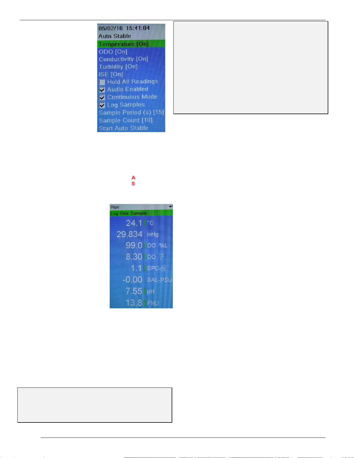
d) Wait for the unit to stabilize to these
criteria: During a period of 2
minutes, both DO % Local and
Temp (°C) stay within ± 0.1 of their
initial readings.
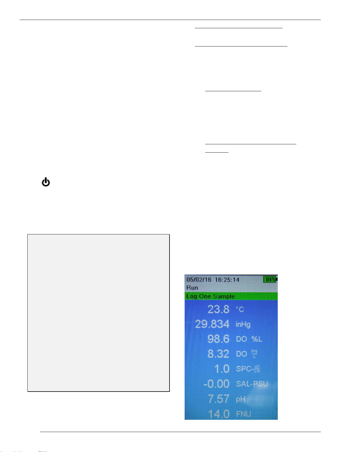
e) In Local DO% mode, the meter should
read 100% ±2%.(If it does not, try
unscrewing the sensor guard and
carefully dabbing the DO sensor tip with
a Kimwipe, then test again.)
f) Record the reading.
6. Record the meter number.
7.
If you are not submitting the data to Clallam
County
, record the latest calibration dates
for all parameters. Select the
File
button,
View GLP
, and scroll to see when the
instrument was last calibrated for each
parameter.
COMMON SENSE AND EXPECTED RANGES:
Please compare your readings with the expected
ranges on the datasheet. If you’re outside the
expected range, consider re-sampling or
troubleshooting with your fellow samplers. A couple
of common problems:
Conductivity readings <25 µS: You might not
have held the probe completely underwater. Try
taking another set of readings.
Turbidity readings <0: This is probably a sign of
contamination during zero calibration at the office;
report the problem to staff, who can re-run the zero
calibration without having to re-run the other
turbidity calibration settings.
8. If you performed replicates, check the
“Water Chemistry—General” protocol to see
if your pairs of readings are within the
acceptable precision limits; resample as
needed.
9. Record time and full initials of the
sampler; this should be someone who has
been properly trained (see “Quality
Assurance” protocol).
10.Turn off the meter (hold the Power
button), make sure the calibration cup is on
tight, and place the unit in the field bag.
Retrieving data from the meter
Retrieving from the meter’s data files:
Select the
File
button and select View Data and
Show Data. (If no data is displayed, make sure
you have the right date and time entered at the
bottom.) Find the bottom row for the site you
want, which should be the last set of data
recorded when you hit Enter to log your reading
at that site.(If you took a field replicate at this
site, this last row will be those replicate
readings; you’ll have to scroll back up a bit to
find your primary sample readings.) To see the
data readings for each parameter, hit the Right
Arrow key to scroll.
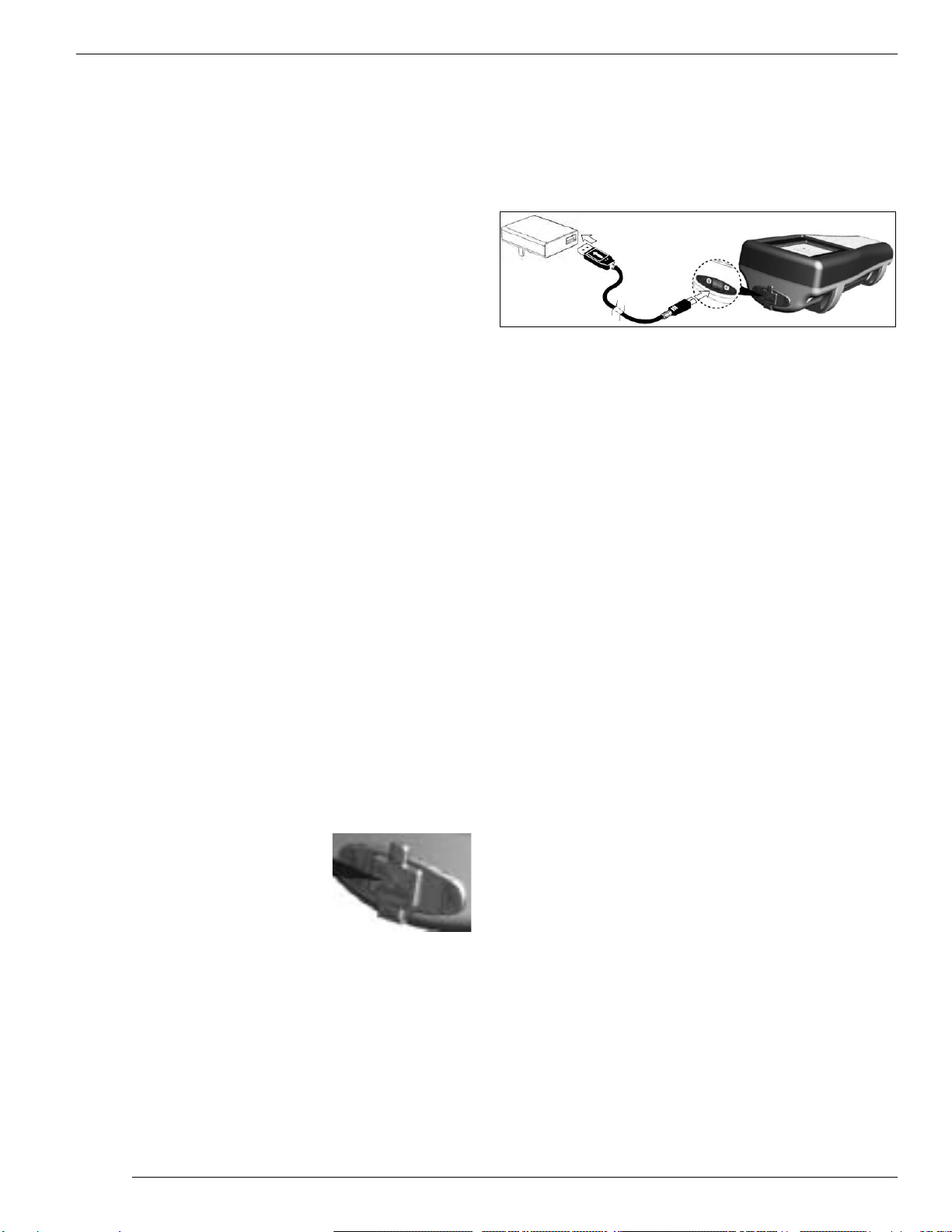
Retrieving from computer upload: Connect the
meter via its USB cable to a computer with
KorDSS software loaded, and open KorDSS.
Wait for the data in the meter to upload
automatically. Then, on the Home Screen,
choose “View Logged Data” and “Search.”
Choose your search criteria, then in the Results
screen, select the datasets you want to view,
and hit “Accept.” Go to “Dashboard” tab and
view and record your readings. (You may have
to convert units in some cases, due to glitches
in the KorDSS software.) You can Print these
data sets or upload them to a .csv file. To find
other data sets, choose “Search” again.
Storage for >1 week
Use expired pH 4 buffer as a storage solution to
improve the life of the pH probe. Pour enough
pH 4 buffer in the calibration cup so the ends of
the sensor modules are all submerged when the
sensor assembly is oriented with the sensor
ends down. Store the unit in this orientation.

YSI ProDSS
Field Procedures 6 18th Edition, 2016
ProDSS Settings & Troubleshooting
Sensor, port plug, guard installation
Perform sensor/port plug installation in a clean,
dry environment; do not install in the field!
The ports on the ProDSS bulkhead are
universal; therefore, you can install any sensor
into any port. For highest accuracy, always
install a conductivity/temperature sensor to
compensate all measurement data for
temperature and dissolved oxygen data for
conductivity.
Before installing a sensor or port plug,
make sure that the sensor and
bulkhead
connectors are clean and dry.
If there is an
empty “slot” with no sensor or port plug
installed,
a port plug or sensor must be
installed or the bulkhead will be
damaged!
Equipment needed for sensor/port plug
installation:
•Sensor(s) and or port plug(s)
•Bulkhead
•Krytox or silicone o-ring lubricant
•Sensor installation/removal tool
•Lint-free cloth
Sensor Installation
1. Inspect the bulkhead port for contamination.
If the port is wet, carefully dry with a lint-
free cloth.
2. Apply a thin coat of lubricant to the sensor
o-rings. Wipe off any excess lubricant with a
lint-free cloth.
3. Carefully align the sensor and bulkhead
connectors by inserting the sensor into the
port and then gently rotating the sensor
until the connectors align. Once aligned,
push the sensor toward the bulkhead until
the sensor seats in the port.
4. Carefully finger-tighten the retaining nut
clockwise. NOTE: If any resistance is felt,
loosen the retaining nut completely to
prevent cross-threading. Incorrect
installation may cause damage to the sensor
or bulkhead that is not covered by the
warranty.
5. Use the sensor installation/removal tool
to tighten the retaining nut clockwise until
snug, about a ¼ to ½ additional turn of the
retaining nut. NOTE: Do not over-tighten
the retaining nut. Over-tightening can cause
damage to the sensor or bulkhead not
covered by the warranty.
Port Plug Installation
If there is an empty slot in the bulkhead, install
a port plug.
Never submerge the bulkhead

YSI ProDSS
Field Procedures 7 18th Edition, 2016
without a sensor or port plug installed in
all ports!
1. Apply a thin coat of lubricant to the o-rings
on the plug port. Wipe off any excess
lubricant with a lint-free cloth.
2. Insert the port plug into the empty port and
press until firmly seated.
3. Finger-tighten the port plug clockwise to
install. If necessary, use the sensor
installation tool to make sure that the plug is
fully seated into the port.
NOTE: The o-rings will not be visible if a
port plug is correctly installed. Do not over-
tighten the port plug; over-tightening can
cause damage to the port plug or bulkhead
not covered by the warranty.
Sensor Guard Installation
Without the sensor guard, the sensors are
extremely vulnerable to environmental damage.
1. Carefully slide the sensor guard over the
sensors and bulkhead. Push the sensor
guard toward the bulkhead until the sensor
guard threads align with the bulkhead
threads.
2. Carefully finger-tighten the sensor guard
clockwise.
NOTE:
If any resistance is felt, loosen the
sensor guard completely to prevent cross-
threading. Incorrect installation may cause
damage to the sensor guard or bulkhead that is
not covered by the warranty.
USB port cleaning
If the USB port cover gets
dislodged, dirt can get into
the port area. However, the
port entry is waterproof even when the port is
exposed. To clean dirt from the port area:
•Flush the port area out with water.
•Pour isopropyl alcohol into the port area
and let it sit for 30 seconds.
•Pour out the alcohol and let dry before
replacing the port cover.
Battery pack troubleshooting
If the instrument is not turning on, do the
following:
1. Attempt to charge the unit: Using YSI
charging equipment only, plug unit into
the AC adapter with the USB connector
(see figure on next page).
2. If this does not power on the unit,
remove battery pack cover and examine
battery pack (see figure on previous
page).
NOTE: Do not remove the battery pack
if it is hot to the touch, is producing an
odd odor, or is leaking a fluid.
Removing and examining the battery pack
needs to be done with extreme care by a
team leader and in a dry, clean place,
preferably not in the field!
a) Remove the battery pack cover by
unscrewing (counter-clockwise) the
four screws with a flat or Phillips
head screwdriver (the retaining
screws are captured into the cover
and are not removable).
b) Inspect the battery pack; make sure
the battery pack connector is
properly connected to the
instrument.
c) If the connectors do not appear to
be properly connected, grasp the
battery pack connector with two
fingers and pull the connector
straight up to disconnect and
remove. Inspect the connector and
instrument pin connectors for any
debris or damage. If the connectors
look OK, align the battery pack
connector wire terminals with the
three instrument pins and connect
the battery pack.
d) If connectors look properly
connected, reinstall the battery

YSI ProDSS
Field Procedures 8 18th Edition, 2016
cover and attempt to charge the unit
again. If the unit still will not turn
on, the battery pack may need to be
replaced. (Before ordering a new
battery pack, call YSI at
800.765.4974 and troubleshoot
problems with a ProDSS tech.)
e) If a new battery pack has been
ordered, refer to the YSI manual for
battery removal/disposal and
replacement.
System settings
Date/Time
If the date and time are inaccurate, press the
system button
, go to the Date/Time
submenu option, scroll down to Date and hit
Enter. In the numeric entry screen, use the
arrow keys to maneuver around. If entire date
needs to be corrected, click the
delete entire
entry
key
. If not, use the
backspace key
to partially correct the date. After
correcting the date, hit Enter. Scroll down to
Time and hit Enter, then follow similar
instructions as for date correction to correct the
time. When finished, hit the Esc. or left arrow
button until you are back to the Run screen.
Logging Data
If the logging settings are inaccurate, press the
system button , scroll down to the logging
submenu option, go to the Continuous Mode,
and uncheck the box by pressing Enter. The
box should become unchecked . Press the
Esc button to return the Run Screen. In the
green bar at the top of the screen it should now
read “Log One Sample”.
Sensor Display Details
If there is a parameter not displayed on the
Run Screen, either the sensor is not installed
correctly, or it is not working properly. To
check if the sensor is installed properly, refer to
the above section on Sensor, Port Plug,
Guard Installation and carefully examine the
sensors.
If the units do not match on the Run Screen, go
to the
probe button
and scroll down to
Display submenu and hit Enter. Scroll down
and select the desired parameter. A submenu
will appear with multiple parameter unit
options; select the proper unit (see protocol
above) and return to the Run Screen.
Cleaning the bulkhead & probes
The bulkhead, probe guard, and calibration cup
can all be cleaned with a mild detergent. A
bottle brush works well for cleaning the
calibration cup; remove the locking ring and
gasket and scrub the inside of the chamber
well. Remove the bottom of the cup to clean it
as well, particularly the threads which can get
full of grit. Use a bottle brush to clean the
probe guard, removing it from the bulkhead
and unscrewing the bottom of the guard to
clean it. Clean any dirt off of the bulkhead and
sides of the probes using a toothbrush. Don’t
scrub the faces of the probes with a brush, as
this could cause damage. Be sure to rinse
everything well with tap water after you’ve
cleaned it.
Other manuals for ProDSS
6
Table of contents
Other YSI Multimeter manuals