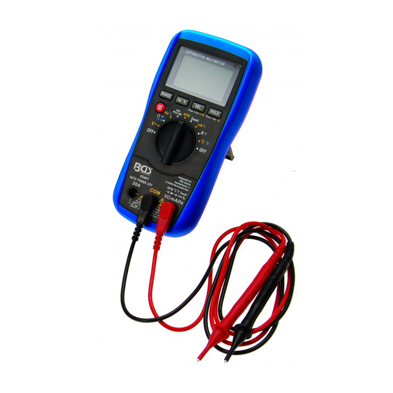
BGS technic 63402 User manual

SW-Stahl und Werkzeugvertriebs GmbH Tel. +49 (0) 2191 / 46438-0
F56essartSresukreveL ax +49 (0) 2191 / 46438-40
ed.lhatsws@ofni:liaM-EdiehcsmeR79824-D
Instruction Manual
BGS technic KG
Bandwirkerstr. 3
42929 Wermelskirchen
Tel.: 02196 720480
Fax.: 02196 7204820
www.bgstechnic.com
© BGS technic KG, Copying and further use not allowed
Art. 63402
Digital Multimeter
INTRODUCTION
The instrument of this series is a small hand-held 3 1/2 digital multimeter feature stable, highly reliable
and anti-drop performance. It is provided with a LCD display of 15 mm height for clear reading.
The circuit design takes LSI double integral A/D converter as its core under the protection of an
overload protection circuit, making it a superior and handy instrument.
It can be used to measure DC and AC voltage, DC current, resistance and diodes test.
SAFETY INFORMATION
This meter has been designed according to IEC 61010 concerning electronic measuring instruments
with a measurement category (CAT II 600V) and pollution degree 2.
Warning
To avoid possible electric shock or personal injury, follow these guidelines:
Do not use the meter if it is damaged. Before you use the meter, inspect the case. Pay particular
attention to the insulation surrounding the connectors.
Inspect the test leads for damaged insulation or exposed metal. Check the test leads for
continuity. Replace damaged test leads before you use the meter.
Do not use the meter if it operates abnormally. Protection may be impaired. When in doubt, have
the meter serviced.
Do not operate the meter around explosive gas, vapor or dust.
Do not apply more than the rated voltage. As marked on the meter, between terminals or between
any terminal and earth ground.
Before use, verify the meter's operation by measuring a known voltage.
When measuring current, turn off circuit power before connecting the meter in the circuit.
Remember to place the meter in series with the circuit.
When servicing the meter, use only specified replacement parts.
Use caution when working with voltage above 30V ac rms, 42V peak, or 60V dc. Such voltages
pose a shock hazard.
When using the probes, keep your fingers behind the finger guards on the probes.
When making connections, connect the common test lead before you connect the live test lead.
When you disconnect test leads, disconnect the live test lead first.
Remove the test leads from the meter before you open the battery cover or the case.
Do not operate the meter with the battery cover or portions of the case removed or loosened.

SW-Stahl und Werkzeugvertriebs GmbH Tel. +49 (0) 2191 / 46438-0
F56essartSresukreveL ax +49 (0) 2191 / 46438-40
ed.lhatsws@ofni:liaM-EdiehcsmeR79824-D
Instruction Manual
BGS technic KG
Bandwirkerstr. 3
42929 Wermelskirchen
Tel.: 02196 720480
Fax.: 02196 7204820
www.bgstechnic.com
© BGS technic KG, Copying and further use not allowed
To avoid false readings, which could lead to possible electric shock or personal injury, replace the
battery as soon as the low battery indicator ( ) appears.
Do not use the meter in a manner not specified by this manual or the safety features provided by
the meter may be impaired.
When in Data Hold mode, the symbol ( ) is displayed. Caution must be used because
hazardous voltage may be present.
To avoid electric shock, do not touch any naked conductor with your hand or skin, and do not
ground yourself while using the meter.
Comply with local and national safety requirements when you work in hazardous locations. Use
correct protective equipment, as required by local or national authorities, when you work in
hazardous areas.
When an input terminal is connected to dangerous live potential, it is to be noted that this potential
can occur at all other terminals!
CAT II - Measurement Category II is for measurements on all domestic appliances with plug
connection and measurements on electrical circuit in automotive and motorcycle sector like fuses,
wiring, fuse boxes, switches, etc. Do not use the meter for measurements within measurement
Categories III or higher. Do not use the meter for measurement on distribution boards, circuit
breakers, wiring, including cables, bus-bars, junction boxes, switches, socket outlets in the fixed
building installation.
Caution
To avoid possible damage to the meter or to the equipment under test, follow these guidelines:
Disconnect circuit power and discharge all capacitors before testing resistance, diode, continuity
and temperature.
Use the proper terminals, function and range for your measurements.
Before measuring current and temperature, check the meter's fuse and turn off the power to the
circuit before connecting the meter to the circuit.
Before rotating the rotary switch to change functions, disconnect test leads from the circuit under
test.
Remove test leads from the meter before opening the meter case or the battery cover.
If the display shows a "1", this means that the selected measuring range is chosen too small, e.g.
if you choose the 200V measuring range the applied voltage is over 200V.
ELECTRICAL SYMBOLS
Alternating Current
Direct Current
Both direct and alternating current
Caution, risk of danger, refer to the operating manual before use.
Caution, risk of electric shock.
Earth (ground) Terminal
Fuse
Conform to European Union directives
The equipment is protected throughout by double insulation or reinforced
insulation.
SW-Stahl und Werkzeugvertriebs GmbH Tel. +49 (0) 2191 / 46438-0
F56essartSresukreveL ax +49 (0) 2191 / 46438-40
ed.lhatsws@ofni:liaM-EdiehcsmeR79824-D
Instruction Manual
BGS technic KG
Bandwirkerstr. 3
42929 Wermelskirchen
Tel.: 02196 720480
Fax.: 02196 7204820
www.bgstechnic.com
© BGS technic KG, Copying and further use not allowed
FRONT PANEL
1 Display 3 1/2 digital 15 mm height, 7 sections LED display
2
Function /
Range
Switch
Used to select the desired function or range as well as to turn on or off the
meter. To preserve battery life, set this switch to OFF position when the meter
is not in use.
3 VΩmA
Terminal Plug-in connector for the red test lead for most measurements.
4 COM
Terminal Plug-in connector for the black test lead for all measurements.
5 10A
Terminal Plug-in connector for red test lead for current 200 mA to 10 A measurements.
6 HOLD
Button
Press the HOLD button. The LED will hold the last reading measured and
display the Hsymbol. When the button is released, the instrument will return to
normal mode.

SW-Stahl und Werkzeugvertriebs GmbH Tel. +49 (0) 2191 / 46438-0
F56essartSresukreveL ax +49 (0) 2191 / 46438-40
ed.lhatsws@ofni:liaM-EdiehcsmeR79824-D
Instruction Manual
BGS technic KG
Bandwirkerstr. 3
42929 Wermelskirchen
Tel.: 02196 720480
Fax.: 02196 7204820
www.bgstechnic.com
© BGS technic KG, Copying and further use not allowed
MAINTENANCE
Before removing the rear cover, disconnect the probe from the circuit to be measured.
To protect the internal circuit, replace the fuse with one of the same specification.
Don't use the instrument until the rear cover is placed back and the screws are tightened.
Clean the housing of instrument only with a wet rag dripped with little detergent but never chemical
solution. In case of any abnormality, stop using it and sent it for maintenance.
TECHNICAL DATA
Accuracy: +% of reading 5 digits, one year warranty.
Max. Voltage between input and the ground:CAT III 600V / Protection Type: IP20 / Protection Class: II
Fuse: F1 250mA / 600V F2 10A / 600V Power: 9V NEDA 1604/1604A, IEC 6F22/6LR61
Over-range indication: "1" (input higher than range) Polarity display: " -" for negative polarity
Operating temperature: 0°C to 40°C Storage temperature: -10°C to 50°C
Ambient temperature: 18°C to 28°C Ambient humidity: 80%
Low voltage indication: " " on the display Maximum display value: 1999
Dimension: about 138 mm x 69 mm x 31 mm Weight: 170g
DC Voltage
Range
Resolution
Accuracy
200 mV 100 µV
±(0.5% +3)
2 V 1 mV
20 V 10 mV
200 V 100 mV
600 V 1 V ±(0.8% +5)
Overload protection: 200mV range: 250V DC or RMS; the rest ranges: 600 V DC or RMS
AC Voltage
Range
Resolution
Accuracy
200 V 100 mV ±(1.2% +10)
600 V 1 V
Overload protection: 600V DC or RMS, Frequency range: 40Hz to 400Hz
Display: Average (effective value of sinusoid)
DC Current
Range
Resolution
Accuracy
20 µA 0.01 µA
±(1.0% +3)
200 µA 0.1 µA
2 mA 1 µA
20 mA 10 µA
200 mA 100 µA
10 A 10 mA ±(3.0% +10)
Overload protection: F1: 250mA / 600V - Fuse F2: 10A / 600V
Resistor
Range
Resolution
Accuracy
200 Ω0.1 Ω
±(0.8% +2)
2 KΩ0.001 KΩ
20 KΩ0.01 KΩ
200 KΩ0.1 KΩ
2 MΩ0.001 MΩ±(1.0% +5)
Maximum open circuit voltage: 3.2V, Overload protection: 250V DC or RMS
Diode
Range
Description
The approx. forward voltage drop of the diode will be displayed.

SW-Stahl und Werkzeugvertriebs GmbH Tel. +49 (0) 2191 / 46438-0
F56essartSresukreveL ax +49 (0) 2191 / 46438-40
ed.lhatsws@ofni:liaM-EdiehcsmeR79824-D
Instruction Manual
BGS technic KG
Bandwirkerstr. 3
42929 Wermelskirchen
Tel.: 02196 720480
Fax.: 02196 7204820
www.bgstechnic.com
© BGS technic KG, Copying and further use not allowed
INSTRUCTIONS
Notices before operation:
1. Plug the instrument in, check the 9V battery, if it is low, the symbol will display, requiring
battery replacement; otherwise follow the steps below.
2. The besides the probe jack indicates that the input voltage or current should not exceed the
specified limits to protect the internal circuit.
3. Before measurement, turn the function / range switch to the desired range.
Direct current voltage measurement
Insert the red probe into the " VΩmA " jack and the black one
into the “ COM “ jack.
Turn the function / range switch to the V- range and connect the
probe to the power supply or load to be measured. The polarity
touched by the red probe will be shown on the display.
Notice
If you do not know the measured voltage range in advance, set
the function / range switch to the maximum range, and then
gradually turn to smaller ranges until satisfactory resolution.
If the display shows "1" this indicates an over-range
measurement, and the switch should be set to a higher range.
Do not input a voltage of more than 600V, it is capable of
indicating a higher voltage, but with the risk of damaging the
inside circuit.
When taking the measurement of high voltage, pay special
attention to avoid an electric shock.
Direct current measurement
Place the black probe into the “ COM “ jack, for current to be
measured not exceeding 200mA, put the red one into the " VΩmA "
jack. For current to be measured between 200mA and 10A, insert
the red probe into the “ 10A “ jack.
Set the function / range switch to desired Ampere range and
connect the probe in series with the load to be measured. The
current value and the polarity connected to the red probe will be
shown on the display.
If you do not know the measured voltage range In advance, set the
function/range switch to the maximum range, and then graduaIly
turn to smaller ranges until satisfactory resolution.
If the display shows " 1" this indicates an over-range
measurement, and the switch should be set for a higher range.
The symbol " " beside the probe indicates the maximum input
current is 200mA or 10A, depending on the inserted jack.
Over current will blow the fuse.
up to 200mA
200mA to 10A

SW-Stahl und Werkzeugvertriebs GmbH Tel. +49 (0) 2191 / 46438-0
F56essartSresukreveL ax +49 (0) 2191 / 46438-40
ed.lhatsws@ofni:liaM-EdiehcsmeR79824-D
Instruction Manual
BGS technic KG
Bandwirkerstr. 3
42929 Wermelskirchen
Tel.: 02196 720480
Fax.: 02196 7204820
www.bgstechnic.com
© BGS technic KG, Copying and further use not allowed
Alternating voltage measurement
Place the red probe into the “ VΩmA " jack and the black one
into the " COM " jack.
Turn the switch to V~ range and connect the probe to the power
supply or load to be measured.
Notice
If you do not know the measured voltage range in advance, set
the function / range switch to the maximum range, and then
gradually turn to smaller ranges until satisfactory resolution.
If the display shows " 1 " this indicates an over-range
measurement, and the switch should be set to a higher range.
Do not input a voltage of more than 600V, it is capable of
indicating a higher voltage, but with the risk of damaging the
inside circuit.
When taking the measurement of high voltage, pay special
attention to avoid an electric shock
Resistance measurement
Place the black probe into the “ COM “ jack and the red probe
into the “ VΩmA “ jack.
Turn the switch to Ωrange and connect the probe to the resistor
being measured and read the results on display.
Notice
If the resistor being measured is greater than the value of the
selected range, the display will shown “ 1“ requiring the
selection of a higher range. It normally takes a few seconds for
the reading to get stable when measuring a resistor larger than
1MΩ.
In default of input, for instance, open circuit,
the display shows " 1".
When measuring an online resistor, de-energized the circuit
being measured and discharge all capacitors.
Diode measurement
Insert the black probe into the “ COM “ socket and the red one
into the " VΩmA " jack, then the red probe will be of positive
polarity.
Turn the switch to the diode range, and connect the red probe to
the positive pole of the diode being measured and the black one
to the negative pole, read the approximate forward voltage drop
on the diode on the display.

SW-Stahl und Werkzeugvertriebs GmbH Tel. +49 (0) 2191 / 46438-0
F56essartSresukreveL ax +49 (0) 2191 / 46438-40
ed.lhatsws@ofni:liaM-EdiehcsmeR79824-D
Instruction Manual
BGS technic KG
Bandwirkerstr. 3
42929 Wermelskirchen
Tel.: 02196 720480
Fax.: 02196 7204820
www.bgstechnic.com
© BGS technic KG, Copying and further use not allowed
Replacement of battery and fuse
Under normal conditions, it is unnecessary to replace the fuse. Don't replace it until the probes are
unplugged and the power is shut down. Take out the two screws of the rear cover to remove the
housing!
Warning
To avoid electric shock make sure the probes are disconnected
from the measured circuit before removing the rear cover.
Make sure the rear cover is tightly screwed before using the
instrument.
Don't put the instrument into use until the rear cover is screwed
after replacing battery or fuse.
The specification of the fuse is: F1 250mA / 600V and F2 10A /
600V. The replacement should be of the same specification.
The battery for this multimeter is 9V NEDA 1604 / 1604A, IEC
6F22 / 6LR61. The replacement should be of the same
specification.
Attachments
Instruction Manual
One pair of probe
9V battery NEDA 1604 / 1604A, IEC 6F22 / 6LR61
Note on the disposal of electrical equipment
Electrical appliances, electronic devices and Battery must not be
disposed of in the normal domestic waste. Instead, they are to be
delivered to dealer or the local collection points of the municipalities.

SW-Stahl und Werkzeugvertriebs GmbH Tel. +49 (0) 2191 / 46438-0
F56essartSresukreveL ax +49 (0) 2191 / 46438-40
ed.lhatsws@ofni:liaM-EdiehcsmeR79824-D
CE-Erklärung
BGS technic KG
Bandwirkerstr. 3
42929 Wermelskirchen
Tel.: 02196 720480
Fax.: 02196 7204820
www.bgstechnic.com
EU-Konformitätserklärung
EC DECLARATION OF CONFORMITY
DÉCLARATION „CE“ DE CONFORMITE
DECLARATION DE CONFORMIDAD UE
Wir erklären in alleiniger Verantwortung, dass die Bauart der:
We declare that the following designated product:
Nous déclarons sous propre responsabilité que ce produit:
Declaramos bajo nuestra sola responsabilidad que este producto
Digital-Multimeter ( BGS Art. 63402 )
Digital Multimeter
Multimètre Numériques Digital
Multimetro Digital
folgenden einschlägigen Bestimmungen entspricht:
complies with the requirements of the:
est en conformité avec les réglementations ci-dessous:
esta conforme a las normas:
EMC Council Directive 2014/30/EU
LVD Council Directive 2014/35/EU
Angewandte Normen:
Identification of regulations/standards:
Norme appliquée:
Normas aplicadas:
EN 61326-1:2013
EN 61326-2-2:2013
EN 61010-1:2010
EN 61010-2-030:2010
EN 61010-2-033:2012
Attestation: E8A 150354539006 / MAS830B
Test Report No: 64760140439101
Attestation: N5A 150354539005
Test Report No: 64240140439101
Wermelskirchen, den 19.05.2015
ppa.
Frank Schottke, Prokurist
BGS technic KG, Bandwirkerstrasse 3, D-42929 Wermelskirchen
Other manuals for 63402
1
Table of contents
Other BGS technic Multimeter manuals

BGS technic
BGS technic 2200 User manual

BGS technic
BGS technic 8890 User manual

BGS technic
BGS technic 2202 User manual

BGS technic
BGS technic 9074 User manual

BGS technic
BGS technic 63400 User manual

BGS technic
BGS technic 63401 User manual

BGS technic
BGS technic 2182 User manual

BGS technic
BGS technic 63402 User manual

BGS technic
BGS technic 2203 User manual

BGS technic
BGS technic 63400 User manual