Sunergy SUN330-72M Service manual

SUNERGY USA WORKS LLC
1
INSTALLATION INSTRUCTION MANUAL
CRYSTALLINE PV MODULE
1. INTROUDUCTION
SUNERGY USAWORKS LLC is a high-tech company engaged in development, research, production,
sales, and service of solar panels, and photovoltaic systems.
SUNERGY USA WORKS LLC supply products to more than 60 countries and regions on five
continents, such as Germany, Spain, Italy, America, Canada, Korea, Japan, and China and so on. Our
solar panels are widely used in commercial, residential and industrial solar power system
(on-grid&off-grid), PV power station and many other different regions.
SUNERGY USA WORKS LLC is located in 1330 St.Mary's Street, Ste.330, Raleign, NC, 27605,
WAKE, USA
1.1 POWER MODULE
SUNERGY USA WORKS LLC Solar Photovoltaic modules consist of a series of electrically
interconnected crystalline silicon solar cells. Which are permanently encapsulated between a
tempered glass superstrate and substrate. The entire laminate is secured within an anodized
aluminum frame for structural strength; ease of installation and to protect the cells from the most
severe environmental conditions.
1.2 Label
Each module hasa label on its rear side providing the following information:the product type, rated
power, rated current, rated voltage, open circuit voltage, short circuit current, all as measured
under standard test conditions, and weight, dimension, the maximum system voltage, maximum
fuse rating and so on.
Each module has only one bar code as shown below:

SUNERGY USA WORKS LLC
2
1. APPLICATIONS
SUNERGYSolar PV modules are a highly reliable, virtually maintenance-free direct current (DC)
power source, designed to operate most efficiently in sunlight. SUNERGY seriesmodules are ideal
to power remote homes, recreational vehicles, water pumps, telecommunications systems and
manyother applications either with or without the use of storage batteries. ClassA, Modules rated
for use inthis application class may be used in systems operating at greater than 50V DC or 240W,
where general contact access is anticipated. Modules qualified for safety through this part of IEC
61730-1 and IEC 61730-2 and within this application class are considered to meet the
requirements for safety class II.
Notes: The recommended maximum series/parallel module configurations are as follow:
72 6 " mono series: 16/1 60 6 " mono series: 20/1
54 6 " mono series: 21/1 36 6 " mono series: 32/1
72 6 " poly series: 17/1 60 6 " mono poly: 20/1
54 6 " poly series: 23/1 36 6 " mono poly: 34/1
2. PERMIT
Before installing your system, contact local authorities to determine the necessary permit,
installation and inspection requirements.
3. CLIMATE CONDITION
Install the SUNERGYSolar crystalline series modules in the following conditions:
Ambient temperature: -20°C to + 40°C
Operating temperature: -40°C to +85°C
Storage temperature: -40°C to +40°C
Humidity: below85RH%
Wind pressure: below 50.12Ib / ft2(2400Pa)
Corrosion resistance: Except for corrosive salt area and sulfurous area.
4. WARNING AND NOTES FOR SAFE INSTALLATION WORK
This system shall be installed only by engineers who have completed the training course.
Each solar panel has a junction box, can provide cable according to customer’s requirement.

SUNERGY USA WORKS LLC
3
Installers must know the possible danger of death or serious bodily injury.
Do not cut the connection wire under the loading.
Do not modify solar panel, move any labels or other parts.
Do not use chemicals on solar panel surfaces.
Do not expose solar panels to sunlight that is concentrated with mirrors, lenses or similar means.
Solar panel installation must obey the local law, even it should get the Construction Licence.
Do not wear the things, such as rings, metal jewelry, diamond jewelry or tools. which can damage
the surface of module during the installation process.
5. SAFETY REGULATOINS REGARDING INSTALLATION OF SOLAR POWER SYSTEMS
6.1 Take the following precautions before starting work
Plan the job and visit the site before starting work. On site, do not work along. Always work with at
least one other person. Inspect power tools before using them
6.2 Observe safety regulations during installation
Do not wear metallic jewelry, which may cause electrical shock
Keep the back side of solar panel surfaces free of foreign objects
Completely cover solar panel with opaque materials when wiring to halt productions of electricity.
6. REQUIRED INFORMATION
Artificially concentrated sunlight shall not be directed on the panel.
“Rated electrical characteristics are within 10 percent of measured values at Standard Test
Conditions of: 1000 W/m², 25 °C cell temperature and solar spectral irradiance per ASTME
892 or irradiation of AM 1.5 spectrum.
Under normal conditions, a photovoltaic panel may experience conditions that produce
more current and/or voltage than reported at Standard Test Conditions. Accordingly, the
values of Isc and Voc marked on should be multiplied by a factor of 1.25 when determining
component voltage ratings, conductor capacities, fuse sizes and size of controls connected
to the panel output. Refer to Section 690-8 of the National Electric Code for an additional
multiplying factor of 1.25 which maybe applicable.
8. POINTS TO CHECK WHEN SELECTING THE INSTALLATION LOCATION
8.1 The direction toward the equator to install solar modules, if possible. Installations facing
east and west are also possible, although the amount of power generated will be lower.
8.2 Install in a location that has good sun exposure throughout the year. Less power is
generated in shaded locations.
8.3 The output of a series string of solar panels is connected to the input of the inverter.
Always install solar panels so that all elements of the array receive the same amount of
sunlight.
8.4 It may not be possible to install solar panels in regions where maximum snow accumulation
exceeds the maximum allowable load.
9. MOUNTING AND NOTES
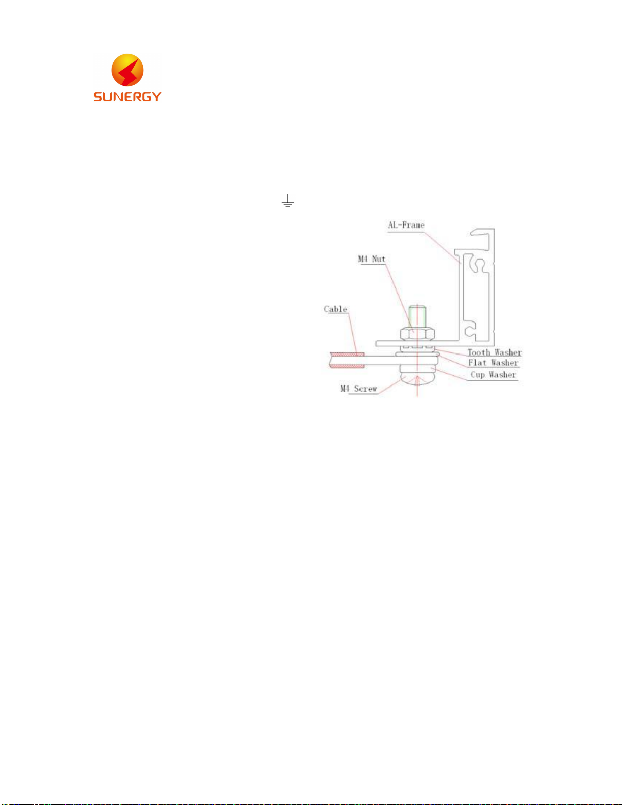
The module frame is made of anodized aluminum, and therefore corrosion can occur if the
modules is subject to a salt water environment with contact to a rack of another type of
metal (Electrolysis Corrosion). If required, PVC or stainless steel washers can be placed

SUNERGY USA WORKS LLC
4
between the module frame and support structure to prevent this type of corrosion. Module
support structures that are to be used to support modules at correct tilt angles should be
wind and snow load rated for use by the appropriate local and civil codes prior to
installation.
SUNERGYmodules can be mounted as following method:
Using corrosion-proof screws (M8) on the existing installing holes in the module frame.
The frame of each module has 8 mounting holes (12mm*9mm) used to secure the modules
to supporting structure. The module frame must be attached to a supporting structure using
M8 stainless steel hardware together with spring washers and flat washers in eight places
symmetrical on the SUNERGYmodule. The applied torque is about 8 Newton-meters.
The module can’t be installed using clamps.
It is not permitted to modify the module frame under any circumstances. Recommended
distance between 2 solar modules is 5mm considering linear thermal expansion of the
module frames. Clearance between the module frame and mounting surface may be
required to prevent the junction box from touching the surface, and to circulate cooling air
around the back of the module.
10. GROUNDING
All module frames and mounting racks must be properly grounded in accordance with the
appropriate respective national electrical code. Proper grounding is achieved by connecting the
module frame(s) and structural members contiguously one to another using a suitable grounding

SUNERGY USA WORKS LLC
5
conductor. The grounding conductor or strap may be copper, copper alloy, or other material
acceptable for use as an electrical conductor per respective National Electrical Codes. The
grounding conductor must then make a connection to earth using a suitable earth ground
electrode.
Attach a separate conductor as grounding wire to one
of the 4mm diameter grounding marked
on the module frame with a set of M4 screw, cup washer,
flat washer, tooth washer, and M4 nut. This is to ensure
positive electrical contact with the frame.
Schematic drawing
for SPV module grounding
11. INSTALLATION WORK
Using corrosion-proof screws (M8) on the existing installing holes in the module frame.
11.1 Secure the supporting structure according to the mounting holes in the frame of each
module.
11.2 The module frame must be attached to a supporting structure using M8 stainless steel
hardware together with spring washers and flat washers in eight places symmetrical on
the module.
11.3 Clearance between the module frame and mounting surface may be required to prevent
the junction box from touching the surface, and to circulate cooling air around the back
of the module.
11.4 Connecting the solar panels.
12. Connect each array according to the solar array connection examples.
12.1 The cable must not be bent or crushed on the direct exit of the cable screw joint include
connecter and junction box. A minimum bending radius R≥4×cable diameter must be
maintained. The cable must be routed in a way that tensile stress on the conductor or
connections is prevented. The cable must meet EN 50618.
12.2 There is a cable (+) and a cable (-) on the rear side of each solar panel. Connect the
waterproof connectors on these cables, making sure to push the connectors all the way
in.

SUNERGY USA WORKS LLC
6
12.3 On the first solar panel, connect the positive home run cable to the positive array output
cable, and connect the negative cable to the positive cable of the second solar panel.
On the second solar panel, connect the negative cable to the positive cable of the third
solar panel. Continue until you have series connected the appropriate number of panels
for the desired voltage.
12.4 When you have made direct connections between the specified number of solar panels,
use a digital multimeter to measure the voltage and current output of the array.
12.5 Organize the cables between solar panels.
13. Daily maintenance instructions
13.1 Do not clean the modules without professional authorized, and ensure the appropriate facilities
to conduct security operations and aerial work with high-altitude awareness of the danger.
13.2 Checking the glass for cracks and damage before cleaning the module. If the modules have
been broken, do not be cleaned, and immediately inform the installer or maintainer.
13.3 Do not use cleaning components of a strong type of chemical or abrasive detergent and
disinfectant operations. To prevent serious pollution will reduce the output power. We
recommend using water to clean modules. If the animals that produce the dirt, a mild soapy
water and neutral disinfectant will be recommended. If necessary use a soft sponge or cloth to
wipe the modules, do not force or scratch the modules hard. Do not wear jewelry or watches
during cleaning the modules, Do not scraped off the dirt of animal from the components hard.
Over scratches cause power attenuation, and void your warranty policy. When the module of the
tilt angle is more than 15 degrees, the modules can self-clean naturally; when the component's
angle less than 15 degrees, regular cleaning is necessary. Regular inspection mounting bracket
corrosion or not, if we find evidence of corrosion, please consult installers; Regularly check the
integrity of the ground terminal, but do not try to change the electrical connection, if you suspect
a loose connection, please contact the installer.

SUNERGY USA WORKS LLC
7
Date sheet for all module types of the family
Product Electrical Ratings:
Module type SUN330-72
M
SUN335-72
M
SUN340-72
M
SUN345-72
M
SUN350-72
M
SUN355-72
M
Voc [V] /Tolerance 45.5±5% 45.90±5% 46.3±5% 46.9±5% 47.5±5% 47.7±5%
Vmp [V] 38.1 38.3 38.4 38.5 38.7 38.8
Isc [Adc] /Tolerance 9.24±5% 9.31±5% 9.35±5% 9.45±5% 9.53±5% 9.65±5%
Imp [Adc] 8.66 8.74 8.85 8.96 9.04 9.15
Pmp [W] /Tolerance 330±5% 335±5% 340±5% 345±5% 350±5% 355±5%
Maximum system voltage [V] 1000 1000 1000 1000 1000 1000
Maximum Over-Current
Protection Rating [A] 15 15 15 15 15 15
Module type SUN360-72
M
SUN365-72
M
SUN370-72
M
SUN275-60
M
SUN280-60
M
SUN285-60
M
Voc [V] /Tolerance 47.9±5% 48.1±5% 48.3±5% 38.0±5% 38.2±5% 38.7±5%
Vmp [V] 38.9 39.1 39.3 31.9 31.1 32.2
Isc [Adc] /Tolerance 9.75±5% 9.82±5% 9.85±5% 9.21±5% 9.35±5% 9.48±5%
Imp[Adc] 9.25 9.34 9.41 8.63 8.72 8.85
Pmp [W] /Tolerance 360±5% 365±5% 370±5% 275±5% 280±5% 285±5%
Maximum system voltage [V] 1000 1000 1000 1000 1000 1000
Maximum Over-Current
Protection Rating [A] 15 15 15 15 15 15

SUNERGY USA WORKS LLC
8
Module type SUN290-60
M
SUN295-60
M
SUN300-60
M
SUN305-60
M
SUN245-54
M
SUN250-54
M
Voc [V] /Tolerance 39.2±5% 39.6±5% 39.8±5% 40.1±5% 34.9±5% 35.3±5%
Vmp [V] 32.4 32.5 32.7 32.8 28.5 28.7
Isc [Adc] /Tolerance 9.58±5% 9.72±5% 9.78±5% 9.89±5% 9.14±5% 9.23±5%
Imp [Adc] 8.95 9.08 9.17 9.3 8.58 8.71
Pmp [W] /Tolerance 290±5% 295±5% 300±5% 305±5% 245±5% 250±5%
Maximum system voltage [V] 1000 1000 1000 1000 1000 1000
Maximum Over-Current
Protection Rating [A] 15 15 15 15 15 15
Module type SUN255-54
M
SUN260-54
M
SUN265-54
M
SUN270-54
M
SUN275-54
M
SUN165-36
M
Voc [V] /Tolerance 35.7±5% 36.2±5% 36.6±5% 36.9±5% 37.3±5% 23.1±5%
Vmp [V] 28.8 29.0 29.1 29.3 29.4 19.1
Isc [Adc] /Tolerance 9.35±5% 9.45±5% 9.6±5% 9.7±5% 9.81±5% 9.17±5%
Imp [Adc] 8.85 8.96 9.1 9.22 9.35 8.62
Pmp [W] /Tolerance 255±5% 260±5% 265±5% 270±5% 275±5% 165±5%
Maximum system voltage [V] 1000 1000 1000 1000 1000 1000
Maximum Over-Current
Protection Rating [A] 15 15 15 15 15 15
Module type SUN170-36
M
SUN175-36
M
SUN180-36
M
SUN185-36
M- -
Voc [V] /Tolerance 23.4±5% 23.8±5% 24.1±5% 24.5±5% - -
Vmp [V] 19.2 19.4 19.5 19.7 - -
Isc [Adc] /Tolerance 9.35±5% 9.53±5% 9.71±5% 9.85±5% - -
Imp[Adc] 8.85 9.04 9.23 9.39 - -
Pmp [W] /Tolerance 170±5% 175±5% 180±5% 185±5% - -
Maximum system voltage [V] 1000 1000 1000 1000 - -
Maximum Over-Current
Protection Rating [A] 15 15 15 15 - -

SUNERGY USA WORKS LLC
9
Product Electrical Ratings:
Module type SUN330-72P SUN325-72P SUN320-72P SUN315-72P SUN280-60P SUN275-60P
Voc [V] /Tolerance 45.50±5% 44.90±5% 44.60±5% 44.30±5% 38.50±5% 38.00±5%
Vmp [V] 37.80 37.70 37.50 37.30 9.29 31.40
Isc [Adc] /Tolerance 9.22±5% 9.10±5% 9.03±5% 8.93±5% 31.60±5% 9.18±5%
Imp [Adc] 8.73 8.62 8.53 8.44 8.86 8.76
Pmp [W] /Tolerance 330±5% 325±5% 320±5% 315±5% 280±5% 275±5%
Maximum system voltage [V] 1000 1000 1000 1000 1000 1000
Maximum Over-Current
Protection Rating [A] 15 15 15 15 15 15
Module type SUN270-60P SUN265-60P SUN250-54P SUN245-54P SUN240-54P SUN165-36P
Voc [V] /Tolerance 37.20±5% 37.00±5% 34.80±5% 34.30±5% 33.50±5% 23.00±5%
Vmp [V] 31.20 31.00 28.50 28.30 28.10 18.90
Isc [Adc] /Tolerance 9.06±5% 8.94±5% 9.19±5% 9.05±5% 8.95±5% 9.16±5%
Imp[Adc] 8.65 8.54 8.77 8.66 8.54 8.74
Pmp [W] /Tolerance 270±5% 265±5% 250±5% 245±5% 240±5% 165±5%
Maximum system voltage [V] 1000 1000 1000 1000 1000 1000
Maximum Over-Current
Protection Rating [A] 15 15 15 15 15 15
Module type SUN160-36P - - - - -
Voc [V] /Tolerance 22.30±5% - - - - -
Vmp [V] 18.80 - - - - -
Isc [Adc] /Tolerance 8.91±5% - - - - -
Imp [Adc] 8.51 - - - - -
Pmp [W] /Tolerance 160±5% - - - - -
Maximum system voltage [V] 1000 - - - - -
Maximum Over-Current
Protection Rating [A] 15 - - - - -

SUNERGY USA WORKS LLC
10
Temperature cofefficient
Temp. Cofe. Of Isc 0.048 % / °C
Temp. Cofe. Of Voc -0.30 % / °C
Temp. Cofe. Of Pmax -0.40 % / °C
This manual suits for next models
40
Table of contents