SKC 224-PCXR8M User manual

Operating Instructions
Universal Sample Pump
Catalog No. 224-PCXR8M
SKC Inc.
863 Valley View Road
Eighty Four, PA 15330
Form #37729 Rev 0804


Table of Contents
Description...........................................................................1
Performance Prole............................................................................................... 2
Operation..............................................................................4
High Flow Applications .......................................................................................... 4
Low Flow Single-tube Applications........................................................................ 9
Low Flow Multiple-tube Applications ................................................................... 14
Maintenance.......................................................................20
Pump Inlet Filter .................................................................................................. 20
Battery Pack Care ............................................................................................... 20
Replacing Battery Pack ....................................................................................... 21
Service Policy ....................................................................22
Parts Descriptions.............................................................24
Replacement Parts.............................................................................................. 26
Optional Accessories........................................................28
Warranty.............................................................................29
MSHA Approval .................................................................30
Indicates a warning or caution.
Indicates a premier feature of the pump.
Notice: This operating instruction may not address all safety concerns (if any) associated with this product and its use.
The user is responsible for determining and following the appropriate safety and health practices and regulatory limitations
(if any) before using the product. The information contained in this document should not be construed as legal advice,
opinion, or as a nal authority on legal or regulatory procedures.


1
Description
The PCXR8M Universal Sample Pump is a constant ow air sampler suitable for a broad
range of applications. It is ideal for industrial hygiene studies as well as environmental
testing.
Low Flow Regulator
(beneath cap screw)
allows pump to be switched
from high to low ow.
Durable RFI-shielded Case
provides protection from radio
frequency interference
between 27 and 1000 MHz.
Rechargeable NiCad Battery
provides continuous 8-hour
operation on a single charge.
Built-in
Particulate Trap
in see-through
housing
protects pump.
Built-in Rotameter
provides a visible check
of relative ow rate during
sampling from 0.5 to 3 L/min.
Accessory Mounting Screws
allow sampling accessories
such as impinger holders
to be secured to pump.
Recessed Flow Adjustment
adjusts ow rate between
1000 and 3000 ml/min.
Digital LCD
shows run time, set times,
battery check, and
fault functions.
Touch Keypad
for programmable
functions
On/Off Switch
Tamper-resistant Cover
prevents changes to settings.
PCXR8M Universal Sample Pump

2
Performance Prole
Flow Range: ......................... 1000 to 3000 ml/min
(5 to 500 ml/min requires adjustable low ow holder)
Weight: .................................. 34 oz (964 gm)
Dimensions: ........................ 5.1 x 4.7 x 1.9 in (13 x 11.9 x 4.8 cm)
Compensation Range: ....... 1000 ml/min at 40 inches water back pressure
2000 ml/min at 40 inches water back pressure
3000 ml/min at 22 inches water back pressure
Flow Control: ....................... Holds constant ow to ± 5% of the set point
Run Time: ............................. 8 hrs minimum at 3000 ml/min and 20 inches water back pressure;
dependent on media used
Flow Indicator: ..................... Built-in ow indicator with 250-ml division; scale marked at 1, 2, 3, 4,
and 5 L/min
Power Supply: .................... MSHA approved when used with rechargeable NiCad battery pack,
2.0-Ah capacity, 4.8 V, Cat. No. P22434 only. Recharge battery
pack in fresh air only.
Charging Time: .................... ≤ 6 hrs with PowerFlex Charger
Operating Temperature: .... -20 C to 45 C (-4 F to 113 F)
Storage Temperature: ........ -40 C to 45 C (-40 F to 113 F)
Charging Temperature: ..... 5 C to 45 C (41 F to 113 F)
Operating Humidity: .......... 0 to 95% Relative
Protect sample pump from exposure to water and weather.
Multiple-tube Sampling: ..... Built-in constant pressure regulator allows user to take up to four
simultaneous tube samples at different ow rates up to 500 ml/min
each (maximum total combined ow 1350 ml/min) using the adjust-
able low ow holder.
Flow and
Low Battery Fault: ............... If the pump is unable to compensate due to excessive back pres-
sure or if a low battery condition exists, the pump enters fault.
During fault, the pump shuts down, the LCD indicates a ow or low
battery fault, timing functions pause, and time display is retained.
Battery Test: ........................ LCD shows battery condition prior to sampling.
Time Display: ....................... LCD shows sampler run time in minutes for sampling period
elapsed time, pump run time, or total elapsed time including de-
layed start time.
3
Timing Accuracy: ............ ± 0.05% (± 45 seconds per day)
Sampling Pause: ............ Allows user to temporarily halt sampling without loss of timing data.
Restart does not require resetting time.
Timed Shutdown: ........... Allows user to select minutes of operation before automatic shutdown.
Timed shutdown maximum is 9999 minutes (7 days).
Delay On: ..........................
Allows user to select minutes to delay test up to 9999 minutes (7 days).
Intermittent Sampling: ... Programmable to allow user to extend short-term samples over an ex-
tended period of time to meet time weighted average (TWA) require-
ments with a reduced number of samples. Elapsed time maximum is
9999 minutes (7 days), at which time the sample pump shuts down.
RFI/EMI Shielding
Performance: ................ Complies with requirements of EN 55022, FCC Part 15 Class B, EN
50082-1; frequency range of the radiated susceptibility test was 27
MHz to 1000 MHz. CE marked.
Intrinsic Safety: ............... MSHA approved to 30 CFR, section 18; approval no. 2G-4036-0.
Tested for use in methane-air mixtures only.
Intrinsic safety and other approvals may be void if SKC pumps are not
repaired by SKC or authorized SKC repair centers.
Replacing parts with non-SKC parts or parts not approved for use with
this pump model can void intrinsic safety approvals and the manufacturer
warranty.
4
Operation
High Flow Applications (1000 to 3000 ml/min)
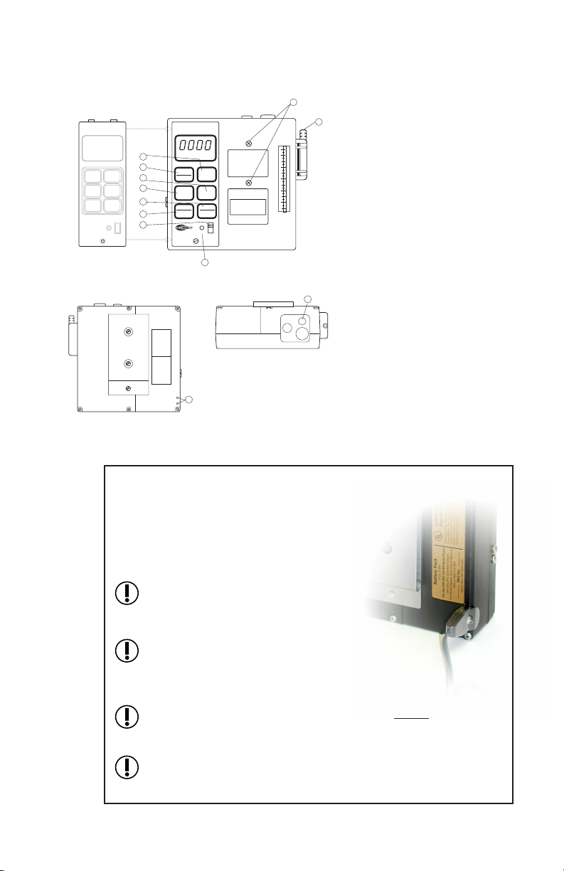
Setup
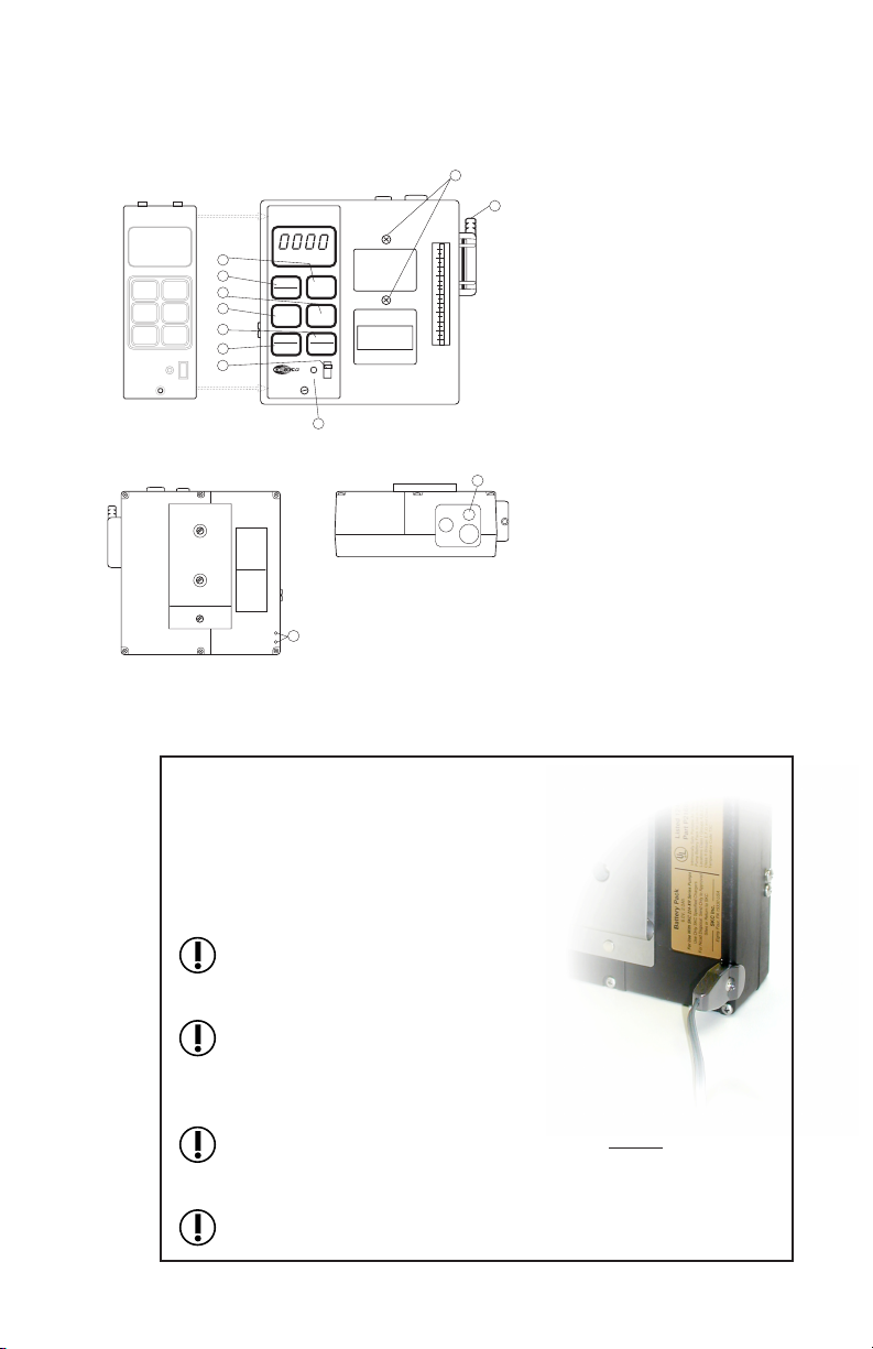
Ensure pump is not running. Charge the
battery by connecting the charger plug
to the sampler charging jack (Figure
1, #22). Ensure that the battery is fully
charged before sampling.
Do not charge or operate pump from
charger in hazardous locations.
Charge in fresh air only.
Use only an SKC-approved charger
designated for this model to ensure
reliable performance and to maintain
the SKC warranty.
Ensure proper orientation of charging cable before plugging it
into the charging jack. Improper orientation/contact will short-
circuit the battery.
Short-circuiting the battery pack will render it immediately
inoperative.
1
Charger and battery
pack connected
13
AIRCHEK
SAMPLER
5
4
3
2
1
SAMPLE PERIOD — MINUTES
START
HOLD
FLOW
AND
BATTERY
CHECK
DIGIT
SET
PUMP
RUN
TIME
DIGIT
SELECT
TOTAL
ELAPSED
TIME
SET-UP MODE
FLOW
ADJ
ON
AIRCHEK SAMPLER
MODEL 224-PCXR8M
11
22
18
BACK
TOP
FRONT
12
8
7
6
5
4
3
2
2 Flow and Battery Check Key
3 Start/Hold Key
4 Mode Key
5 Set-up Key
6 Digit Set/Pump Run Time Key
7 Digit Select/Total Elapsed
Time Key
8 On/Off Switch
11 Flow Adjust Screw
12 Accessory Mounting Screws (2)
13 Intake/Filter Housing
18 Cap Screw to Regulator
22 Charging Jack
Figure 1
Front, back, and top views of PCXR8M Sampler
For additional drawings, see pages 25 and 27.

5
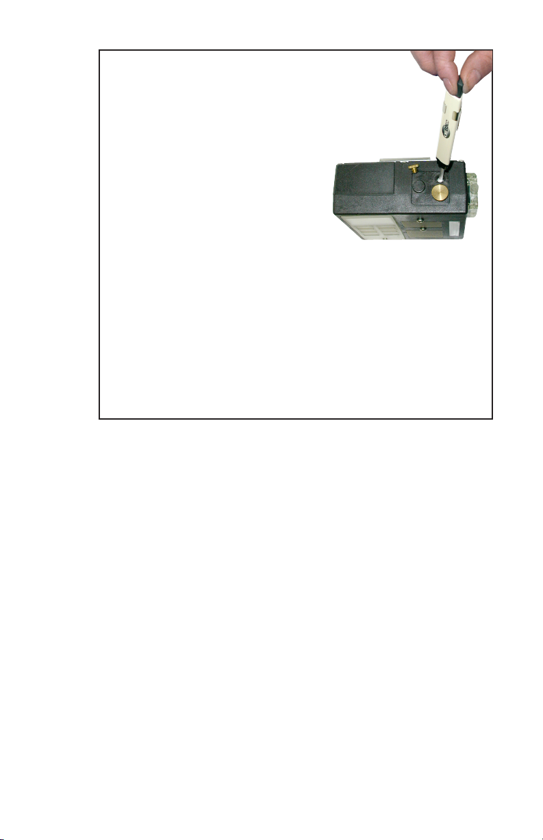
De-activating the Regulator
To ensure the pump is set for high ow,
remove the cap screw (Figure 1, #18)
covering the regulator valve and turn
the exposed screw clockwise until it
stops. (Do not overtighten.)
Replace the cap screw. The pump is
now set for high ow.
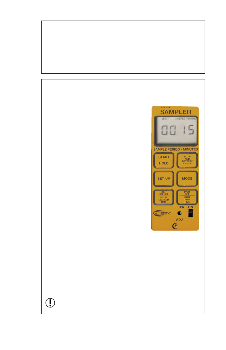
Setting or Verifying Flow Rate
Using 1/4-inch Tygon® tubing, connect the sampling medium to
the pump intake (Figure 1, #13).
Remove the tamper-resistant
cover. Start the pump
using the on/off switch
(Figure 1, #8). Press
Start/Hold (Figure 1, #3).
Press Flow and Battery
Check (Figure 1, #2).
Adjust the ow using the
ow adjust screw (Figure
1, #11) until the built-in
rotameter reads 2 L/min.
The LCD should indicate
BATT OK in the upper left cor-
ner (if it doesn’t, recharge the battery). Press Flow and Battery
Check to place the pump in Hold.
Connect a calibrator to the intake of the sampling medium.
Press Flow and Battery Check to start the pump, and set the ow
rate using the ow adjust screw (Figure 1, #11).
When the ow rate is set, press Flow and Battery Check to place
the pump in Hold. Disconnect the calibrator.
Replace the sampling medium used for calibration with unex-
posed medium for sample collection.
Calibration train with
lter cassette
2
3Flow
adjust
screw
On/Off
switch
Tubing
Calibrator
Sample
media
For high ow,
turn valve screw
clockwise.
6
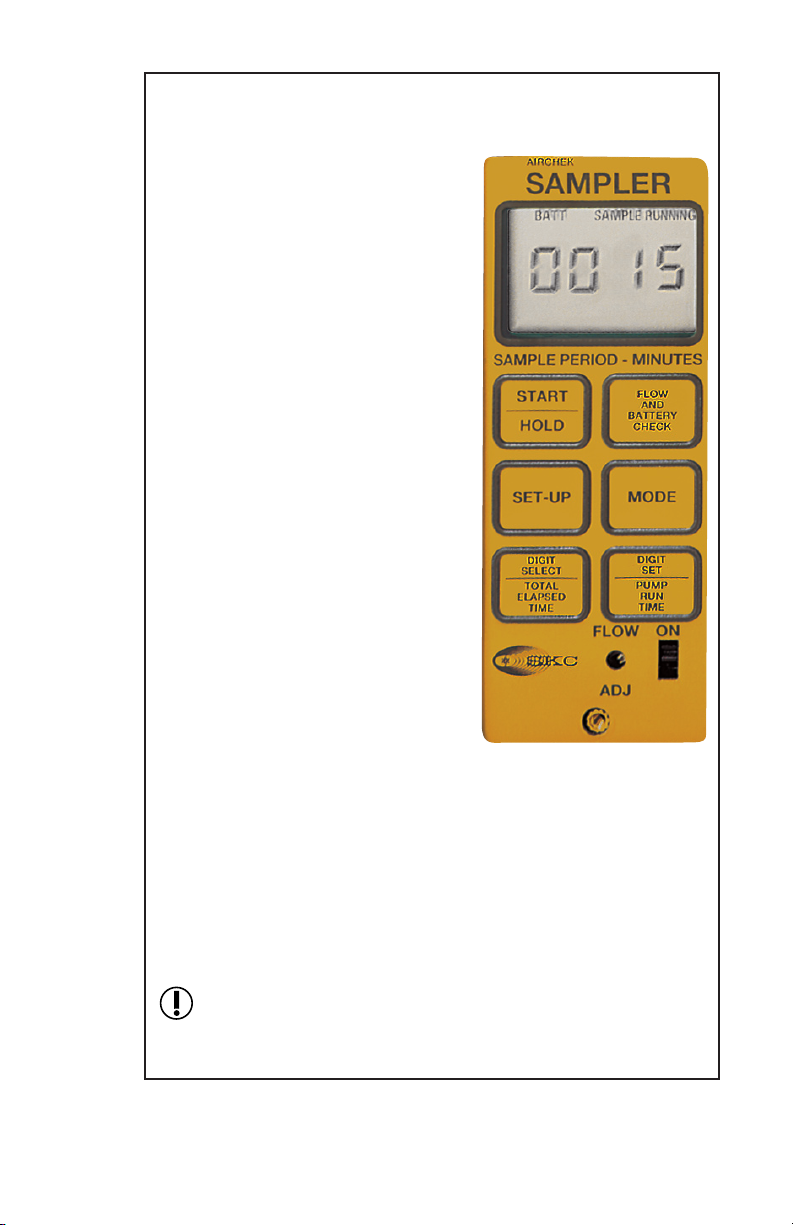
Programming Delayed and Intermittent
Sampling
To enter Delayed Start Mode:
From Hold, press Setup. Enter
the number of minutes delay (up
to 9999) before the sampling
period begins by pressing Digit
Select and Digit Set. Digit Select
advances the ashing digit and
Digit Set increases the value of the
ashing digit.
To enter Sample Period Mode:
Press Mode. Press Digit Select
and Digit Set to enter the sampling
time period in minutes (up to
9999). Note: The sample period is
the total period in which sampling
is performed and not the pump run
time.
To enter Pump Period Mode:
Press Mode. This is the actual run-
ning time of the pump. Use Digit
Select and Digit Set to enter the
pump run time in minutes (up to
9999).
If intermittent sampling is not
desired, set the sampling period
to equal the pump period. If the
pump running time is less than
the sampling period, the pump will automatically calculate and
control on/off cycling to complete the pump run time during the
sampling period.
Pressing Mode will scroll through the program sequence.
For intermittent sampling, the elapsed time maximum is 9999
minutes (7 days), at which time the sample pump will shut
down.
4
PCXR8M Keypad
7
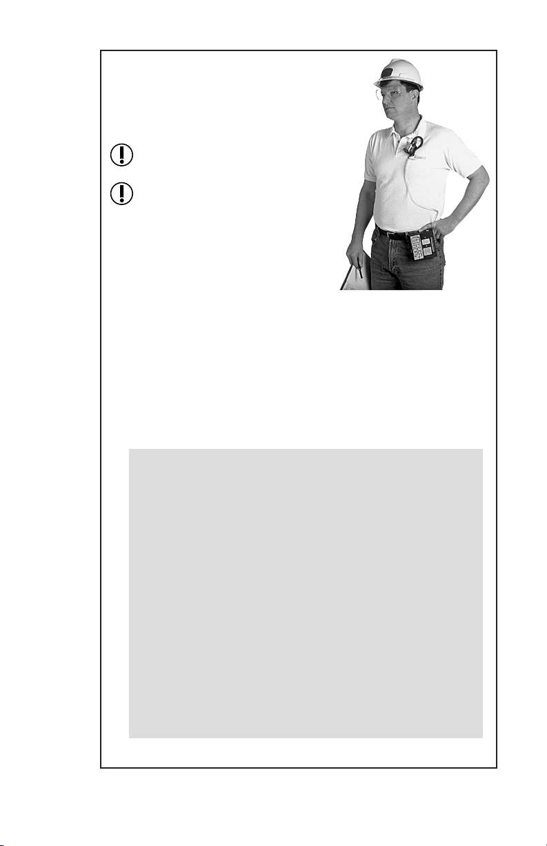
Sampling
For personal sampling, clip the sample
collection medium to the worker in the
breathing zone.
Protect sample pump from weather
when in use outdoors.
Use of any device other than the
approved battery pack to power
the pump voids MSHA approval.
While the LCD displays HOLD, start
sampling by pressing Start/Hold. If
a time delay has been programmed,
DELAYED START will ash on the
LCD and the amount of time remain-
ing until sampling starts will appear.
SAMPLE RUNNING will display when the delay sequence has
ended. The LCD will automatically track sampling period time
elapsed.
At the end of the sampling period, press Start/Hold and record
the stop time.
User Options During Sampling
Pause - Pause (shutdown) the pump by pressing Start/Hold. All
timing data will freeze. To resume sampling, press Start/Hold;
timing data will resume.
Flow or Battery Fault Shutdown - During restricted ow or
low battery conditions, the sampler will shut down. HOLD
will display on the LCD and timing functions will pause. LO
BATT or FLOW FAULT will display on the LCD depending
on the cause of the shutdown. To restart from ow fault, correct
the blockage and press Start/Hold. If LO BATT is displayed,
recharge the battery before sampling.
Display Times - Elapsed sampling period is continuously dis-
played on the LCD. Press and hold Pump Run Time (Figure
1, #6) to display pump run time. Press and hold Total Elapsed
Time (Figure 1, #7) to display total elapsed time, including
delayed start time.
Clip sample medium to
worker and pump to belt.
continued on page 8
5

8
Sampling with Impingers
When using impingers, place an
in-line trap between the pump and
the impinger to protect the sam-
pler from liquid or vapors. The
impinger and trap can be mounted
to the sampler using the accessory
mounting screws (Figure 1, #12) or
placed in a holster at the worker’s
waist.
Failure to use the impinger trap
voids the warranty.
Protect sample pump from
weather when in use outdoors.
Use of any device other than the approved battery pack
to power the pump voids MSHA approval.
Impinger holder on pump
with impinger and trap
5
(cont’d)
9
Setup
Ensure pump is not running. Charge the
battery by connecting the charger plug to the
sampler charging jack (Figure 1, #22). En-
sure that the battery is fully charged before
sampling.
Do not charge or operate pump from
charger in hazardous locations. Charge
in fresh air only.
Use only an SKC-approved charger
designated for this model to ensure
reliable performance and to maintain
the SKC warranty.
Ensure proper orientation of charging cable before plugging it
into the charging jack. Improper orientation/contact will short-
circuit the battery.
Short-circuiting the battery pack will render it immediately
inoperative.
1Charger and battery
pack connected
Low Flow Applications (5 to 500 ml/min)
Using Single Adjustable Low Flow Holder
13
AIRCHEK
SAMPLER
5
4
3
2
1
SAMPLE PERIOD — MINUTES
START
HOLD
FLOW
AND
BATTERY
CHECK
DIGIT
SET
PUMP
RUN
TIME
DIGIT
SELECT
TOTAL
ELAPSED
TIME
SET-UP MODE
FLOW
ADJ
ON
AIRCHEK SAMPLER
MODEL 224-PCXR8M
11
22
18
BACK
TOP
FRONT
12
8
7
6
5
4
3
2
2 Flow and Battery Check Key
3 Start/Hold Key
4 Mode Key
5 Setup Key
6 Digit Set/Pump Run Time Key
7 Digit Select/Total Elapsed
Time Key
8 On/Off Switch
11 Flow Adjust Screw
12 Accessory Mounting Screws (2)
13 Intake/Filter Housing
18 Cap Screw to Regulator
22 Charging Jack
Figure 1
Front, back, and top views of PCXR8M Sampler
For additional drawings, see pages 25 and 27.
10
Activating the Regulator
Remove the tamper-resistant
cover. Start the pump using the
on/off switch (Figure 1, #8). Press
Start/Hold (Figure 1, #3). Press
Flow and Battery Check (Figure
1, #2). Adjust the ow using the
ow adjust screw (Figure 1, #11)
until the built-in rotameter reads
1.5 L/min. The LCD should indi-
cate BATT OK in the upper left
corner (if it doesn’t, recharge the
battery). Press Flow and Battery
Check to place the pump in Hold.
Remove the cap screw covering the regulator valve (Figure 1,
#18) and turn the exposed screw four to ve turns counterclock-
wise.
Replace the cap screw. The pump is now set for low ow.
For low ow,
turn valve screw
counterclockwise.
2

11
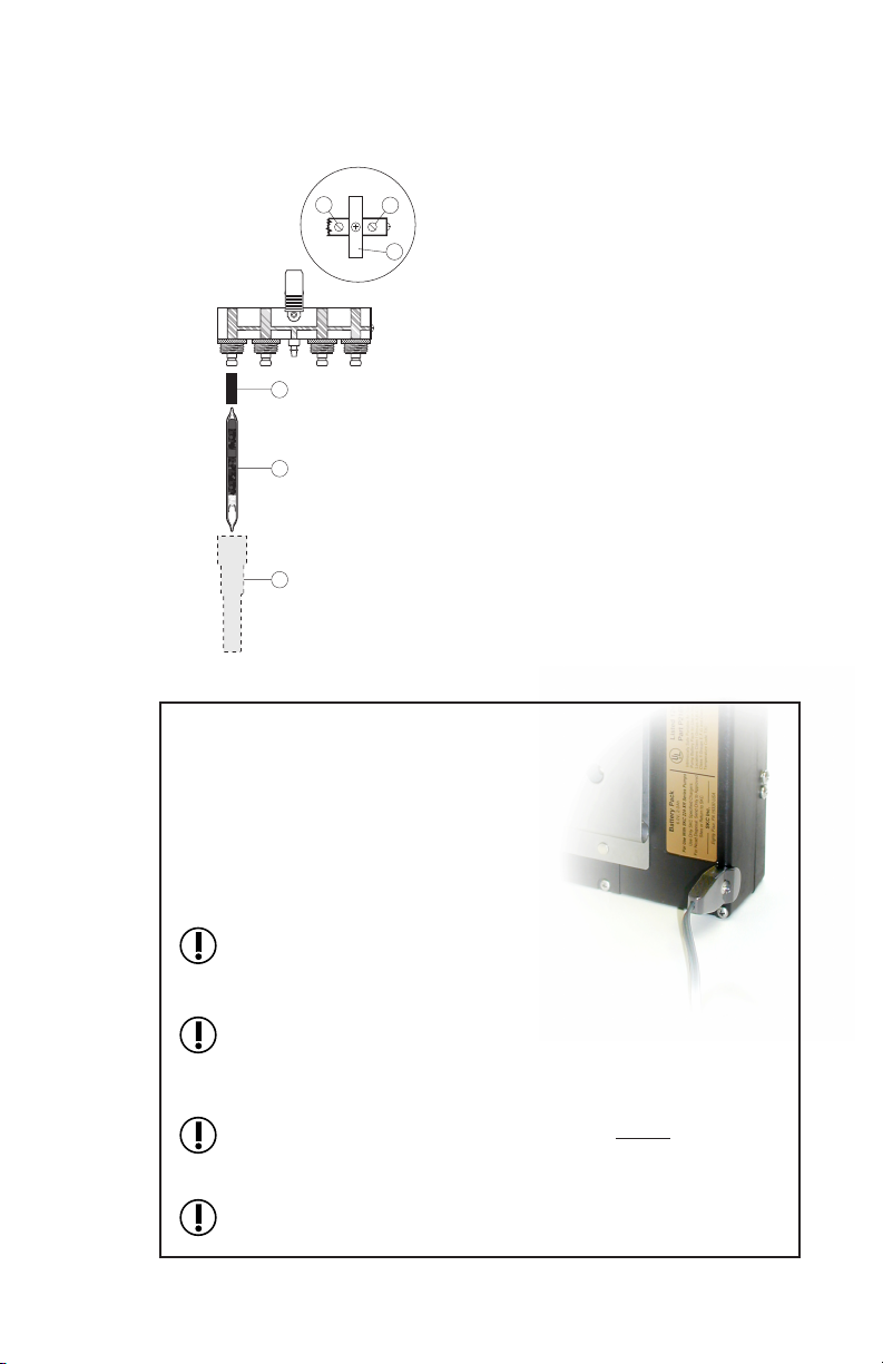
Figure 2
Single Adjustable
Low Flow Holder
with sample tube
1 Flow Adjust Screw
2 Rubber Sleeve
3 Sorbent Tube
Airow
Setting or Verifying Flow Rate
For a diagram of the pump, see Figure 1, page 9.
Connect a single adjustable low ow holder (Figure 2) to the
pump intake (Figure 1, #13) using 1/4-inch Tygon tubing.
Insert an opened sorbent tube
(Figure 2, #3) into the rubber
sleeve (Figure 2, #2) of the low
ow holder with the arrow on the
tube pointing toward the holder.
Connect a calibrator to the exposed
end of the sorbent tube.
Loosen the brass ow adjust screw on the low ow holder. Acti-
vate the pump by pressing Flow and Battery Check.
Adjust the ow rate by turning the
ow adjust screw (Figure 2, #1)
on the holder until the calibrator
indicates the desired ow.
Do not adjust the ow on the
pump. Adjust the ow only by us-
ing the ow adjust screw on the low
ow holder.
3Calibration train
with tube in low ow
holder
Turn screw on
low ow holder to
adjust ow.
Flow adjust
screw
continued on page 12
12
When the desired ow is set, place the pump in Hold by press-
ing Flow and Battery Check. Disconnect the calibrator. Replace
the sorbent tube used for setting the ow with a new unexposed
sorbent tube for sample collection.
Place the appropriate size tube cover over the tube, and screw it
into place on the low ow holder.
Programming Delayed and Intermittent
Sampling
To enter Delayed Start Mode: From
Hold, press Set-up. Enter the number
of minutes delay (up to 9999) before
the sampling period begins by pressing
Digit Select and Digit Set. Digit Select
advances the ashing digit and Digit Set
increases the value of the ashing digit.
To enter Sample Period Mode: Press
Mode. Press Digit Select and Digit Set to
enter the sampling time period in minutes
(up to 9999). Note: The sample period
is the total period in which sampling is
performed and not the pump run time.
To enter Pump Period Mode: Press
Mode. This is the actual running time of
the pump. Use Digit Select and Digit Set
to enter the pump run time in minutes (up
to 9999).
If intermittent sampling is not desired, set
the sampling period to equal the pump
period. If the pump running time is less
than the sampling period, the pump will automatically calculate
and control on/off cycling to complete the pump run time during
the sampling period.
Pressing Mode will scroll through the program sequence.
For intermittent sampling, the elapsed time maximum is 9999
minutes (7 days), at which time the sample pump will shut down.
4
PCXR8M Keypad
3
(cont’d)

13
Sampling
For personal sampling, clip the low ow
holder to the worker in the breathing zone.
Protect sample pump from weather when
in use outdoors.
Use of any device other than the approved
battery pack to power the pump voids
MSHA approval.
While the LCD displays HOLD, start sam-
pling by pressing Start/Hold. If a time delay
has been programmed, DELAYED START
will ash on the LCD and the amount of time remaining until
sampling starts will appear. SAMPLE RUNNING will display
when the delay sequence has ended. The LCD will automatically
track sampling period time elapsed.
At the end of the sampling period, press Start/Hold and record
the stop time.
To return to high ow, remove the low ow holder and
de-activate the regulator (see page 5).
For user options during sampling, see page 7.
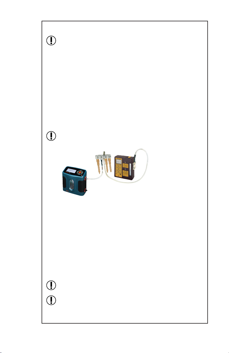
Sampling with Long-duration Color Detector Tubes
Long-duration Color Detector Tubes re-
quire a special tube cover that accommo-
dates an in-line trap tube. The trap tube
protects the pump from caustic fumes
which are often released from detector
tubes. Closely read all precautions when
using these tubes.
Failure to use the necessary traps
will damage the pump and void the
warranty.
Clip holder to worker
and pump to belt.
5
(See Optional Accessories, page 28)
Pump with
Tandem Tube
Cover
Long-duration
detector tube
Trap Tube
14
Low Flow Applications (5 to 500 ml/min)
Using Multiple-tube Adjustable Low Flow Holder
Figure 3
Quad Adjustable Low Flow Holder
1 Anti-tamper Cover
2 Flow Adjust Screws
3 Rubber Sleeve
4 Sorbent Sample Tube
5 Protective Cover
Top view of adjust
screws
1
Charger and battery
pack connected
Setup
For a diagram of the pump, see Figure 1, page 9.
Ensure pump is not running. Charge
the battery by connecting the charger
plug to the sampler charging jack
(Figure 1, #22). Ensure that the battery
is fully charged before sampling.
Do not charge or operate pump from
charger in hazardous locations.
Charge in fresh air only.
Use only an SKC-approved charger
designated for this model to ensure
reliable performance and to maintain
the SKC warranty.
Ensure proper orientation of charging cable before plugging it
into the charging jack. Improper orientation/contact will short-
circuit the battery.
Short-circuiting the battery pack will render it immediately
inoperative.
22
1
3
5
4
15
continued on page 16
Setting or Verifying Flow Rate
If performing multiple-tube sampling using an adjustable low
ow holder (dual, tri, or quad), the ow rate of the pump must
be greater than the sum of the ow rates through the tubes; the
ow rate through any one tube cannot exceed 500 ml/min and
maximum total combined ow is 1350 ml/min.
Ensure the pump is set for low ow (see Activating the Regulator,
page 10).
Connect the adjustable low ow holder (Figure 3, page 14) to the
pump intake (Figure 1, #13) using 1/4-inch Tygon tubing.
Insert an opened sorbent tube into each rubber sleeve of the low
ow holder (Figure 3, # 3 and 4) with the arrow on the tube
pointing toward the holder.
If sampling with fewer tubes than number of ports, insert un-
opened sorbent tubes in the empty ports to seal them.
Note the ow rates specied by each sampling method and add
them together. Set the pump to a ow rate that is greater than the
sum. Do not exceed 1350 ml/min.
Connect a calibrator to the exposed end of a sorbent tube, loosen
the ow adjust screw on the low ow holder, and activate the
pump by pressing Flow and Battery Check.
Turn the ow adjust screw (Figure 3, #2) on the low ow holder
until the desired ow rate is achieved. Turn clockwise to de-
crease the ow.
Do not adjust the ow on the pump. Adjust the ow only by us-
ing the ow adjust screw on the low ow holder.
Do not exceed 500 ml/min ow rate per tube and 1350 ml/min
total ow rate for pump.
Connect holder to pump
intake and tube inlet to
calibrator.
2

16
When the desired ow is set on the
initial tube, place the pump in Hold
by pressing Flow and Battery Check.
Remove the calibrator from the tube
and connect to the exposed end of
the next sorbent tube. Press Flow and
Battery Check and repeat the ow
adjustment process until all tubes are
ow calibrated. Changing the ow on one tube will not affect the
ow rate through the remaining tubes.
Do not exceed 500 ml/min ow rate per tube and 1350 ml/min
total ow rate for pump.
For tri and quad models, rst rotate each anti-tamper cover (Fig-
ures 3 and 4) to expose the ow adjust screw, then adjust until the
calibrator indicates the desired ow.
When the ow rate is set for each tube, press Flow and Battery
Check to place the pump in Hold and disconnect the calibrator.
Replace the sampling media used for calibration with unexposed
media for sample collection. Use a protective tube cover to pre-
vent tube breakage.
If sampling with fewer tubes than number of ports, insert un-
opened sorbent tubes in the empty ports to seal them.
2
(cont’d)
Screw Screw
Figure 4
Cut-away of Tri/Quad Low
Flow Holder
Table of contents
Other SKC Water Pump manuals

SKC
SKC AirChek ESSENTIAL User manual

SKC
SKC Pocket Pump TOUCH User manual

SKC
SKC 224-50MH User manual

SKC
SKC 220 Series User manual

SKC
SKC Quick Take 15 User manual

SKC
SKC Leland Legacy User manual

SKC
SKC Flite 2 User manual

SKC
SKC AirChek 52 User manual

SKC
SKC TOUCH Operating instructions

SKC
SKC AirLite 110-100-T User manual

SKC
SKC 224-44XR User manual

SKC
SKC Leland Legacy User manual

SKC
SKC AirChek XR5000 User manual

SKC
SKC 224-44MTX User manual

SKC
SKC Vac-U-Go 228-9605 User manual

SKC
SKC AirChek 220-3100 User manual

SKC
SKC AirChek XR5000 User manual

SKC
SKC 224-PCXR4 User manual

SKC
SKC 210-1002MTX User manual

SKC
SKC AirChek 3000 User manual


