harbor master Premier Verical Lift User manual

Premier Vertical Lift
Instructions
Step 1: Upright posts
8- 3/8” x 1” carriage bolts SS
8- 3/8” ange nuts
Step 2: Footpads and Legs
4- 3/8” x 3-1/2” bolts SS
4- 3/8” ange nuts
4- Long leg pins
4- hair pin clips SS
Step 3: Winch mount
2- 3/8” x 1” carriage bolts SS
2- 3/8” ange nuts
Step 4 and 5: Base tubes
16- 3/8” x 1” carriage bolts SS
16- 3/8” ange nuts
Step 7: V braces
4- 3/8” x 2-3/4” bolts SS
1- 3/8” x 1-1/2” bolts SS
3- 1/2” x 6” bolts SS
5- 3/8” ange nuts
3- 1/2” aluminum nuts
Step 6: Cable mount brackets
6- 3/8” x 1” carriage bolts SS
6- 3/8” ange nuts
Step 8: Bed and cables
8- 3/8” x 1” carriage bolts SS
8- 3/8” ange nuts
Step 9: Cable mounts
4- 5/16” x 1” carriage bolts SS
4- 5/16” ange nuts
10- 5/8”-11 aluminum nuts
Step 10: Flat braces
4- 3/8” x 2-3/4” bolts SS
4- 3/8” x 1” carriage bolts SS
4- 3/8” ange nuts
Cable Mount Bracket caps
3- 1-1/2” x 3” Black Caps
www.harbor-master.com
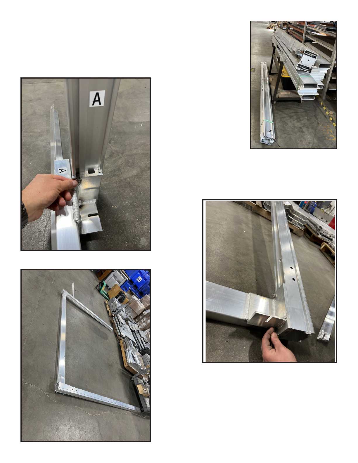
Step 1- The Uprights
Unpackage the bundles. Lay all parts out on a level surface.
Locate the (2) lower side beams. e le lower side beam ends will be labeled A
and D. e right lower side beam will be labeled B and C.
Locate the (4) upright posts. Match the labeled uprights with their
corresponding corners.
Insert upright A into the A
corner. Locate hardware bag (1).
Insert the head of (1)3/8” x 1”
carriage bolt in the nut channel
from the top of the upright. Slide
the carriage bolt all the way down
until it rests in the slot on the
bracket of the side beam. Secure
with (1) 3/8” ange nut.
Repeat for the remaining corners
and uprights.
Insert the head of (1)3/8” x 1” carriage bolt in the nut channel
from the bottom of the upright. Slide the carriage bolt up until it
rests in the slot on the bracket of the side beam. Secure with (1)
3/8” ange nut.
Repeat for the remaining corners and uprights.

Step 2- The Leveling Legs
Locate the (4) leveling leg posts and the (4) foot
pads.
Insert the legs in to the foot pads and secure with
3/8” x 3-1/2” bolt and 3/8” ange nut.
Insert legs into the upright posts on each corner.
Secure with leg pin and clip. Leave the legs in the
bottom hole for assembly purposes. Do this on all 4
corners.
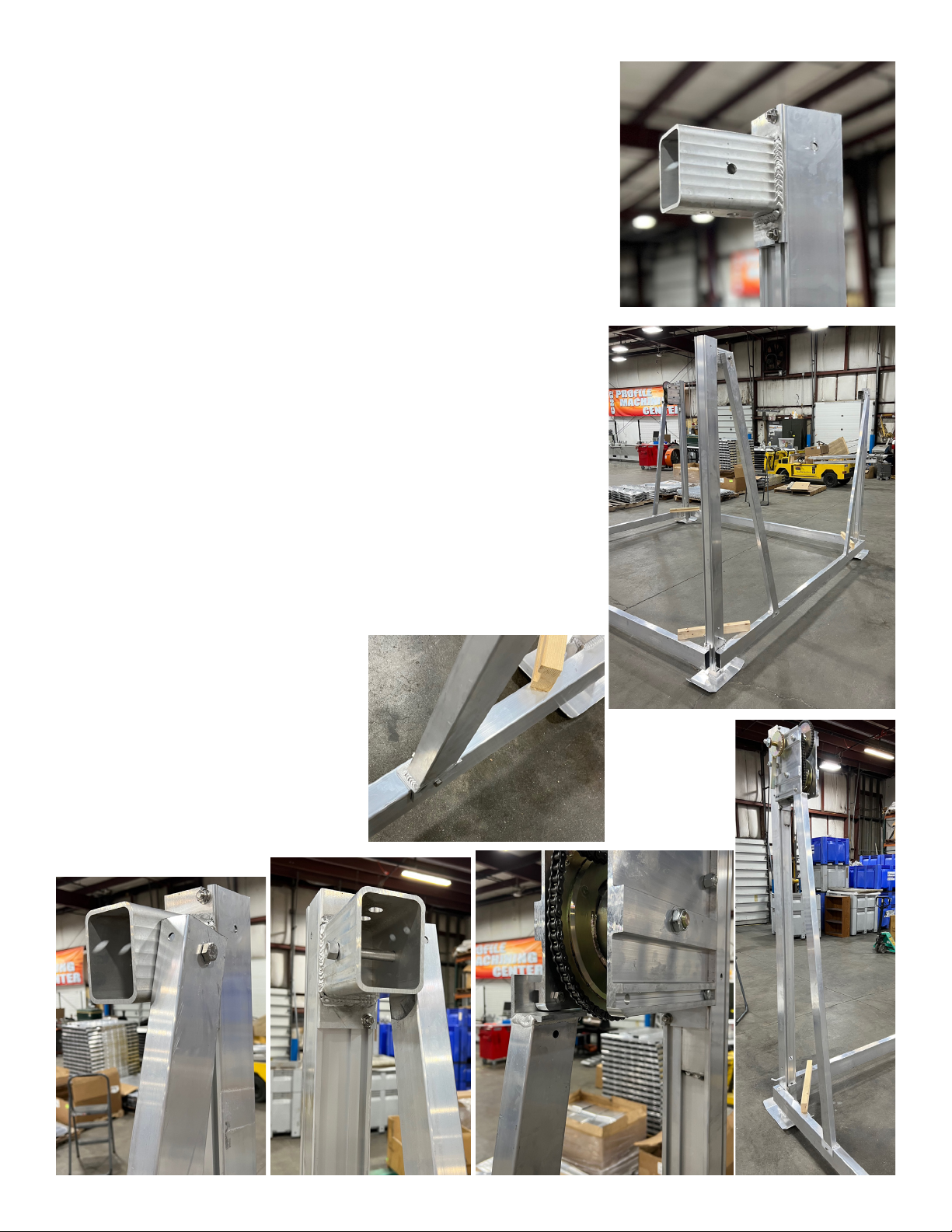
Step 3- Attaching the Winch
On upright A, slide (1) 3/8” x 1” carriage bolt
in the nut channel. Slide the winch box over
upright A. e winch will stop on a plate
welded in the slot.
HINT: WD-40 might help the winch slide on
the post easier.
Slide the carriage bolt up into the slot in the
winch mount and fasten with (1) 3/8” ange
nut.
Insert another 3/8” x 1” carriage bolt into the
slot on the top of the winch mount and fasten
with (1) 3/8” ange nut similar to the bottom
of the winch mount.
Tighten the nuts.

Go to corner C. Slide the head of (2) 3/8” x 1” carriage bolts into the
slot on the upright post and slide into the slot on the top of the angle of
the end of the base tube. e bottom of the angle should line up with
the bottom of the upright post. Attach with 3/8” ange nuts and hand
tighten. Slide (2) more 3/8” x 1” carriage bolts and 3/8” ange nuts into
the bottom slots of the angles.
Go to corner A. Repeat the process to attach the other base tube.
Step 4- The Front and Rear Base Tubes
Step 5- Connecting the frame
Li up both sides of the frame. e front and rear base tubes will act as a
kickstand to keep the frames upright. Place the frames facing each other.
ey should form a square. Ensure that the labeled ends correspond with the
correct corner.
Go to one of the corners that needs to be attached. Insert the 3/8” x 1”
carriage bolt heads into the slots of the upright posts and angles just like the
other corners. Attach with 3/8” ange nuts. Make sure the bottom of the
angles are even with the bottom of the upright posts.
Do the same with the last corner and tighten all the bolts.
Step 6- Cable mounting bracket
Locate the (3) cable mounting brackets.
Insert the head of (1) 3/8” x 1” carriage bolt into the outer nut channel on
upright B. Hand tighten (1) 3/8” ange nut on the carriage bolt.
Slide (1) cable mounting bracket down the upright. e cable mounting
bracket should run parallel with the side beam and is ush with top of the
upright post.
Insert (1) 3/8” x 1” carriage bolt into the outer nut channel and into the
slot on top of the cable mounting bracket.
Repeat for uprights C and D.
Step 7- V braces
Locate the (4) side frame braces. ere are 3 of them that are the same
and 1 that is dierent. e dierent 1 is for the winch corner.
On the (3) similar side frame braces, line up (1) brace with the hole on
the outside of the cable mounting bracket. Secure the top of the brace
by inserting (1)1/2” x 6” bolt through the tubes. Fasten with 1/2” nut.
Fasten the bottom angle to the side frame bottom tube with (1) 3/8” x 2
3/4” bolt. Attach 3/8” ange nut and tighten.
Fasten the winch V brace to the winch with (1) 3/8” x 1” bolt and 3/8”
ange nut.
Fasten the bottom angle to the bottom side frame tube with (1) 3/8” x
2-3/4” bolt and (1) 3/8” ange nut.
Popular Lifting System manuals by other brands

probst
probst SDH-H-15 operating instructions

Bruno
Bruno OUTDOOR ELITE CRE-2110E Operator's manual

matev
matev FPS Mounting Assembly Installation Guide

Vestil
Vestil CYL-HLT Series instruction manual

Butts Tools
Butts Tools BXS0002 operating instructions

Safelift
Safelift MoveAround MA60 Original instructions


R. Beck Maschinenbau
R. Beck Maschinenbau HS 600 operating manual

Nova Technology International, LLC
Nova Technology International, LLC NAS Series quick start guide

Genie
Genie Z-60/34 Operator's manual

Screen Technics
Screen Technics INTERFIT Vertical Up Lift instructions

Drive
Drive DUPONT SAMERY Hermes user manual

Custom Equipment
Custom Equipment Hy-Brid 3 Series MAINTENANCE & TROUBLESHOOTING MANUAL