Hardinge FlexC Dead-Length 65 Datasheet
1
65mm FlexC™ Collet System Style DL Instructions B-152C
Hardinge Inc. One Hardinge Drive, Elmira, New York U.S.A. 14902-1507 800.843.8801 (Canada 800.468.5946) www.shophardinge.com
Part No. BC -0009500-0152
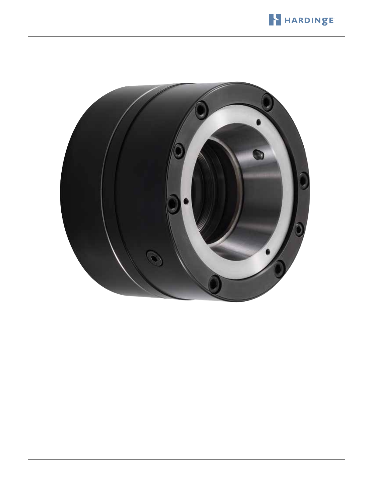
Hardinge FlexC™ Dead-Length®Collet System
Style DL — 65mm
Installation Instructions
and Parts Lists

2
65mm FlexC™ Collet System Style DL Instructions B-152C
Hardinge Inc. One Hardinge Drive, Elmira, NewYork U.S.A. 14902-1507 800.843.8801 (Canada 800.468.5946) www.shophardinge.com
Part No. BC -0009500-0152
General Safety Information
Before installing the Hardinge®FlexC™Collet System on your machine tool, thoroughly read this manual and understand
the information. If you are uncertain about any of the information, see your immediate supervisor. Also make certain that
you understand the information in your machine tool operator’s, programmer’s and maintenance manuals.
NOTICE
Damage resulting from misuse, negligence or accidents
is not covered by the Hardinge FlexC warranty.
Information in this document is subject to change without notice.
In no event will Hardinge Inc. be responsible for indirect or consequential damage
resulting from the use or application of the product, or any of the information in this document.
This product is only to be used by trained machinists skilled
in the use and operation of collet systems and collet chucks on metal cutting machines.
Safety Requirements to the Turning Machine:
Check to see that the workpiece is properly gripped and seated in the collet head before beginning the machining cycle.
Do not unclamp the workpiece until the machining cycle has come to a complete stop.
Observe all safety precautions indicated in the machine manual when operating the machine including the use of guards
and keeping the door closed during machining.
Do not exceed the maximum operating force and rpm for the Hardinge FlexC Collet Systems indicated below:
Maximum operating force: 10,100 lb (45KN)
Maximum RPM: 6,000
Product Description and Use:
The Hardinge FlexC style DL Collet System consists of a spindle mount assembly. Vulcanized collet heads and wrenches are
purchased separately. The style DL Dead-length®Collet System can be used as a thru-hole for bar work or with a work
stop for chucking. The clamping heads consist of hardened steel segments that are joined together by a vulcanization pro-
cess. Their outstanding characteristics include parallel workpiece clamping, superb accuracy with a minimum of deformation
of the work piece, and quick-change capability. If the Hardinge FlexC style DL Collet System is used as a dead-length system
the work stop is inserted into the workstop adapter with the part stop wrench included. When part length control is not
required the work stop can be removed.
The Hardinge FlexC style DL 65mm Collet Systems use a push-to-close design with an axially-xed collet head. They are
ideally suited for sub-spindles to maintain length control during secondary operations. The push-to-close design also avoids
axial stress between the spindles. The collet head is xed in the spindle mount, while the drawbar moves forward and
closes the collet head.

3
65mm FlexC™ Collet System Style DL Instructions B-152C
Hardinge Inc. One Hardinge Drive, Elmira, NewYork U.S.A. 14902-1507 800.843.8801 (Canada 800.468.5946) www.shophardinge.com
Part No. BC -0009500-0152
CAUTION: Make sure that the workpiece is adequately gripped so that the workpiece will not come loose
during the machining process. When clamping very short workpieces, the minimum clamping lengths must be observed.
They depend on the selected clamping head size and shape – call Hardinge for guidance. Do not clamp tapered work
pieces. In general the collet system should never be rotated without a clamped workpiece. Never rotate the collet
system over 2,000 RPM without a clamped workpiece. When actuating the changing wrench, never reach inside the
moving parts for risk of severely damaging your hand.
Drawbar Linkup
The Hardinge FlexC Collet System requires a drawbar linkup to mate the specic machine drawbar (varies by machine brand
and model) to the FlexC clamping sleeve. This linkup can be ordered from Hardinge or can be made by the customer.
Cleaning and Maintenance
The spindle, collet head and the spindle mount mating surfaces must be cleaned and free of chips and sludge whenever
mounting to the spindle or changing out a collet head. Visually inspect collets for tearing or separation of rubber on a
regular basis during long job runs and during setup. If you are using a high pressure coolant in your machining processes,
you need to inspect the collets more frequently. Do NOT clean an open spindle with an air hose as chips and sludge may
be forced into the spindle drawbar area. Clean and lubricate all moving parts with Chevron Ultra-Duty EP NLGI 2, Dow
Corning BR-2-Plus, or Kluber ALTEMP Q NB 50 grease. Store all unused products properly to prevent corrosion and
keep free of dust and environmental particles.
Check to see that all mounting screws are in good condition and replace when worn. All components must be replaced
with original Hardinge replacement parts.

4
65mm FlexC™ Collet System Style DL Instructions B-152C
Hardinge Inc. One Hardinge Drive, Elmira, NewYork U.S.A. 14902-1507 800.843.8801 (Canada 800.468.5946) www.shophardinge.com
Part No. BC -0009500-0152
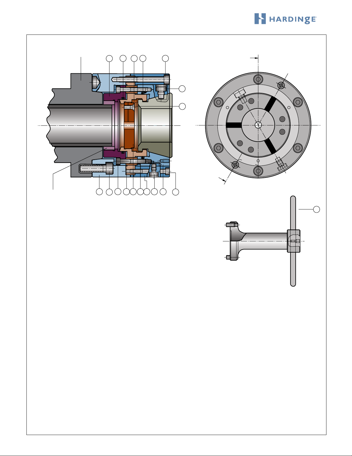
Spindle
B
A
SECTION A-B
15 16
17 18
9
19
21
120
4
56728322
PART STOP WRENCH
Drawbar Linkup
may be required
10
Drawbar
A2-5 Assembly #V65-5DL05700 Parts List:
ITEM PART NUMBER QTY DESCRIPTION
1 V65-5DL05701 1 Chuck Flange
2 V65-6DL05802 1 Chuck Body
3 V65-6DL05803 1 Collet Seat
4 V65-6DL05904 1 Drawbar Adapter (separate item)*
5 V65-6DL05805 1 Coupling Stop
6 V65-6DL05806 1 Part Stop
7 V65-6DL05807 6 Spacer
8 V65-0200 1 Key for Collet Seat
9 V65-01207 1 Key for Collet Head
10 V65-6DL05810 1 Part Stop Wrench
15 CE 00094318288 1 O-Ring
16 CE 000943197104 1 O-Ring
17 V65-6DL11601 1 Seal
18 MS-0103828 6 M8x70 SHCS (26ft-lb/36Nm)
19 MS-0313617 1 M6x16 Flathead Screw
20 MS-0104019 4 M10x25 SHCS (40ft-lb/54Nm)
21 MS-0103622 6 M6x40 SHCS
22 MS-0103625 2 M6x55 SHCS
* No additional charge unless a drawbar linkup is required.

5
65mm FlexC™ Collet System Style DL Instructions B-152C
Hardinge Inc. One Hardinge Drive, Elmira, NewYork U.S.A. 14902-1507 800.843.8801 (Canada 800.468.5946) www.shophardinge.com
Part No. BC -0009500-0152
Spindle
B
A
SECTION A-B
15 16
17 18
9
19
21
120
4
56728322
PART STOP WRENCH
Drawbar Linkup
may be required
10
Drawbar
A2-6 Assembly #V65-6DL05900 Parts List:
ITEM PART NUMBER QTY DESCRIPTION
1 V65-6DL05901 1 Chuck Flange
2 V65-6DL05802 1 Chuck Body
3 V65-6DL05803 1 Collet Seat
4 V65-6DL05904 1 Drawbar Adapter (separate item)*
5 V65-6DL05805 1 Coupling Stop
6 V65-6DL05806 1 Part Stop
7 V65-6DL05807 6 Spacer
8 V65-0200 1 Key for Collet Seat
9 V65-01207 1 Key for Collet Head
10 V65-6DL05810 1 Part Stop Wrench
15 CE 00094318288 1 O-Ring
16 CE 000943197104 1 O-Ring
17 V65-6DL11601 1 Seal
18 MS-0103828 6 M8x70 SHCS (26ft-lb/36Nm)
19 MS-0313617 1 M6x16 Flathead Screw
20 MS-0104222 4 M12x40 SHCS (60ft-lb/81Nm)
21 MS-0103622 6 M6x40 SHCS
22 MS-0103625 2 M6x55 SHCS
* No additional charge unless a drawbar linkup is required.
6
65mm FlexC™ Collet System Style DL Instructions B-152C
Hardinge Inc. One Hardinge Drive, Elmira, NewYork U.S.A. 14902-1507 800.843.8801 (Canada 800.468.5946) www.shophardinge.com
Part No. BC -0009500-0152
Spindle
B
A
SECTION A-B
15 16
17 18
9
19
21
120
4
56728322
PART STOP WRENCH
Drawbar Linkup
may be required
10
Drawbar
A2-8 Assembly #V65-8DL06000 Parts List:
ITEM PART NUMBER QTY DESCRIPTION
1 V65-8DL06001 1 Chuck Flange
2 V65-6DL05802 1 Chuck Body
3 V65-6DL05803 1 Collet Seat
4 V65-6DL05904 1 Drawbar Adapter (separate item)*
5 V65-6DL05805 1 Coupling Stop
6 V65-6DL05806 1 Part Stop
7 V65-6DL05807 6 Spacer
8 V65-0200 1 Key for Collet Seat
9 V65-01207 1 Key for Collet Head
10 V65-6DL05810 1 Part Stop Wrench
15 CE 00094318288 1 O-Ring
16 CE 000943197104 1 O-Ring
17 V65-6DL11601 1 Seal
18 MS-0103828 6 M8x70 SHCS (26ft-lb/36Nm)
19 MS-0313617 1 M6x16 Flathead Screw
20 MS-0104622 4 M16x40 SHCS (90ft-lb/122Nm)
21 MS-0103622 6 M6x40 SHCS
22 MS-0103625 2 M6x55 SHCS
* No additional charge unless a drawbar linkup is required.

7
65mm FlexC™ Collet System Style DL Instructions B-152C
Hardinge Inc. One Hardinge Drive, Elmira, NewYork U.S.A. 14902-1507 800.843.8801 (Canada 800.468.5946) www.shophardinge.com
Part No. BC -0009500-0152
Spindle
B
A
SECTION A-B
15 16
17 18
9
19
21
120
4
56728322
PART STOP WRENCH
Drawbar Linkup
may be required
10
Drawbar
140mm Assembly #V65-140DL02400 Parts List:
ITEM PART NUMBER QTY DESCRIPTION
1 V65-140DL02401 1 Chuck Flange
2 V65-6DL05802 1 Chuck Body
3 V65-6DL05803 1 Collet Seat
4 V65-6DL05904 1 Drawbar Adapter (separate item)*
5 V65-6DL05805 1 Coupling Stop
6 V65-6DL05806 1 Part Stop
7 V65-6DL05807 6 Spacer
8 V65-0200 1 Key for Collet Seat
9 V65-01207 1 Key for Collet Head
10 V65-6DL05810 1 Part Stop Wrench
15 CE 00094318288 1 O-Ring
16 CE 000943197104 1 O-Ring
17 V65-6DL11601 1 Seal
18 MS-0103828 6 M8x70 SHCS (26ft-lb/36Nm)
19 MS-0313617 1 M6x16 Flathead Screw
20 MS-0104020 6 M10x30 SHCS (40ft-lb/54Nm)
21 MS-0103622 6 M6x40 SHCS
22 MS-0103625 2 M6x55 SHCS
* No additional charge unless a drawbar linkup is required.

8
65mm FlexC™ Collet System Style DL Instructions B-152C
Hardinge Inc. One Hardinge Drive, Elmira, NewYork U.S.A. 14902-1507 800.843.8801 (Canada 800.468.5946) www.shophardinge.com
Part No. BC -0009500-0152
Installation
The spindle adapter and collet seat assembly are shipped assembled. The spindle
adapter must be separated from the body by removing the six mounting screws
#18. Inspect the six fastening screws #21 to ensure a torque of 7.375 ft-lb
(10Nm). Tighten if necessary.
Clean, inspect and grease the machine spindle and the spindle adapter. Mount the
spindle adapter to the machine spindle using the four fastening screws #20. For A2
style spindles, orient the spindle adapter with the drive button. Tighten the fasten-
ing screws to the appropriate torque shown in the parts list. Flat back spindles
must be indicated before you torque the bolts to specication.
Check the concentricity and face runout of the spindle adapter before mounting the
collet seat assembly. Neither should exceed .0002" (5µm). If the indicator reading is more than
.0002" (5µm), remove the spindle adapter and clean the surfaces again before remounting.
Reduce the clamping pressure of the machine to a minimum and extend the drawbar to the forward position. Carefully
screw the collet seat assembly onto the drawbar clockwise until it bottoms out. DO NOT TIGHTEN. Rotate the body
counterclockwise until the clearance holes in the body line up with the threaded holes on the spindle adapter. Carefully
move the drawbar backwards and seat the collet seat assembly into the spindle adapter. Insert and tighten the six mount-
ing screws #18 equally to 26 ft-lb (36Nm) torque.
Increase the clamping pressure to sufcient force for the job.
Checking the Final Concentricity of the Collet Closing Taper
Locate the probe to touch the inside closing taper of the body to verify concentricity. This should not exceed .0006"
(15µm). If the indicator reading is more than .0006" (15µm), remove the body and clean the surfaces of the spindle adapter
and the body again before remounting. Check the concentricity again and repeat this step until the desired reading is met.
Concentricity may be affected if using stock beyond the nominal gripping range.
Installing a Collet Head
Installing or changing of the collet head is possible only
when the chuck is in the unclamped position. Prior to
inserting the collet head you must clean the taper of the
collet seat and the mating taper of the collet head.
Fully insert the pins of the manual wrench into the holes
in the face of the collet head. Actuate or pull the lever
to collapse the segments before inserting it into the col-
let seat. Insert applying light pressure. Orient the keyway
in the collet head with the key #9 in the collet seat. To
release the collet head from the manual wrench you
must press on the release button.
CAUTION: When actuating the manual wrench never
reach inside the moving parts where there is risk of
injury to your hand. Clean and lightly oil the collet head
and the body before installing.
release
button
keyway
spindle
adapter collet seat
assembly

9
65mm FlexC™ Collet System Style DL Instructions B-152C
Hardinge Inc. One Hardinge Drive, Elmira, NewYork U.S.A. 14902-1507 800.843.8801 (Canada 800.468.5946) www.shophardinge.com
Part No. BC -0009500-0152
Spindle
B
A
SECTION A-B
17
19
6
10 PART STOP WRENCH
Removing or Changing the Work Stop
Follow the previous instructions to remove the collet head
before changing the work stop. The collet head must be in
the unclamp position. Reach in and remove the seal #17
and set it aside.
Turn the locking screw #19 counterclockwise to loosen the
threads to allow the removal of the work stop #6. It is not
necessary to remove the locking screw.
A work stop wrench #10 is supplied with the spindle
mount assembly to remove the work stop. Align and insert
the pins of the wrench into the holes in the face of the
work stop. Turn the wrench counterclockwise to unscrew
the work stop. If you feel resistance you must go back and
loosen the locking screw #19.
The work stop has an M12 thread in the center to secure a custom work stop for required workpiece applications.
To reassemble, simply follow the same instructions in reverse order. Insert the work stop with the two pin holes facing out.
Tighten the locking screw by hand to ensure that there will be no movement in the dead-length®work stop. Remember to
replace the seal #17 before inserting your collet head. Failure to use the seal may cause malfunction of the collet system.
This manual suits for next models
4
Table of contents
Other Hardinge Lathe manuals


