Jet JWL-2020-M User manual

JWL-2035-M
JWL-2020-M
WOOD LATHE
Original:
GB
Operating Instructions
Translations:
D
Gebrauchsanleitung
F
Mode d´emploi
JPW (Tool) AG
Tämplerlistrasse 5
CH-8117 Fällanden
Switzerland
Phone +41 44 806 47 48
Fax +41 44 806 47 58
www.jettools.com
M-JWL-2035-M 2016 -12

CE-Conformity Declaration
CE-Konformitätserklärung
Déclaration de Conformité CE
Product / Produkt / Produit:
Wood Lathe / Drechselbank / Tour a bois
JWL-2035-M
JWL-2020-M
Brand / Marke / Marque:
JET
Manufacturer / Hersteller / Fabricant:
JPW (Tool) AG, Tämperlistrasse 5, CH-8117 Fällanden
Switzerland / Schweiz / Suisse
We hereby declare that this product complies with the regulations
Wir erklären hiermit, dass dieses Produkt der folgenden Richtlinie entspricht
Par la présente, nous déclarons que ce produit correspond aux directives suivantes
2006/42/EC
Machinery Directive / Maschinenrichtlinie / Directive Machines
2014/30/EU
electromagnetic compatibility / elektromagnetische Verträglichkeit / compatibilité électromagnétique
designed in consideration of the standards
und entspechend folgender zusätzlicher Normen entwickelt wurde
et été développé dans le respect des normes complémentaires suivantes
EN ISO 12100:2010
EN 60204-1:2006+A1:2009
EN 61000-6-4:2007+A1:2011
EN 61800-3:2004+A1:2012
EN 55011:2009+A1:2010
Responsible for the Documentation / Dokumentations-Verantwortung / Résponsabilité de Documentation:
Hansjörg Meier
Head Product-Mgmt. / Leiter Produkt-Mgmt. / Resp. Gestion des Produits
JPW (Tool) AG
2016-12-01 Alain Schmid, General Manager
JPW (Tool) AG, Tämperlistrasse 5, CH-8117 Fällanden
Switzerland / Schweiz / Suisse
2

GB - ENGLISH
Operating Instructions
Dear Customer,
Many thanks for the confidence you have shown in us with the purchase of your new JET-machine. This manual has been
prepared for the owner and operators of a JET JWL-2035-M and JWL-2020-M wood lathe to promote safety during installation,
operation and maintenance procedures. Please read and understand the information contained in these operating instructions and
the accompanying documents. To obtain maximum life and efficiency from your machine, and to use the machine safely, read this
manual thoroughly and follow instructions carefully.
…Table of Contents
1. Declaration of conformity
2. JET Warranty
3. Safety
Authorized use
General safety notes
Remaining hazards
4. Machine specifications
Machine description
Technical data
Noise emission
Contents of delivery
5. Transport and start up
Transport and installation
Assembly
Mains connection
Dust collection
Starting operation
6. Machine operation
Correct operating position
Tool selection
Speed selection
Turning between centres
Bowl turning
Sanding and Finishing
7. Setup and adjustments
Changing spindle speeds
Headstock spindle lock
Headstock rotation
Headstock spindle index
Installing work holding
Adjusting tool rest
Adjusting tailstock
8. Maintenance and inspection
Adjusting bed clamping
Pulley drive lubrication
Changing belt and bearings
9. Trouble shooting
10. Environmental protection
11. Available accessories
1. Declaration of conformity
On our own responsibility we hereby declare that this product
complies with the regulations* listed on page 2. Designed in
consideration with the standards**.
2. JET Group Warranty
The JET Group makes every effort to assure that its products
meet high quality and durability standards and warrants to the
original retail consumer/purchaser of our products that each
product be free from defects in materials and workmanship as
follows:
2 YEAR LIMITED WARRANTY ON ALL PRODUCTS
UNLESS SPECIFIED OTHERWISE.
This Warranty does not apply to defects due to directly or
indirectly misuse, abuse, negligence or accidents, normal
wear-and-tear, repair or alterations outside our facilities, or to
a lack of maintenance.
The JET group limits all implied warranties to the period
specified above, from the date the product was purchased at
retail.
To take advantage of this warranty, the product or part must
be returned for examination, postage prepaid, to an
authorized repair station designated by our office.
Proof of purchase date and an explanation of the complaint
must accompany the merchandise.
If our inspection discloses a defect, we will either repair or
replace the product, or refund the purchase price if we cannot
readily and quickly provide a repair or replacement, if you are
willing to accept a refund.
We will return repaired product or replacement at JET’S
expense, but if it is determined there is no defect, or that the
defect resulted from causes not within the scope of JET’S
warranty, then the user must bear the cost of storing and
returning the product.
The JET Group reserves the right to make alterations to
parts, fittings, and accessory equipment which they may
deem necessary for any reason whatsoever.
3. Safety
3.1 Authorized use
This wood lathe is designed for turning wood only. Machining
of other materials is not permitted and may be carried out in
specific cases only after consulting with the manufacturer.
The workpiece must allow to safely be loaded and supported.
The proper use also includes compliance with the operating
and maintenance instructions given in this manual.

The machine must be operated only by persons familiar with
its operation and maintenance and who are familiar with its
hazards.
The required minimum age must be observed.
The machine must only be used in a technically perfect
condition.
When working on the machine, all safety mechanisms and
covers must be mounted.
In addition to the safety requirements contained in these
operating instructions and your country’s applicable
regulations, you should observe the generally recognized
technical rules concerning the operation of woodworking
machines.
Any other use exceeds authorization.
In the event of unauthorized use of the machine, the
manufacturer renounces all liability and the responsibility is
transferred exclusively to the operator
3.2 General safety notes
Woodworking machines can be dangerous if not used
properly. Therefore the appropriate general technical rules as
well as the following notes must be observed.
Read and understand the entire instruction manual before
attempting assembly or operation.
Keep this operating instruction close by the machine,
protected from dirt and humidity, and pass it over to the new
owner if you part with the tool.
No changes to the machine may be made.
Daily inspect the function and existence of the safety
appliances before you start the machine.
Do not attempt operation in this case, protect the machine by
unplugging the mains cable.
Before operating the machine, remove tie, rings, watches,
other jewellery, and roll up sleeves above the elbows.
Remove all loose clothing and confine long hair.
Wear safety shoes; never wear leisure shoes or sandals.
Always wear the approved working outfit:
- safety goggles
- ear protection
- dust protection
Do not wear gloves while operating this machine.
Install the machine so that there is sufficient space for safe
operation and workpiece handling.
Keep work area well lighted.
The machine is designed to operate in closed rooms and
must be placed stable on firm and levelled table surface.
Make sure that the power cord does not impede work and
cause people to trip.
Keep the floor around the machine clean and free of scrap
material, oil and grease.
Stay alert, give your work undivided attention.
Use common sense. Do not operate the machine when you
are tired.
Do not operate the machine under the influence of drugs,
alcohol or any medication. Be aware that medication can
change your behaviour.
Keep an ergonomic body position.
Maintain a balanced stance at all times.
Never reach into the machine while it is operating or running
down.
Keep children and visitors a safe distance from the work area.
Never leave a running machine unattended. Before you leave
the workplace switch off the machine.
Do not operate the electric tool near inflammable liquids or
gases.
Observe the fire fighting and fire alert options, for example
the fire extinguisher operation and place.
Do not use the machine in a dump environment and do not
expose it to rain.
Wood dust is explosive and can also represent a risk to
health.
Dust form some tropical woods in particular, and from
hardwoods like beach and oak, is classified as a carcinogenic
substance.
Always use a suitable dust collection device
Before machining, remove any nails and other foreign bodies
from the workpiece.
Make sure to guide and hold the chisel with both hands safe
and tight during machining.

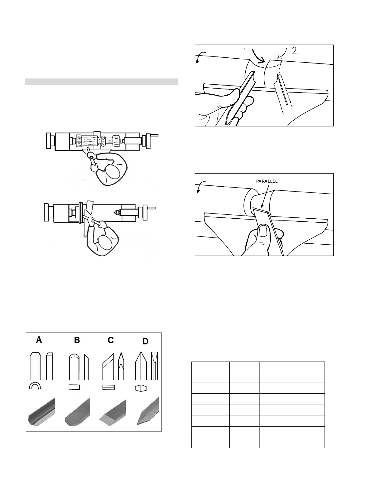
Work only with well sharpened tools.
Machine only stock which is chucked securely on the
machine, always check before switching the machine on.
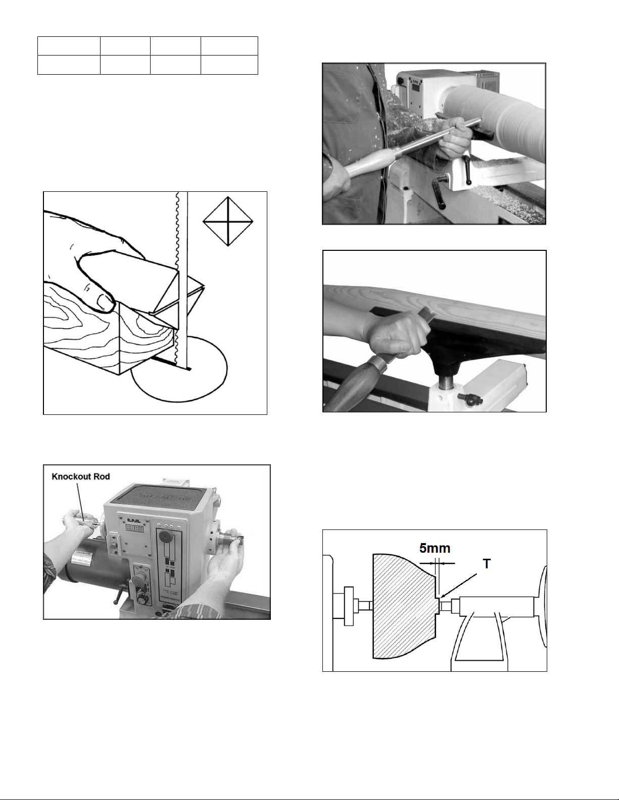
Provide workpieces with centre holes before clamping
between centres.
Work large and unbalanced workpieces at low spindle speed
only.
When sanding, remove the tool rest from the machine.
Workpieces with cracks may not be used.
Remove the chuck key or dowel pins before turning the
machine on.
Always close the belt cover.
Specifications regarding the maximum or minimum size of the
workpiece must be observed.
Test each set-up by revolving the work by hand to insure it
clears the tool rest and bed. Check setup at the lowest speed
before you increase to the operating speed.
Do not remove chips and workpiece parts until the machine is
at a standstill.
Never stop work pieces with the hand during run out.
Do not attempt to engage the spindle lock pin until the spindle
has stopped.
Never take measurements on a rotating workpiece.
Do not stand on the machine.
Do not obstruct the air flow on heat sinks of AC-drive (allow
natural cooling).
Connection and repair work on the electrical installation may
be carried out by a qualified electrician only.
(Warning: Wait five minutes for DC-bus capacitors discharge
before accessing the AC drive unit.)
Have a damaged or worn power cord replaced immediately.
Make all machine adjustments or maintenance with the
machine unplugged from the power source.
3.3 Remaining hazards
When using the machine according to regulations some
remaining hazards may still exist.
The rotating workpiece can cause injury.
Workpieces that are inhomogeneous or weak can explode
when being processed due to centrifugal force.
Only process selected woods without defects.
Unbalanced workpieces can be hazardous.
Injuries can occur when feeding tooling, if tool supports are
not correctly adjusted or if turning tools are blunt.
Risk of kickback. The tooling is caught by the rotating
workpiece and thrown back to the operator.
Thrown workpieces and workpiece parts can lead to injury.
Dust and noise can be health hazards. Be sure to wear
personal protection gear such as safety goggles and dust
mask. Use a suitable dust collection system.
The use of incorrect mains supply or a damaged power cord
can lead to injuries caused by electricity.
4. Machine specifications
4.1 Technical data
Swing over bed 508mm
Swing over tool rest base 406mm
Centre distance (JWL-2035-M) 800mm
Centre distance (JWL-2020-M) 508mm
Number of mechanical speeds 2
Spindle speed range 1 0-1200 rpm
Spindle speed range 2 0-3200 rpm
Spindle nose M33x3.5 DIN 800
Headstock spindle taper MT 2
Spindle index lock 24x15°, 36x10°
Spindle hole diameter 15.8mm
Tailstock spindle taper MT 2
Tailstock hole diameter 9,5mm
Tailstock ram travel 115mm
Centre above floor 1120mm
Overall for JWL-2035-M (LxWxH) 1974x690x1470mm
Overall for JWL-2020-M (LxWxH) 1581x690x1470mm
Footprint for JWL-2035-M (LxW) 1270x610mm
Footprint for JWL-2020-M (LxW) 890x610mm
Net weight for JWL-2035-M 290 kg
Net weight for JWL-2020-M 254 kg
Mains 1~230V, PE, 50Hz
Output power 1.5 kW (2 HP) S1
Reference current 10 A
Extension cord (H07RN-F): 3x1.5mm²
Installation fuse protection 16A
Protection class I
4.2 Noise emission
Acoustic pressure level (according to EN ISO 11202):
Idling LpA 72.5 dB(A)
In operation LpA 78.4 dB(A)
The specified values are emission levels and are not
necessarily to be seen as safe operating levels.
As workplace conditions vary, this information is intended to
allow the user to make a better estimation of the hazards and
risks involved only.

4.3 Content of delivery
Casting legs with levelling pads
350 mm tool rest
75 mm face plate
Spur centre and tooling knockout bar
Live centre
Guard
Tool caddy
Comparator centres,Has not included in JWL-2020-M lathe,
(S & T, Fig 1)
Remote ON/OFF switch
Operating tools
Assembly kit
Operating manual
Spare parts list.
Fig 1
5. Transport and start up
5.1 Transport and installation
The machine is designed to operate in closed rooms and
must be placed stable on firm and levelled ground.
The machine can be bolted down if required.
For packing reasons the machine is not completely
assembled
5.2 Assembly
If you notice transport damage while unpacking, notify your
supplier immediately. Do not operate the machine!
Dispose of the packing in an environmentally friendly manner.
Clean all rust protected surfaces with a mild solvent.
Attach the leg stand:
At this point the headstock, tailstock and tool rest should be
removed.
The machine bed is heavy! With the help of a second person,
carefully lift bed up onto a workbench.
Attach the leg stand with 8 hex socket cap screws and 8 flat
washers (A, Fig 2).
Fig 2
Thread adjustable feet (D) into stand leg (B).
Adjust the feet so that the lathe rests evenly on the floor, and
tighten the nuts (C).
Reinstall headstock, tailstock and tool rest.
Tool caddy assembly:
Mount the tool caddy with two screws and lock washers to the
left leg (Fig 3)
Fig 3

The tailstock body can also be used to store tools (Fig 4).
Fig 4
Stand shelf:
You can make an extra shelf that rests between the legs if
you wish (Fig 5-7).
Fig 5
Fig 6
Fig 7
Guard assembly:
Attach guard to the bracket by inserting the rod and lifting up
on the plunger (A, Fig 8).
Fig 8
There are two detents that will hold the guard in place.
One is for turning and the other is for when you need the
guard up and out of the way.
Tighten the bushings (B) against the bracket with two set
screws (C).
Fig 9

Comparator assembly:
Has not included in JWL-2020-M lathe.
Mount the comparator rear bracket (A, Fig 10) to the back of
the tailstock with two socket head cap screws, lock washers
and washers (B).
The bracket has a slot so it can be aligned with the bracket
on the headstock.
The comparator allows to hold a sample workpiece for optical
reference and comparative measurement taking.
( see Fig 11-12).
Fig 10
Fig 11
Fig 12
5.3 Mains connection
Mains connection and any extension cords used must comply
with applicable regulations.
The mains voltage must comply with the information on the
machine licence plate.
The mains connection must have a
16 A surge-proof fuse.
Only use power cords marked H07RN-F
Connections and repairs to the electrical equipment may only
be carried out by qualified electricians.
5.4 Dust collection
Use a suitable dust collection and filtration system to avoid a
high dust concentration in the air.
5.5 Starting operation
You can start the machine with the green ON-button. The red
Off-button stops the machine. (A, Fig 13).
Fig 13
The machine will stop when you push the red OFF-button (A,
Fig 13) or the remote control ON/OFF button (Fig 14).
When remote switch is pushed, cycle the green ON-
button (A, Fig 13) on headstock to restart lathe.
Fig 14
Turn the knob (C) to the desired RPM. There are 2 speed
ranges offering “speed” (0-3200 rpm) and
“torque” (0-1200 rpm).

The RPM readout shows the spindle speed
Use the toggle switch (B) to reverse the spindle direction.
The headstock lock handle locks the headstock in position.
Unlock handle to position the head along the lathe bed.
6. Machine operation
6.1 Correct operating position
Always support the tool on the tool rest and guide with the
palm of your hand keeping your fingers closed.
(see Fig. 15 )
Fig 15
6.2 Tool selection
Successful wood turning does not result from high speeds,
but rather, from the correct use of turning tools.
A perfect and sharp wood turner tool is a precondition for
professional wood-turning.
Major tools:
Fig 16
Gouge (A, Fig 16), used for rapidly cut raw wood into round
stock, for turning bowls and plates, for turning beds, coves
and other detail (Fig 17).
Fig 17
Scraper (B, Fig 16), used for diameter scraping and to
reduce ridges.
Skew Chisel (C, Fig 16), used to make vees, beads, etc. (Fig
18). The bevel of scew is parallel to the cut.
Fig 18
Parting tool (D, Fig 16), used to cut directly into the material,
or to make a cut off. Also used for scraping and to set
diameters.
6.3 Speed selection:
Use low speeds for roughing and for large diameter work. If
vibrations occur, stop the machine and correct the cause.
See speed recommendations.
Speed recommendations
Workpiece
Diameter
mm
Roughing
RPM
General
Cutting
RPM
Finishing
RPM
< 50
1500
3200
3200
50-100
700
1600
2500
100-150
500
1100
1600
150-200
370
800
1200
200-250
300
650
1000
250-300
250
500
800

300-350
220
450
700
350-400
180
400
600
6.4 Turning between centres
With a ruler locate and mark the centre on each end.
Put a dimple in each end of the shock. Extremely hard woods
may require kerfs cut into the spur drive end of stock (see Fig
19).
Fig 19
The spur drive centre locks into the cleaned spindle taper and
can be removed with the knockout rod (Fig 20)
Fig 20
Mount the centred workpiece between the spur drive centre
and the tailstock mounted live centre
Turn the tailstock hand wheel until the live centre well
penetrates the workpiece. Reverse the hand wheel by one
quarter turn and lock the tailstock spindle.
Turn the workpiece by hand to see if it rests securely between
centres and can be rotated freely.
For turning between centres the tool rest is set appr. 3mm
higher than centre line (Fig 21 and 22).
Fig 21
Fig 22
6.5 Bowl turning
Turn outside of bowl between centres.
Turn a short tenon the size of the hole in the faceplate (T, Fig
23). This will allow centring the workpiece.
Fig 23
Mount the workpiece (A, Fig 24) directly to the face plate
using 4 wood screws (C) from the back. Be careful to use
screws short enough not to interfere with the cutting process
but long enough to hold the workpiece securely to the face
plate.

If screw mounting is not allowed at all, the work may be glued
to a backing block (D) and the backing block screwed to the
face plate. A piece of paper in the glue joint will prevent
damaging the wood when separated later.
Mount the face plate with the workpiece already attached
onto the spindle nose thread and hand tighten.
Move tailstock away, remove centre from tailstock to prevent
injury.
Turn the workpiece by hand to see if it rests securely and can
be rotated freely.
Fig 24
For face plate turning the tool rest is set slightly lower than
centreline.
Caution:
Cut with your chisel on the left side of the turning centre only.
Use left hand to control cutting edge of gouge, while right
hand swings tool handle around toward your body (Fig 25).
Fig 25
Try to make one, very light continuous movement from the
rim to the bottom of the bowl to ensure a clean, sweeping
curve through the workpiece.
Move tool support to the exterior to re-define bottom of bowl.
6.6 Sanding and Finishing
Remove the tool rest and begin with a fine grit sandpaper
(120 grit) and progress through each grit, using only light
pressure.
Use power sanding techniques to avoid concentric sanding
marks.
Finish sanding with 220 grit.
Apply first coat of finish. Allow to dry before sanding again
with 320 or 400 grit sandpaper.
Turn lathe back on and make a separation cut through the
base. Stop at about dia. 80mm and use a fine tooth saw to
separate the bowl from the waste.
Apply additional finish coats and allow to dry before buffing.
7. Setup and adjustments
General note:
Setup and adjustment work may only be carried out after
the machine is protected against accidental starting by
pulling the mains plug.
7.1 Changing speed range
Disconnect the machine from the power source!
Loosen the locking screw and open the belt cover.
Loosen the locking handle (A, Fig 26).
Fig 26
Lift up on the tensioning handle (B) to remove tension from
the poly v-belt.
You can now position the belt in the desired speed range.
Note:
The “High” speed range (0-3200) provides maximum speed,
where as the “Low” speed range (0-1200) will provide
maximum torque.
Lower the tensioning handle so that the weight of the motor
provides the needed tension and tighten the locking handle.
Close and lock the belt cover.

Warning:
The AC Inverter does not require any programming. It is pre-
programmed from the factory. The buttons and knob on the
face of inverter should not be changed.
7.2 Headstock spindle lock
Push in pin (E, Fig 27) to keep the spindle from turning.
Fig 27
Caution:
Never press the spindle lock while the spindle is turning!
7.3 Headstock spindle index
Thread indexing pin (Fig 28) into one of the headstock thread
holes (A;B;C;D, Fig 29).
Make sure that it locates in the spindle hole.
Fig 28
There are 12 holes in the spindle 30°apart.
Fig 29
The combination of these holes will allow you to locate your
workpiece in 10° or 15°increments (for different hole patterns
see appendix A at the end of this manual).
7.4 Installing work holding
The faceplate is used for tuning bowls. There are a number
of holes for mounting the workpiece.
Thread the faceplate onto the spindle in a clockwise direction,
and tighten two set screws (E, Fig 30).
Fig 30
Remove the faceplate by loosening two setscrews. Push in
the spindle lock and use the provided wrench (F, Fig 27).
7.5 Adjusting tool rest
Position the tool rest as close to the workpiece as possible.
Tighten handle (C, Fig 31) to lock.
Set the height to appr. 3mm above centreline. Tighten
indexable knob (D).

Fig 31
7.6 Adjusting tailstock
Turn the hand wheel (P, Fig 32) clockwise to move tailstock
spindle forward. Lock tailstock spindle with the indexable
knob (O).
Fig 32
The handle (Q) locks the tailstock in position on the bed.
The live centre can be ejected by turning the hand wheel
counter-clockwise.
To screw off the cone (R, Fig 33) the life centre must be
locked against rotation with the supplied pin (S).
Fig 33
The centring pin can be knocked out to allow deep hole
drilling operations.
8. Maintenance and inspection
General notes:
Maintenance, cleaning and repair work may only be
carried out after the machine is protected against
accidental starting by pulling the mains plug.
Clean the machine regularly.
Remove any foreign objects from the heat sinks of AC-drive
(Do not obstruct the air flow).
Inspect the proper function of the dust collection daily.
Defective safety devices must be replaces immediately.
Repair and maintenance work on the electrical system may
only be carried out by a qualified electrician.
(Warning: Wait five minutes for DC-bus capacitors
discharge before accessing the AC drive unit!)
8.1 Adjusting bed clamping
If adjustment is needed, remove the stud (A, Fig 34).
Slide the headstock, tailstock or tool rest to the edge of the
bed and slightly turn the hex nut (B).
Test the handle to make sure it securely locks.
Fig 34
8.2 Changing belt and bearings
Changing belt and bearings can be a difficult task. By
chance remove headstock and take into a repair station
for servicing.
Disconnect the machine from the power source.
Open the door and remove the belt from the lower pulley.
Loosen two set screws (A, Fig 35) and unscrew the hand
wheel.

Fig 35
Loosen and remove the clamping nut (B) and lock washer
(C).
Use a wood dowel, or aluminium stock to knock spindle
towards the tailstock. (Use a material that is softer than the
spindle so you do not mushroom end of spindle).
Go only far enough to remove the belt from spindle.
To reassemble reverse the procedure.
When reinstalling clamping nut, thread it on to the spindle
until its snug. Then back off slightly and tighten the lock
washer.
Note:
To remove the pulley for bearing replacement it is needed to
loosen the 2 set screws (C, Fig 36).
Fig 36
Make sure the pulleys are oriented properly after reassembly
for straight belt running.
9. Trouble shooting
Motor doesn’t start
*No electricity-
check mains and fuse.
*Defective switch, motor or cord-
consult an electrician.
*Overload detected on AC-drive unit-
wait and restart machine; chose low speed range belt setting
(0-1200 rpm) for better torque.
Machine vibrates excessively
*Stand on uneven floor-
adjust stand for even support.
*Workpiece is not properly centred
*The speed is too high
10. Environmental protection
Protect the environment.
Your appliance contains valuable materials which can be
recovered or recycled. Please leave it at a specialized
institution.
11. Available accessories
Stock number 6294727BE
Bed extension 460mm with tool rest shaft extension
(Fig 37-38)
Fig 37

Fig 38
Stock number 6294721E
Tailstock swing away (Fig 39)
Fig 39
Stock number 708349
Heavy outboard turning stand (Fig 40)
Fig 40
Stock number 709911
Face plate 75mm M33x3.5mm
Stock number 709921
Face plate 150mm M33x3.5mm
Stock number 709942
Four toothed spur drive centre MT2
Stock number 709960
Spindle adapter for 1”x 8TPI
Stock number 708343K
Drill chuck 13 mm, with tapered mandrel MT2
Stock number 708337
Dead cup centre MT2
Refer to the JET-Pricelist
for various tools and work holding.

DE - DEUTSCH
Gebrauchsanleitung
Sehr geehrter Kunde,
vielen Dank für das Vertrauen, welches Sie uns beim Kauf Ihrer neuen JET-Maschine entgegengebracht haben. Diese Anleitung
ist für den Inhaber und die Bediener zum Zweck einer sicheren Inbetriebnahme, Bedienung und Wartung der Drechselbank JET
JWL-2035-M & JWL-2020-M erstellt worden. Beachten Sie bitte die Informationen dieser Gebrauchsanleitung und der
beiliegenden Dokumente. Lesen Sie diese Anleitung vollständig, insbesondere die Sicherheitshinweise, bevor Sie die Maschine
zusammenbauen, in Betrieb nehmen oder warten. Um eine maximale Lebensdauer und Leistungsfähigkeit Ihrer Maschine zu
erreichen befolgen Sie bitte sorgfältig die Anweisungen.
Inhaltsverzeichnis
1. Konformitätserklärung
2. JET Garantieleistungen
3. Sicherheit
Bestimmungsgemäße Verwendung
Allgemeine Sicherheitshinweise
Restrisiken
4. Maschinenspezifikation
Technische Daten
Schallemission
Lieferumfang
5. Transport und Inbetriebnahme
Transport und Aufstellung
Montage
Elektrischer Anschluss
Absaug Anschluss
Inbetriebnahme
6. Betrieb der Maschine
Richtige Arbeitsstellung
Drehstahl Auswahl
Drehzahlwahl
Drehen zwischen Spitzen
Drehen von Schalen und Tellern
Schleifen und Imprägnieren
7. Rüst- und Einstellarbeiten
Drehzahlwechsel
Spindel Blockierung
Spindelteilung
Spannmittel Montage
Handstahlauflage Einstellung
Reitstock Einstellung
8. Wartung und Inspektion
Klemmexcenter-Einstellung
Riemen- und Lagerwechsel
9. Störungsabhilfe
10. Umweltschutz
11. Lieferbares Zubehör
1. Konformitätserklärung
Wir erklären in alleiniger Verantwortlichkeit, dass dieses
Produkt mit den auf Seite 2 angegebenen Richtlinien*
übereinstimmt.
Bei der Konstruktion wurden folgende Normen**
berücksichtigt.
2. JET Garantieleistungen
Die JET -Gruppe ist bemüht dass seine Produkte die hohen
Kundenerwartungen an Qualität und Haltbarkeit erfüllen.
JET garantiert an den Erstbesitzer dass jedes Produkt frei
von
Material- und Verarbeitungsdefekten ist wie folgt:
2 JÄHRIGE JET-GARANTIE AUF ALLE PRODUKTE
SOWEIT NICHT ANDERS ANGEGEBEN.
Diese Garantie trifft nicht auf jene Defekte zu, welche auf
direkten oder indirekten Missbrauch, Unachtsamkeit,
Unfallschaden, unsachgemäße Reparatur, mangelhafte
Wartung sowie normalen Verschleiß zurückzuführen sind.
Die JET-Garantie beginnt mit dem Verkaufsdatum an den
Erstkunden.
Um die verlängerte JET-Garantie in Anspruch zu nehmen,
muss das fehlerhafte Produkt oder Teil zu einem autorisierten
JET-Händler zur Ü berprüfung zurückgebracht werden.
Ein Beweismittel des Erwerbsdatums und eine Erklärung der
Beanstandung muss der Waren beigefügt werden.
Falls unsere Kontrolle einen Defekt feststellt reparieren wir
diesen oder ersetzen das Produkt. Sollten wir nicht in
angemessener Zeit eine Reparatur oder einen Ersatz zur
Verfügung stellen können, erstatten wir den Kaufpreis zurück.
JET retourniert das reparierte Produkt oder dessen Ersatz
kostenlos. Sollte jedoch festgestellt werden, dass es sich um
keinen Defekt handelt oder dass dessen Ursachen nicht
innerhalb der JET-Garantie liegen, muss der Kunde die
Kosten der Lagerung und des Retourversands selbst tragen.
JET reserviert sich das Recht
Änderungen an Teilen und Zubehören vorzunehmen falls
dies für nötig erachtet wird.
3. Sicherheit
3.1 Bestimmungsgemäße Verwendung
Diese Drechselbank ist ausschließlich zum Drechseln von
Holz geeignet.
Die Bearbeitung anderer Werkstoffe ist nicht zulässig bzw.
darf in Sonderfällen nur nach Rücksprache mit dem
Maschinenhersteller erfolgen.
Es dürfen nur Werkstücke bearbeitet werden welche sicher
zugeführt und gespannt werden können.

Die bestimmungsgemäße Verwendung beinhaltet auch die
Einhaltung der vom Hersteller angegebenen Betriebs- und
Wartungsanweisungen.
Die Maschine darf ausschließlich von Personen bedient
werden, die mit Betrieb und Wartung vertraut und über die
Gefahren unterrichtet sind.
Das gesetzliche Mindestalter ist einzuhalten.
Die Maschine nur in technisch einwandfreiem Zustand
benützen.
Beim Arbeiten an der Maschine müssen alle
Sicherheitsvorrichtungen angebracht sein.
Neben den in der Gebrauchsanleitung enthaltenen
Sicherheitshinweisen und den besonderen Vorschriften Ihres
Landes sind die für den Betrieb von
Holzbearbeitungsmaschinen allgemein anerkannten
fachtechnischen Regeln zu beachten.
Jeder darüber hinaus gehende Gebrauch gilt als nicht
bestimmungsgemäß und für daraus resultierende Schäden
haftet der Hersteller nicht. Das Risiko trägt allein der
Benutzer.
3.2 Allgemeine Sicherheitshinweise
Holzbearbeitungsmaschinen können bei unsachgemäßem
Gebrauch gefährlich sein. Deshalb ist zum sicheren
Betreiben die Beachtung der zutreffenden Unfallverhütungs-
Vorschriften und der nachfolgenden Hinweise erforderlich.
Lesen und verstehen Sie die komplette Gebrauchsanleitung
bevor Sie mit Montage oder Betrieb der Maschine beginnen.
Bewahren Sie die Bedienungsanleitung, geschützt vor
Schmutz und Feuchtigkeit, bei der Maschine auf, und geben
Sie sie an einen neuen Eigentümer weiter.
An der Maschine dürfen keine Veränderungen, An- und
Umbauten vorgenommen werden.
Ü berprüfen Sie täglich vor dem Einschalten der Maschine die
einwandfreie Funktion und das Vorhandensein der
erforderlichen Schutzeinrichtungen.
Festgestellte Mängel an der Maschine oder den
Sicherheitseinrichtungen sind zu melden und von den
beauftragten Personen zu beheben.
Nehmen Sie die Maschine in solchen Fällen nicht in Betrieb,
sichern Sie die Maschine gegen Einschalten durch Ziehen
des Netzsteckers.
Zum Schutz von langem Kopfhaar Mütze oder Haarnetz
aufsetzen.
Enganliegende Kleidung tragen, Schmuck, Ringe und
Armbanduhren ablegen.
Tragen Sie Schutzschuhe, keinesfalls Freizeitschuhe oder
Sandalen.
Verwenden Sie die durch Vorschriften geforderte persönliche
Schutzausrüstung.
- Augenschutz
- Ohrenschutz
- Staubschutz
Beim Arbeiten an der Maschine keine Handschuhe tragen.
Die Maschine so aufstellen, dass genügend Platz zum
Bedienen und zum Führen der Werkstücke gegeben ist.
Sorgen Sie für gute Beleuchtung.
Achten Sie darauf, dass die Maschine standsicher auf fester
und ebener Tischfläche steht.
Beachten Sie dass die elektrische Zuleitung nicht den
Arbeitsablauf behindert und nicht zur Stolperstelle wird.
Den Arbeitsplatz frei von behindernden Werkstücken, etc.
halten.
Seien Sie aufmerksam und konzentriert. Gehen Sie mit
Vernunft an die Arbeit.
Achten Sie auf ergonomische Körperhaltung.
Sorgen Sie für sicheren Stand und halten Sie jederzeit das
Gleichgewicht.
Arbeiten Sie niemals unter dem Einfluss von Rauschmitteln
wie Alkohol und Drogen an der Maschine. Beachten Sie, dass
auch Medikamente Einfluss auf Ihr Verhalten nehmen
können.
Niemals in die laufende Maschine greifen.
Halten Sie Unbeteiligte, insbesondere Kinder vom
Gefahrenbereich fern.
Die laufende Maschine nie unbeaufsichtigt lassen.
Vor dem Verlassen des Arbeitsplatzes die Maschine
ausschalten.
Benützen Sie die Maschine nicht in der Nähe von brennbaren
Flüssigkeiten oder Gasen.
Beachten Sie die Brandmelde- und
Brandbekämpfungsmöglichkeiten z.B. Standort und
Bedienung von Feuerlöschern.
Benützen Sie die Maschine nicht in feuchter Umgebung und

setzen Sie sie nicht dem Regen aus.
Achten Sie stets darauf, dass keine zu große
Staubkonzentration entsteht –verwenden Sie stets eine
geeignete Absauganlage
Holzstaub ist explosiv und kann gesundheitsschädigend sein.
Insbesondere tropische Hölzer und harte Hölzer wie Buche
und Eiche sind als krebserregend eingestuft.
Vor der Bearbeitung Nägel und andere Fremdkörper aus dem
Werkstück entfernen.
Es ist darauf zu achten dass das Drechselwerkzeug beim
Bearbeiten mit beiden Händen sicher gehalten und sicher
geführt wird.
Nur mit gut geschärften Werkzeugen arbeiten.
Bearbeiten Sie nur ein Werkstück, das sicher eingespannt ist.
Vor dem Einschalten immer prüfen.
Werkstücke vor dem Spannen zwischen Spitzen beidseitig
mit Zentrierbohrung versehen.
Große und unwuchtige Werkstücke nur mit kleiner Drehzahl
bearbeiten.
Bei Schleifarbeiten die Handstahlauflage entfernen.
Rissige Werkstücke dürfen nicht verwendet werden.
Spannschlüssel oder Spannstifte vor dem Einschalten der
Maschine entfernen.
Riemenabdeckung immer schließen.
Angaben über die min. und max. Werkstückabmessungen
müssen eingehalten werden
Drehen Sie nach jeder Aufspannung das Werkstück von
Hand und prüfen Sie die sichere Aufspannung und freie
Rotation.
Starten Sie die Maschine in der niedrigsten Drehzahlstufe.
Späne und Werkstückteile nur bei stehender Maschine
entfernen.
Auslaufende Werkstücke nie von Hand abbremsen.
Die Spindelblockierung nur bei stehender Spindel betätigen.
Messungen nie am rotierenden Werkstück vornehmen.
Nicht auf der Maschine stehen.
Die natürliche Luftströmung am Frequenzumformer darf nicht
behindert werden (Kühlrippen nicht verdecken).
Arbeiten an der elektrischen Ausrüstung der Maschine dürfen
nur durch eine Elektrofachkraft vorgenommen werden.
(Achtung: Mindestens 5 Minuten warten zur
Kondensatorentladung des Zwischenstromkreises bevor
Arbeiten am Frequenzumformer vorgenommen werden).
Tauschen Sie ein beschädigtes Netzkabel sofort aus.
Umrüst-, Einstell- und Reinigungsarbeiten nur im
Maschinenstillstand und bei gezogenem Netzstecker
vornehmen.
3.3 Restrisiken
Auch bei vorschriftsmäßiger Benutzung der Maschine
bestehen die nachfolgend aufgeführten Restrisiken.
Verletzungsgefahr durch das frei rotierende Werkstück.
Nicht homogene bzw. nicht belastbare Werkstücke können
auf Grund der Zentrifugalkraft explodieren.
Verarbeiten Sie nur ausgesuchte Hölzer ohne Fehler.
Unwuchtige Werkstücke führen zu Verletzungsgefahr.
Verletzungsgefahr durch unsichere Werkzeugführung, bei
nicht exakt angestellter Werkzeugauflage und stumpfem oder
defektem Drechselwerkzeug.
Rückschlaggefahr. Das Werkzeug wird von dem sich
drehenden Werkstück erfasst und gegen den Bediener
geschleudert.
Gefährdung durch wegfliegende Werkstücke und
Werkstückteile.
Gefährdung durch Lärm und Staub.
Unbedingt persönliche Schutzausrüstungen wie Augen-,
Gehör- und Staubschutz tragen.
Eine geeignete Absauganlage einsetzen!
Gefährdung durch Strom, bei nicht ordnungsgemäßer
Verkabelung.
4. Maschinenspezifikation
4.1 Technische Daten
Drehdurchmesser über Bett 508 mm
Spitzenweite, JWL-2035-M 800 mm
Spitzenweite, JWL-2020-M 508 mm
Drehzahlbereich 1 0-1200 U/min
Drehzahlbereich 2 0-3200 U/min
Spindelnase M33x3,5 DIN 800
Spindelkonus MK 2
Spindelteilung 24x15°, 36x10°
Spindelbohrung 15,8 mm
Reitstockkonus MK 2
Reitstockbohrung 9,5 mm
Reitstock Pinolenhub 115 mm
Spindel Arbeitshöhe 1120 mm
Maschinenabmessungen, JWL-2035-M
(LxBxH) 1974x690x1470mm
Maschinenabmessungen, JWL-2020-M
(LxBxH) 1581x690x1470mm
Maschinenfußstellfläche, JWL-2035-M
(LxB) 1270x610mm
Maschinenfußstellfläche, JWL-2020-M
(LxB) 890x610mm
Maschinengewicht, JWL-2035-M 290 kg
Maschinengewicht, JWL-2020-M 254 kg
Netzanschluss 1~230V, PE, 50Hz
Abgabeleistung 1,5 kW (2PS) S1
Betriebsstrom 10 A

Anschlussleitung (H07RN-F)3x1,5mm²
Bauseitige Absicherung 16A
Isolations Schutzklasse I
4.2 Schallemission
Schalldruckpegel ( nach EN ISO 11202)
Leerlauf LpA 72,5 dB(A)
Bearbeitung LpA 78,4 dB(A)
Die angegebenen Werte sind Emissionspegel und sind nicht
notwendigerweise Pegel für sicheres Arbeiten.
Sie sollen dem Anwender eine Abschätzung der Gefährdung
und des Risikos ermöglichen.
4.3 Lieferumfang
Grauguss-Maschinenständer
350 mm Handstahlauflage
75mm Aufspannscheibe
Stirnmitnehmer und Ausstoßbolzen
Mitlaufkörner
Werkstückschutz
Werkzeugablage
Muster Zentrierspitzen
EIN/AUS Fernbedienung (has no for JWL-2020-M)
Bedienwerkzeug
Montagezubehör
Gebrauchsanleitung
Ersatzteilliste
Fig 1
5. Transport und Inbetriebnahme
5.1. Transport und Aufstellung
Die Aufstellung der Maschine sollte in geschlossenen
Räumen erfolgen, die Aufstellfläche muss dabei ausreichend
eben und belastungsfähig sein.
Die Maschine kann bei Bedarf auf der Aufstellfläche befestigt
werden.
Aus verpackungstechnischen Gründen ist die Maschine nicht
komplett montiert.
5.2 Montage
Wenn Sie beim Auspacken einen Transportschaden
feststellen, benachrichtigen Sie umgehend Ihren Händler,
nehmen Sie das Gerät nicht in Betrieb.
Entsorgen Sie die Verpackung bitte umweltgerecht.
Entfernen Sie das Rostschutzfett mit einem milden
Lösungsmittel.
Montage der Gussfüße:
Entfernen Sie den Spindelstock, den Reitstock und die
Handstahlauflage.
ACHTUNG Das Maschinebett ist schwer! Seien Sie vorsichtig
und holen Sie sich Hilfe zum Aufsetzen auf eine Werkbank.
Befestigen Sie die Gussfüße mit 8 Innensechskant-
Schrauben und Scheiben (A, Fig 2).

Fig 2
Schrauben Sie die Nivellierelemente (D) in die Gussfüße.
Sorgen Sie für eine gleichmäßige Bodenberührung und
kontern Sie die Muttern (C).
Nun können Spindelstock, Reitstock und Handstahlauflage
wieder montiert werden
Montage der Werkzeugablage:
Befestigen Sie die Werkzeugablage mit zwei Schrauben und
Scheiben am linken Maschinenfuß (Fig 3).
Fig 3
Der Reitstock kann auch als Stauraum verwendet werden
(Fig 4).
Fig 4
Ständer-Ablagefläche:
Falls Sie es wünschen können Sie eine Ablagefläche
zwischen die Maschinenfüße montieren (Fig 5-7).
Fig 5
Fig 6
Fig 7
Montage des Futterschutzes:
Heben Sie den Indexierstift (A, Fig 8) leicht an und stecken
Sie den Futterschutz in die Halterung.
This manual suits for next models
1
Table of contents
Languages:
Other Jet Lathe manuals