Jet JWL-1221-M User manual

JWL-1221-M WOOD LATHE
Original:
GB
Operating Instructions
Translations:
D
Gebrauchsanleitung
F
Mode d´emploi
TOOL FRANCE SARL
9 Rue des Pyrénéés
91090 Lisses
France
www.jettools.com
M- JWL-1221-M 2019-01

CE‐ConformityDeclaration
CE‐Konformitätserklärung
DéclarationdeconformitéCE
Product/Produkt/Produit:
Woodlathe/Drechselbank/Touràbois
JWL‐1221‐M
Brand/Marke/Marque:
JET
Manufacturer/Hersteller/Fabricant:
TOOLFRANCESARL,9RuedesPyrénéés,91090Lisses
France/Frankreich/France
Weherebydeclarethatthisproductcomplieswiththeregulations
Wirerklärenhiermit,dassdiesesProduktderfolgendenRichtlinieentspricht
Parlaprésente,nousdéclaronsqueceproduitcorrespondauxdirectivessuivantes
2006/42/EC
MachineryDirective/Maschinenrichtlinie/DirectiveMachines
2014/30/EU
electromagneticcompatibility/elektromagnetischeVerträglichkeit/compatibilitéélectromagnétique
designedinconsiderationofthestandards
undentsprechendfolgenderzusätzlicherNormenentwickeltwurde
etétédéveloppédanslerespectdesnormescomplémentairessuivantes
ENISO12100:2010
EN60204‐1:2006+A1:2009
EN61000‐3‐2:2014
EN61000‐3‐3:2013
EN55014‐1:2006+A1:2009+A2:2011
EN55014‐2:1997+A1:2001+A2:2008
ResponsiblefortheDocumentation/Dokumentations‐Verantwortung/RésponsabilitédeDocumentation:
HeadProduct‐Mgmt/LeiterProdukt‐Mgmt./Resp.deGestionsProduits
TOOLFranceSARL
2019‐01‐23ChristopheSaintSulpice
TOOLFRANCESARL,9RuedesPyrénéés,91090Lisses
France/Frankreich/France
2

GB - ENGLISH
Operating Instructions
Dear Customer,
Many thanks for the confidence you have shown in us with the purchase of your new JET-machine. This manual has been
prepared for the owner and operators of a JET JWL-1221-M wood lathe to promote safety during installation, operation and
maintenance procedures. Please read and understand the information contained in these operating instructions and the
accompanying documents. To obtain maximum life and efficiency from your machine, and to use the machine safely, read this
manual thoroughly and follow instructions carefully.
…Table of Contents
1. Declaration of conformity
2. Warranty
3. Safety
Authorized use
General safety notes
Remaining hazards
4. Machine specifications
Machine description
Technical data
Noise emission
Contents of delivery
5. Transport and start up
Transport and installation
Assembly
Mains connection
Dust collection
Starting operation
6. Machine operation
Correct operating position
Tool selection
Speed selection
Turning between centres
Bowl turning
Sanding and Finishing
7. Setup and adjustments
Changing spindle speed
Installing work holding
Adjusting tool rest
Adjusting tailstock
Spindle index
8. Maintenance and inspection
Adjusting bed clamping
Changing belt
9. Trouble shooting
10. Environmental protection
11. Accessories
1. Declaration of conformity
On our own responsibility we hereby declare that this product
complies with the regulations listed on page 2.
2. Warranty
TOOL France SARL guarantees that the supplied product(s)
is/are free from material defects and manufacturing faults.
This warranty does not cover any defects which are caused,
either directly or indirectly, by incorrect use, carelessness,
damage due to accidents, repairs or inadequate maintenance
or cleaning as well as normal wear and tear.
Further details on warranty (e.g. warranty period) can be
found in the General Terms and Conditions (GTC) that are an
integral part of the contract.
These GTC may be viewed on the website of your dealer or
sent to you upon request.
TOOL France SARL reserves the right to make changes to
the product and accessories at any time.
3. Safety
3.1 Authorized use
This wood lathe is designed for turning wood only. Machining
of other materials is not permitted and may be carried out in
specific cases only after consulting with the manufacturer.
The workpiece must allow to safely be loaded and supported.
The proper use also includes compliance with the operating
and maintenance instructions given in this manual.
The machine must be operated only by persons familiar with
its operation and maintenance and who are familiar with its
hazards.
The required minimum age must be observed.
The machine must only be used in a technically perfect
condition.
When working on the machine, all safety mechanisms and
covers must be mounted.
In addition to the safety requirements contained in these
operating instructions and your country’s applicable
regulations, you should observe the generally recognized
technical rules concerning the operation of woodworking
machines.
Any other use exceeds authorization.
In the event of unauthorized use of the machine, the
manufacturer renounces all liability and the responsibility is
transferred exclusively to the operator

3.2 General safety notes
Woodworking machines can be dangerous if not used
properly. Therefore the appropriate general technical rules as
well as the following notes must be observed.
Read and understand the entire instruction manual before
attempting assembly or operation.
Keep this operating instruction close by the machine,
protected from dirt and humidity, and pass it over to the new
owner if you part with the tool.
No changes to the machine may be made.
Daily inspect the function and existence of the safety
appliances before you start the machine.
Do not attempt operation in this case, unplug.
Remove all loose clothing and confine long hair.
Before operating the machine, remove tie, rings, watches,
other jewellery, and roll up sleeves above the elbows.
Wear safety shoes; never wear leisure shoes or sandals.
Always wear the approved working outfit:
- safety goggles
- ear protection
- dust protection
Do not wear gloves while operating this machine.
Install the machine so that there is sufficient space for safe
operation and workpiece handling.
Keep work area well lighted.
The machine is designed to operate in closed rooms and must
be placed stable on firm and levelled table surface.
Make sure that the power cord does not impede work and
cause people to trip.
Keep the floor around the machine clean and free of scrap
material, oil and grease.
Stay alert, give your work undivided attention.
Use common sense. Do not operate the machine when you
are tired.
Do not operate the machine under the influence of drugs,
alcohol or any medication. Be aware that medication can
change your behaviour.
Keep an ergonomic body position.
Maintain a balanced stance at all times.
Never reach into the machine while it is operating or running
down.
Keep children and visitors a safe distance from the work area.
Never leave a running machine unattended. Before you leave
the workplace switch off the machine.
Do not operate the electric tool near inflammable liquids or
gases.
Observe the fire fighting and fire alert options, for example the
fire extinguisher operation and place.
Do not use the machine in a dump environment and do not
expose it to rain.
Wood dust is explosive and can also represent a risk to
health.
Dust form some tropical woods in particular, and from
hardwoods like beach and oak, is classified as a carcinogenic
substance.
Always use a suitable dust collection device
Before machining, remove any nails and other foreign bodies
from the workpiece.
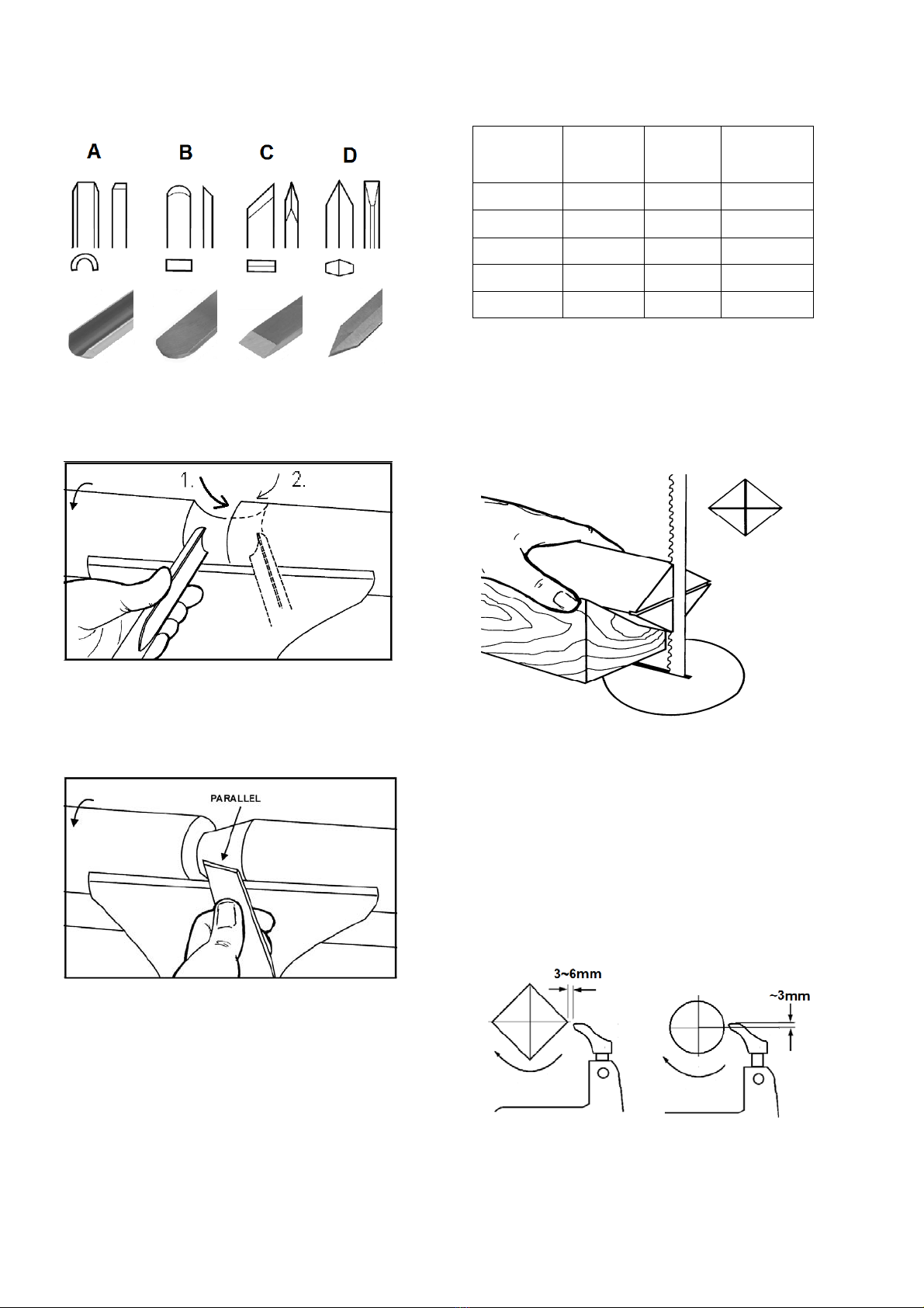
Make sure to guide and hold the chisel with both hands safe
and tight during machining.
Work only with well sharpened tools.
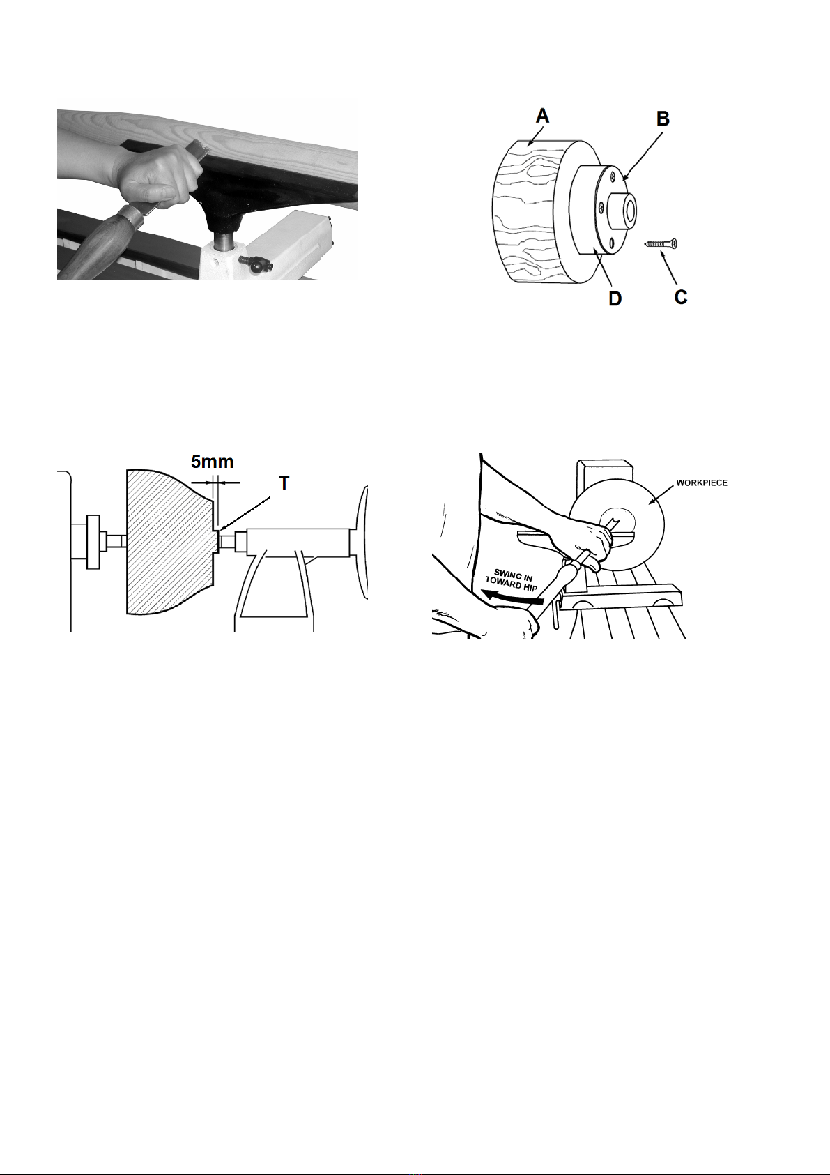
Machine only stock which is chucked securely on the
machine, always check before switching the machine on.
Provide workpieces with centre holes before clamping
between centres.
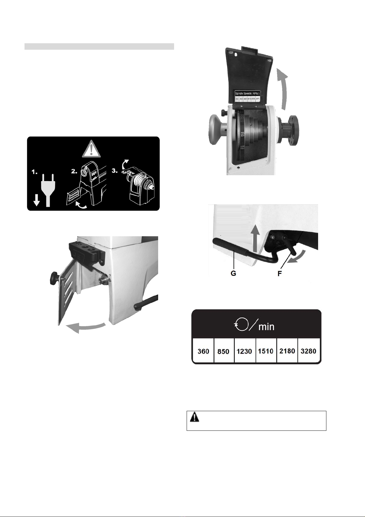
Work large and unbalanced workpieces at low spindle speed
only.
When sanding, remove the tool rest from the machine.
Workpieces with cracks may not be used.
Use homogenous workpieces only.
Check the workpiece carefully for splits, knots or other
obstructions which may cause a safety risk while turning.
Remove the chuck key or dowel pins before turning the
machine on.
Always close the belt cover.
Specifications regarding the maximum or minimum size of the
workpiece must be observed.

Test each set-up by revolving the work by hand to insure it
clears the tool rest and bed. Check setup at the lowest speed
before you increase to the operating speed.
Do not remove chips and workpiece parts until the machine is
at a standstill.
Never stop work pieces with the hand during run out.
Do not attempt to engage the spindle lock pin until the spindle
has stopped.
Never take measurements on a rotating workpiece.
Do not stand on the machine.
Connection and repair work on the electrical installation may
be carried out by a qualified electrician only.
Have a damaged or worn power cord replaced immediately.
Make all machine adjustments or maintenance with the
machine unplugged from the power source.
Make sure all levers and locking handles are tightened before
operating the lathe.
3.3 Remaining hazards
When using the machine according to regulations some
remaining hazards may still exist.
The rotating workpiece can cause injury.
Workpieces that are inhomogeneous or weak can explode
when being processed due to centrifugal force.
Only process selected woods without defects.
Unbalanced workpieces can be hazardous.
Injuries can occur when feeding tooling, if tool supports are
not correctly adjusted or if turning tools are blunt.
Risk of kickback. The tooling is caught by the rotating
workpiece and thrown back to the operator.
Thrown workpieces and workpiece parts can lead to injury.
Dust and noise can be health hazards. Be sure to wear
personal protection gear such as safety goggles and dust
mask. Use a suitable dust collection system. Work in a well-
ventilated area.
The use of incorrect mains supply or a damaged power cord
can lead to injuries caused by electricity.
4. Machine specifications
4.1 Machine description
Fig 1
Fig 2
1 Spindle handwheel
2 Index pin
3..Speed chart
4..Upper pulley cover
5 Headstock
6 Bed
7..Live centre
8 Tailstock
9 Tailstock handwheel
10 Motor
11..Belt tension lever
12 Lower pulley cover
13..Tool caddy / cord wrap
14 Face plate
15 Spur centre
16 Tool rest
17 Tool rest locking handle
18..Quill locking handle
19 Tailstock locking handle
21 On/Off switch
24 Tool rest base
25 Tool rest base locking handle
26 Belt tension release handle

4.2 Technical data
Swing over bed 318mm
Swing over tool rest base 240mm
Centre distance 500mm
Number of spindle speeds 6
360, 850, 1230, 1510, 2180, 3280 rpm
Spindle nose M33x3,5 DIN 800
Headstock spindle taper MT 2
Spindle indexing 24x15°
Spindle hole diameter 9,5mm
Tailstock spindle taper MT 2
Tailstock hole diameter 9,5mm
Tailstock ram travel 57mm
Centre above workbench 375mm
Overall (LxWxH) 853x280x450mm
Net weight 55 kg
Mains 1~230V, PE, 50Hz
Motor power 0,56kW (0,75 HP)
Reference current 2,7 A
Extension cord (H07RN-F): 3x1,5mm²
Installation fuse protection 10A
Isolation class I
4.3 Noise emission
Acoustic pressure level
(EN ISO 11202):
Idling LpA 67,4 dB(A)
In operation LpA 76,5 dB(A)
The specified values are emission levels and are not
necessarily to be seen as safe operating levels.
As workplace conditions vary, this information is intended to
allow the user to make a better estimation of the hazards and
risks involved only.
4.4 Content of delivery
Live centre
Spur centre
tooling knockout bar
Tool caddies / Cord wrap
150 mm tool rest
250 mm tool rest
75 mm face plate
Operating tools
Operating manual
Spare parts list.
Fig 3
5. Transport and start up
5.1 Transport and installation
The machine is designed to operate in closed rooms and must
be placed stable on firm and levelled surface.
For safety reasons, the machine must be bolted to the work
bench or to the optional stand.
Fig 4
For packing reasons the machine is not completely assembled
5.2 Assembly
If you notice transport damage while unpacking, notify your
supplier immediately. Do not operate the machine!
Dispose of the packing in an environmentally friendly manner.

Clean all rust protected surfaces with a mild solvent.
Install the tool caddies:
mount a tool caddy on each end of the lathe with two pan
head screws (Fig 5).
Fig 5
5.3 Mains connection
Mains connection and any extension cords used must comply
with applicable regulations.
The mains voltage must comply with the information on the
machine licence plate.
The mains connection must have a
10A surge-proof fuse.
Only use power cords marked H07RN-F
Connections and repairs to the electrical equipment may only
be carried out by qualified electricians.
5.4 Dust collection
Use a suitable dust collection and air filtration system to avoid
high dust concentrations in the air.
5.5 Starting operation
You can start the machine with the green ON-button (B, Fig
6).
Fig 6
The machine will stop when you push the red OFF-button (C).
Wait for the workpiece to come to a complete stop.
The spindle speeds are controlled by the position of the belt on
the pulleys (Fig 7).
Fig 7
6. Machine operation
6.1 Correct operating position
Always support the tool on the tool rest and guide with the
palm of your hand keeping your fingers closed.
(see Fig 8)
Fig 8
6.2 Tool selection
Successful wood turning does not result from high speeds, but
rather, from the correct use of turning tools.
A perfect and sharp wood turner tool is a precondition for
professional wood-turning.

Major tools:
Fig 9
Gouge (A, Fig 9), used for rapidly cut raw wood into round
stock, for turning bowls and plates, for turning beds, coves
and other detail (Fig 10).
Fig 10
Scraper (B, Fig 9), used for diameter scraping and to reduce
ridges.
Skew Chisel (C, Fig 9), used to make vees, beads, etc. (Fig
11). The bevel of skew is parallel to the cut.
Fig 11
Parting tool (D, Fig 9), used to cut directly into the material,
or to make a cut off. Also used for scraping and to set
diameters.
6.3 Speed selection:
Use low speeds for roughing and for large diameter work. If
vibrations occur, stop the machine and correct the cause.
Speed recommendations
Workpiece
Diameter
mm
Roughing
RPM
General
Cutting
RPM
Finishing
RPM
< 50 1510 2180 3280
50-100 850 1510 2180
100-150 850 1230 1510
150-200 360 850 1230
200-320 360 360 850
Fig 12
6.4 Turning between centres
With a ruler locate and mark the centre on each end.
Put a dimple in each end of the shock. Extremely hard woods
may require kerfs cut into the spur drive end of stock
(see Fig 13).
Fig 13
Mount the centred workpiece between the spur drive centre
and the tailstock mounted live centre
Turn the tailstock hand wheel until the live centre well
penetrates the workpiece. Reverse the hand wheel by one
quarter turn and lock the tailstock spindle.
Turn the workpiece by hand to see if it rests securely between
centres and can be rotated freely.
For turning between centres the tool rest is set approximately
3mm higher than centre line (Fig 14 and 15).
Fig 14

Fig 15
6.5 Bowl turning
Turn outside of bowl between centres.
Turn a short tenon the size of the hole in the faceplate
(T, Fig 16). This will allow centring the workpiece.
Fig 16
Mount the workpiece (A, Fig 17) directly to the face plate
using 4 wood screws (C) from the back. Be careful to use
screws short enough not to interfere with the cutting process
but long enough to hold the workpiece securely to the face
plate.
If screw mounting is not allowed at all, the work may be glued
to a backing block (D) and the backing block screwed to the
face plate. A piece of paper in the glue joint will prevent
damaging the wood when separated later.
Mount the face plate with the workpiece already attached onto
the spindle nose thread and hand tighten.
Move tailstock away, remove centre from tailstock to prevent
injury.
Turn the workpiece by hand to see if it rests securely and can
be rotated freely.
Fig 17
For face plate turning the tool rest is set slightly lower than
centre line.
Caution:
Cut with your chisel on the left side of the turning centre only.
Use left hand to control cutting edge of gouge, while right
hand swings tool handle around toward your body (Fig 18).
Fig 18
Try to make one, very light continuous movement from the rim
to the bottom of the bowl to ensure a clean, sweeping curve
through the workpiece.
Move tool support to the exterior to re-define bottom of bowl.
6.6 Sanding and Finishing
Remove the tool rest and begin with a fine grit sandpaper (120
grit) and progress through each grit, using only light pressure.
Use power sanding techniques to avoid concentric sanding
marks.
Finish sanding with 220 grit.
Apply first coat of finish. Allow to dry before sanding again
with 320 or 400 grit sandpaper.
Turn lathe back on and make a separation cut through the
base. Stop at about dia. 80mm and use a fine tooth saw to
separate the bowl from the waste.
Apply additional finish coats and allow to dry before buffing.

7. Setup and adjustments
General note:
Setup and adjustment work may only be carried out after
the machine is protected against accidental starting by
pulling the mains plug.
Make sure all levers and locking handles are tightened
before operating the lathe.
7.1 Changing spindle speed
Disconnect the machine from the power source
(unplug) !
Fig 19
Loosen the locking screw and open the lower pulley cover.
Fig 20
Loosen the locking screw and open the upper pulley cover.
Fig 21
Take tension off the belt. Pull handle (F, Fig 22) and lift the
lever (G).
Fig 22
You can now position the belt in the desired speed.
Fig 23
Make sure belt is properly seated in both pulleys.
Push lever (G) down to tighten the belt.
Close and lock the pulley covers.
WARNING
Keep pulley covers closed during operation.

7.2 Installing work holding
Disconnect the machine from the power source (unplug).
The faceplate is used for tuning bowls. There are a number
of holes for mounting the workpiece.
Make sure the two sets screws (B, Fig 24) in the face plate
have been backed out.
Push in spindle lock (A)
Thread the faceplate onto the spindle in a clockwise direction,
and tighten.
Tighten the two set screws (B).
Fig 24
Remove the faceplate by loosening the two set screws (B).
Push in the spindle lock and use the provided tool (C).
Caution: always cut with your chisel on the left half of the
workpiece only.
Never press the spindle lock while the spindle is turning!
The spur centre is used to hold workpieces between centres.
Make sure the mating surfaces are clean.
Push the spur centre into the spindle.
Fig 25
Fig 26
To remove, use the knockout bar to tap out the spur centre.
Hold spur centre to prevent it from falling (Fig 26).
The live centre is used to hold a workpiece between centres.
Make sure the mating surfaces are clean.
Push the live centre into the quill.
Fig 27
To remove, rotate handwheel counter-clockwise to retract
quill, until centre releases from quill (Fig 27).
7.3 Adjusting tool rest
Position the tool rest (C, Fig 28) as close to the workpiece as
possible. Tighten handle (A) to lock.
Fig 28

Set the height to approximately 3mm above centre. Tighten
indexable knob (B).
7.4 Adjusting tailstock
Turn the hand wheel (E, Fig 29) clockwise to move tailstock
quill forward. Lock quill with the indexable knob (D).
Fig 29
The handle (C) locks the tailstock in position on the bed.
The live centre can be ejected by turning the hand wheel
counter-clockwise.
The live centre pin can be removed to allow deep hole drilling
operations.
Caution: Do not position tailstock over the edge of bed. This
will result in less clamping surface and increase risk of injury.
7.5 Spindle index
The index feature allows you to cut evenly spaced features in
a workpiece while keeping the Lathe spindle locked.
The lathe provides 24 index positions.
These are identified by numbers on the spindle pulley (H, Fig
30).
Thread index pin (J) into the headstock. Make sure that it
locates in one of the pulley holes.
Note: A 3mm hex key (K) can be used to help tighten/loosen
the index pin.
Fig 30
Caution:
Release index pin before turning on the lathe.
Never press the index pin while the spindle is turning.
8. Maintenance and inspection
General notes:
Maintenance, cleaning and repair work may only be
carried out after the machine is protected against
accidental starting by pulling the mains plug.
Clean the machine regularly (wear eye and dust protection)
Inspect the proper function of the dust collection.
Protect headstock spindle, tailstock quill, tool rest post and
machine bed from rust, by applying thin coat of oil or rust
protectorant.
Defective safety devices must be replaced immediately.
Repair and maintenance work on the electrical system may
only be carried out by a qualified electrician
8.1 Adjusting bed clamping
If adjustment is needed, slide the tailstock or toolrest to the
edge of the bed and slightly turn the cam lock nut (B, Fig 28).
Test the clamping function and repeat if necessary.
Fig 31
8.3 Changing belt
Disconnect the machine from the power source
(unplug) !
Open the pulley covers and remove the Poly-V belt from the
lower pulley.
Loosen two set screws (B, Fig 33) and unscrew the hand
wheel (A).
Note: Left hand thread, turn clockwise to remove.
Loosen two set screws (C) in spindle pulley.

Fig 33
Remove bearing cover (D, Fig 34).
Note: Spindle lock (E) and spring will pop out.
Fig 34
Use a rubber mallet, to tap the spindle towards tailstock.
(also can use a piece of hard wood, or brass to protect the
spindle).
Fig 35
Go only far enough to remove the belt.
Fig 36
To reassemble reverse the procedure.
Note:
To avoid bearing overload, do not over tighten the handwheel.
Thread it on to the spindle until its snug, then back off slightly
and tighten the grub screws.
9. Trouble shooting
Motor fails to develop full power
*Power line overloaded-
Correct overload condition.
*Undersized wires in power supply system-
Increase supply wire size.
Motor or spindle stalls or doesn’t start
*No electricity-
check mains and fuse.
*Defective switch, motor or cord-
consult an electrician.
*Excessive cut-
Reduce depth of cut.
*Improper belt tension or worn belt-
Adjust or replace belt as needed
Machine vibrates excessively
*Stands on uneven surface-
adjust stand for even support.
*Workpiece is not properly centred
*The speed is too high
*Motor mounting fasteners are loose
Tailstock moves when applying pressure
*Cam lock nut needs adjusting-
Tighten cam lock nut (see chapter 8.1)
*Bed and tailstock surfaces are greasy-
Clean surface and re-apply rust protection

10. Environmental protection
Protect the environment.
Your appliance contains valuable materials which can be
recovered or recycled. Please leave it at a specialized
institution.
This symbol indicates separate collection for electrical and
electronic equipment required under the WEEE Directive
(Directive 2012/19/EC) and is effective only within the
European Union.
11. Accessories
Stock number 719201
Bed Extension 560mm (Fig 37)
Fig 37
Stock number 719202
Machine stand (Fig 38, Fig 39)
Fig 38
Fig 39
Overall dimensions, machine with stand
Stock number 719203
Machine stand extension 560mm (Fig 40)
Fig 40
Refer to the JET-Pricelist
for various tools and work holding.

DE - DEUTSCH
Betriebsanleitung
Sehr geehrter Kunde,
vielen Dank für das Vertrauen, welches Sie uns beim Kauf Ihrer neuen JET-Maschine entgegengebracht haben. Diese Anleitung
ist für den Eigentümer und die Bediener zum Zweck einer sicheren Inbetriebnahme, Bedienung und Wartung der JET
Drechselbank JWL-1221-M erstellt worden. Beachten Sie bitte die Informationen dieser Gebrauchsanleitung und der
beiliegenden Dokumente. Lesen Sie diese Anleitung vollständig, insbesondere die Sicherheitshinweise, bevor Sie die Maschine
zusammenbauen, in Betrieb nehmen oder warten. Um eine maximale Lebensdauer und Leistungsfähigkeit Ihrer Maschine zu
erreichen befolgen Sie bitte sorgfältig die Anweisungen.
Inhaltsverzeichnis
1. Konformitätserklärung
2. Garantie
3. Sicherheit
Bestimmungsgemäße Verwendung
Allgemeine Sicherheitshinweise
Restrisiken
4. Maschinenspezifikationen
Maschinenbeschreibung
Technische Daten
Schallemission
Lieferumfang
5. Transport und Inbetriebnahme
Transport und Aufstellung
Montage
Netzanschluss
Absaug Anschluss
Inbetriebnahme
6. Maschinenbetrieb
Richtige Arbeitsstellung
Drehstahl Auswahl
Drehzahlwahl
Drechseln zwischen Spitzen
Drechseln von Schalen und Tellern
Schleifen und Imprägnieren
7. Rüst und Einstellarbeiten
Wechseln der Drehzahl
Spannmittel Montage
Anpassung der Handstahlauflage
Anpassung des Reitstocks
Spindel Teileinrichtung
8. Wartung und Inspektion
Klemmexzenter-Einstellung
Riemenwechsel
9. Störungsabhilfe
10. Umweltschutz
11. Zubehör
1. Konformitätserklärung
Wir erklären in alleiniger Verantwortlichkeit, dass dieses
Produkt mit den auf Seite 2 angegebenen Richtlinien
übereinstimmt.
2. Garantie
TOOL France SARL garantiert, dass das gelieferte Produkt
frei von Material- und Fertigungsfehlern ist. Diese Garantie
trifft nicht auf jene Defekte zu, welche auf direkten oder
indirekten, nicht fachgerechten Gebrauch, Unachtsamkeit,
Unfallschaden, Reparatur, mangelhafte Wartung bzw.
Reinigung sowie normalen Verschleiß zurückzuführen sind.
Die ausführlichen Garantieleistungen (z.B.
Gewährleistungsfrist) sind den Allgemeinen
Geschäftsbedingungen (AGB) zu entnehmen. Die AGB sind
auf der Internetseite ihres Händlers einzusehen oder werden
auf Anfrage per Post zugestellt.
TOOL France SARL behält sich das Recht vor, jederzeit
Änderungen am Produkt und Zubehör vorzunehmen.
3. Sicherheit
3.1 Bestimmungsgemäße Verwendung
Diese Drechselbank ist ausschließlich zum Drechseln von
Holz geeignet.
Die Bearbeitung anderer Werkstoffe ist nicht zulässig bzw.
darf in Sonderfällen nur nach Rücksprache mit dem
Maschinenhersteller erfolgen.
Es dürfen nur Werkstücke bearbeitet werden welche sicher
zugeführt und gespannt werden können.
Die bestimmungsgemäße Verwendung beinhaltet auch die
Einhaltung der vom Hersteller angegebenen Betriebs- und
Wartungsanweisungen.
Die Maschine darf ausschließlich von Personen bedient
werden, die mit Betrieb und Wartung vertraut und über die
Gefahren unterrichtet sind.
Das gesetzliche Mindestalter ist einzuhalten.
Die Maschine nur in technisch einwandfreiem Zustand
benützen.
Beim Arbeiten an der Maschine müssen alle
Sicherheitsvorrichtungen angebracht sein.
Neben den in der Gebrauchsanleitung enthaltenen
Sicherheitshinweisen und den besonderen Vorschriften Ihres
Landes sind die für den Betrieb von
Holzbearbeitungsmaschinen allgemein anerkannten
fachtechnischen Regeln zu beachten.
Jeder darüber hinaus gehende Gebrauch gilt als nicht
bestimmungsgemäß und für daraus resultierende Schäden
haftet der Hersteller nicht. Das Risiko trägt allein der
Benutzer.

3.2 Allgemeine Sicherheitshinweise
Holzbearbeitungsmaschinen können bei unsachgemäßem
Gebrauch gefährlich sein. Deshalb ist zum sicheren Betreiben
die Beachtung der zutreffenden Unfallverhütungs-
Vorschriften und der nachfolgenden Hinweise erforderlich.
Lesen und verstehen Sie die komplette Gebrauchsanleitung
bevor Sie mit Montage oder Betrieb der Maschine beginnen.
Bewahren Sie die Bedienungsanleitung, geschützt vor
Schmutz und Feuchtigkeit, bei der Maschine auf, und geben
Sie sie an einen neuen Eigentümer weiter.
An der Maschine dürfen keine Veränderungen, An- und
Umbauten vorgenommen werden.
Überprüfen Sie täglich vor dem Einschalten der Maschine die
einwandfreie Funktion und das Vorhandensein der
erforderlichen Schutzeinrichtungen.
Festgestellte Mängel an der Maschine oder den
Sicherheitseinrichtungen sind zu melden und von den
beauftragten Personen zu beheben.
Nehmen Sie die Maschine in solchen Fällen nicht in Betrieb,
sichern Sie die Maschine gegen Einschalten durch Ziehen des
Netzsteckers.
Zum Schutz von langem Kopfhaar Mütze oder Haarnetz
aufsetzen.
Enganliegende Kleidung tragen, Schmuck, Ringe und
Armbanduhren ablegen.
Tragen Sie Schutzschuhe, keinesfalls Freizeitschuhe oder
Sandalen.
Verwenden Sie die durch Vorschriften geforderte persönliche
Schutzausrüstung.
- Augenschutz
- Ohrenschutz
- Staubschutz
Beim Arbeiten an der Maschine keine Handschuhe tragen.
Die Maschine so aufstellen, dass genügend Platz zum
Bedienen und zum Führen der Werkstücke gegeben ist.
Sorgen Sie für gute Beleuchtung.
Achten Sie darauf, dass die Maschine standsicher auf fester
und ebener Tischfläche steht.
Beachten Sie dass die elektrische Zuleitung nicht den
Arbeitsablauf behindert und nicht zur Stolperstelle wird.
Den Arbeitsplatz frei von behindernden Werkstücken, etc.
halten.
Seien Sie aufmerksam und konzentriert. Gehen Sie mit
Vernunft an die Arbeit.
Achten Sie auf ergonomische Körperhaltung.
Sorgen Sie für sicheren Stand und halten Sie jederzeit das
Gleichgewicht.
Arbeiten Sie niemals unter dem Einfluss von Rauschmitteln
wie Alkohol und Drogen an der Maschine. Beachten Sie, dass
auch Medikamente Einfluss auf Ihr Verhalten nehmen
können.
Niemals in die laufende Maschine greifen.
Halten Sie Unbeteiligte, insbesondere Kinder vom
Gefahrenbereich fern.
Die laufende Maschine nie unbeaufsichtigt lassen.
Vor dem Verlassen des Arbeitsplatzes die Maschine
ausschalten.
Benützen Sie die Maschine nicht in der Nähe von brennbaren
Flüssigkeiten oder Gasen.
Beachten Sie die Brandmelde- und
Brandbekämpfungsmöglichkeiten z.B. Standort und
Bedienung von Feuerlöschern.
Benützen Sie die Maschine nicht in feuchter Umgebung und
setzen Sie sie nicht dem Regen aus.
Achten Sie stets darauf, dass keine zu große
Staubkonzentration entsteht – verwenden Sie stets eine
geeignete Absauganlage
Holzstaub ist explosiv und kann gesundheitsschädigend sein.
Insbesondere tropische Hölzer und harte Hölzer wie Buche
und Eiche sind als krebserregend eingestuft.
Vor der Bearbeitung Nägel und andere Fremdkörper aus dem
Werkstück entfernen.
Es ist darauf zu achten dass das Drechselwerkzeug beim
Bearbeiten mit beiden Händen sicher gehalten und sicher
geführt wird.
Nur mit gut geschärften Werkzeugen arbeiten.
Bearbeiten Sie nur ein Werkstück, das sicher eingespannt ist.
Vor dem Einschalten immer prüfen.
Werkstücke vor dem Spannen zwischen Spitzen beidseitig mit
Zentrierbohrung versehen.
Große und unwuchtige Werkstücke nur mit kleiner Drehzahl
bearbeiten.

Bei Schleifarbeiten die Handstahlauflage entfernen.
Nur homogene Werkstücke bearbeiten.
Prüfen Sie das Werkstück sorgfältig auf Risse, lose Äste oder
andere Abweichungen welche eine Gefährdung darstellen.
Spannschlüssel oder Spannstifte vor dem Einschalten der
Maschine entfernen.
Riemenabdeckung immer schließen.
Angaben über die min. und max. Werkstückabmessungen
müssen eingehalten werden
Drehen Sie nach jeder Aufspannung das Werkstück von Hand
und prüfen Sie die sichere Aufspannung und freie Rotation.
Starten Sie die Maschine in der niedrigsten Drehzahlstufe.
Späne und Werkstückteile nur bei stehender Maschine
entfernen.
Auslaufende Werkstücke nie von Hand abbremsen.
Die Spindelblockierung nur bei stehender Spindel betätigen.
Messungen nie am rotierenden Werkstück vornehmen.
Nicht auf der Maschine stehen.
Arbeiten an der elektrischen Ausrüstung der Maschine dürfen
nur durch eine Elektrofachkraft vorgenommen werden.
Tauschen Sie ein beschädigtes Netzkabel sofort aus.
Umrüst-, Einstell- und Reinigungsarbeiten nur im
Maschinenstillstand und bei gezogenem Netzstecker
vornehmen.
Kontrollieren Sie vor jedem Maschinenstart, dass alle Griffe
und Hebel festgesetzt sind.
3.3 Restrisiken
Auch bei vorschriftsmäßiger Benutzung der Maschine
bestehen die nachfolgend aufgeführten Restrisiken.
Verletzungsgefahr durch das frei drehende Werkstück.
Nicht homogene bzw. nicht belastbare Werkstücke können
auf Grund der Zentrifugalkraft explodieren.
Verarbeiten Sie nur ausgesuchte Hölzer ohne Fehler.
Unwuchtige Werkstücke führen zu Verletzungsgefahr.
Verletzungsgefahr durch unsichere Werkzeugführung, bei
nicht exakt angestellter Werkzeugauflage und stumpfem oder
defektem Drechselwerkzeug.
Rückschlaggefahr. Das Werkzeug wird von dem sich
drehenden Werkstück erfasst und gegen den Bediener
geschleudert.
Gefährdung durch wegfliegende Werkstücke und
Werkstückteile.
Gefährdung durch Lärm und Staub.
Unbedingt persönliche Schutzausrüstungen wie Augen-,
Gehör- und Staubschutz tragen.
Eine geeignete Absauganlage einsetzen. Sorgen Sie für gute
Durchlüftung.
Gefährdung durch Strom, bei nicht ordnungsgemäßer
Verkabelung.
4. Maschinenspezifikation
4.1 Maschinenbeschreibung
Fig 1
Fig 2
1 Spindel Handrad
2 Spindel Teileinrichtung
3..Drehzahl Schild
4..Oberer Riemendeckel
5 Spindelstock
6 Maschinenbett
7..Rollkörner

8 Reitstock
9 Reitstock Handrad
10 Motor
11..Riemenspanner
12 Unterer Riemendeckel
13..Werkzeugablage / Kabelspeicher
14 Aufspannscheibe
15 Stirnmitnehmer
16 Handstahlauflage
17 Handstahlauflage-Klemmung
18..Reitstockpinole-Klemmung
19 Reitstock Klemmhebel
21 Ein/ Aus Schalter
24 Handstahlauflagenbasis
25 Handstahlauflagenbasis-Klemmhebel
26 Riemenentspanner
4.2 Technische Daten
Drehdurchmesser über Bett 318mm
Drehdurchmesser über Handstahlauflage 240mm
Spitzenweite 500mm
Anzahl mechanischer Geschwindigkeiten 6
360, 850, 1230, 1510, 2180, 3280 U/min
Spindelnase M33x3,5 DIN 800
Spindelkonus MK2
Spindelteilung 24x15°
Spindelbohrung 9,5mm
Reitstockkonus MK2
Reitstockbohrung 9,5mm
Reitstock Pinolenhub 57mm
Spitzenhöhe über Werkbank 375mm
Maschinenabmessungen (LxTxH) 853x280x450mm
Nettogewicht 55 kg
Netzanschluss 1~230V, PE, 50Hz
Motorleistung 0,56 kW (0,75 PS)
Betriebsstrom 2,7 A
Verlängerungskabel (H07RN-F): 3x1,5 mm²
Bauseitige Absicherung 10A
Isolationsklasse I
4.3 Schallemission
Schalldruckpegel
(nach EN ISO 11202):
Leerlauf LpA 67,4 dB(A)
Bearbeitung LpA 76,5 dB(A)
Die angegebenen Werte sind Emissionspegel und sind nicht
notwendigerweise Pegel für sicheres Arbeiten.
Sie sollen dem Anwender eine Abschätzung der Gefährdung
und des Risikos ermöglichen.
4.4 Lieferumfang
Mitlaufkörnerspitze
Stirnmitnehmer
Ausstoßbolzen
Werkzeugablage / Kabelspeicher
150 mm Handstahlauflage
250mm Handstahlauflage
75 mm Aufspannscheibe
Bedienwerkzeug
Gebrauchsanleitung
Ersatzteilliste.
Fig 3
5. Transport und Inbetriebnahme
5.1 Transport und Aufstellung
Die Aufstellung der Maschine sollte in geschlossenen
Räumen erfolgen, die Aufstellfläche muss dabei ausreichend
eben und belastungsfähig sein.
Um einen sicheren Betrieb der Maschine zu gewährleisten,
muss sie auf der Werkbank oder dem optional erhältlichen
Untersatz festgeschraubt sein.
Fig 4
Aus verpackungstechnischen Gründen ist die Maschine nicht
komplett montiert.

5.2 Montage
Falls Sie beim Auspacken Transportschäden bemerken,
informieren Sie den Zulieferer hierüber unverzüglich. Nehmen
Sie die Maschine auf keinen Fall in Betrieb!
Entsorgen Sie die Verpackung auf eine umweltfreundliche Art.
Reinigen Sie alle vor Rost geschützten Oberflächen mit einem
milden Lösungsmittel.
Montage der Werkzeugablagen:
Befestigen Sie an jedem Bettende die Werkzeugablage mit
zwei Linsenkopfschrauben (Fig 5).
Fig 5
5.3 Netzanschluss
Der kundenseitige Netzanschluss sowie die verwendeten
Verlängerungsleitungen müssen den Vorschriften
entsprechen.
Die Netzspannung und Frequenz müssen mit den
Leistungsschilddaten an der Maschine übereinstimmen.
Die bauliche Absicherung muss dabei 10A betragen.
Verwenden Sie nur Anschlussleitungen mit Kennzeichnung
H07RN-F
Anschlüsse und Reparaturen der elektrischen Ausrüstung
dürfen nur von einen Elektrofachkraft durchgeführt werden.
5.4 Absaug Anschluss
Vermeiden Sie eine hohe Luftstaubkonzentration. Setzen Sie
ein geeignetes Absaug- bzw. Filtersystem ein.
5.5 Inbetriebnahme
Mit dem grünen Eintaster (B, Fig 6) kann die Maschine
gestartet werden.
Fig 6
Zum Stillsetzen drücken Sie den Roten Aus-Taster (C).
Warten Sie bis das Werkstück zum Stillstand kommt.
Es stehen 6 Drehzahlen durch Riemenumlegen zur Verfügung
(Fig 7).
Fig 7
6. Betrieb der Maschine
6.1 Richtige Arbeitsstellung
Das Drechselwerkzeug immer aufgelegt an der
Handstahlauflage führen. Dabei die Finger geschlossen halten
und mit dem Handballen an der Handstahlauflage abstützen
(siehe Fig 8).
Fig 8

6.2 Drehstahl Auswahl
Erfolgreiches Drechseln hängt nicht von hohen Drehzahlen
ab, sondern von der richtigen Anwendung der
Drechselwerkzeuge.
Eine Voraussetzung für fachgerechtes Drechseln ist ein
einwandfreies und geschärftes Drechselwerkzeug.
Die wichtigsten Drechselstähle:
Fig 9
Drechselröhre (A, Fig 9)
Wichtigstes Drechselwerkzeug, wird verwendet zur
Schruppzerspanung, zum Aushöhlen von Schalen und Tellern
und zum Drechseln von Einschnürungen
(Fig 10).
Fig 10
Schaber (B, Fig 9)
Wird verwendet zur Außen- und Innenkalibrierung sowie zum
Entfernen von Bearbeitungsriefen.
Schrägmeißel (C, Fig 9)
Wird verwendet zum Drechseln von V-Rillen und zur
Außenkalibrierung.
Die Schneide wird parallel zum Schnitt angestellt
(Fig 11)
Fig 11
Abstechstahl (D, Fig 9) Wird verwendet um direkt in das
Werkstück einzutauchen, z.B. beim Einstechen auf Mass,
Hinterdrehen, und Abstechen.
Kann auch als Schaber eingesetzt werden.
6.3 Drehzahlwahl:
Große und unwuchtige Werkstücke nur mit kleiner Drehzahl
bearbeiten.
Beim Auftreten von Vibrationen die Maschine stoppen und
Abhilfe schaffen.
Drehzahlempfehlung in U/min (RPM)
Werkstück-
durchmesser
mm
Schruppen
U/min
Allgemeine
Schnitte
U/min
Schlichten
U/min
< 50 1510 2180 3280
50-100 850 1510 2180
100-150 850 1230 1510
150-200 360 850 1230
200-320 360 360 850
Fig 12
6.4 Drechseln zwischen Spitzen
Markieren und körnen Sie die Werkstückmitte an beiden
Enden.
Bei harten Hölzern kann es spindelstockseitig erforderlich sein
Einschnitte anzubringen (siehe Fig 13).
Table of contents
Languages:
Other Jet Lathe manuals

Jet
Jet JWL-1221VS-M User manual

Jet
Jet GHB-1330 User manual

Jet
Jet BP-1248H Service manual

Jet
Jet JWL-1015VS Service manual

Jet
Jet JML-1014VS User manual

Jet
Jet 719201 Datasheet

Jet
Jet Revelation Reverb V2.0 User manual

Jet
Jet 708358 Service manual

Jet
Jet Elite EGH-1880 Service manual

Jet
Jet JML-1014VSI User manual