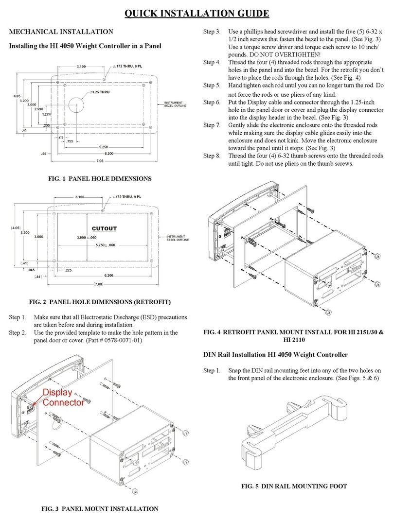
Hardy Process Solutions HI 4050 Specification sheet

PROVIDING SOLUTIONS IN:
Process Weighing
Vibration Monitoring
Local Field Service
___________________________________________________________________________________
9440 Carroll Park Dr. · Suite 150 · San Diego, CA 92121-5201· 858/278-2900 ·
800/821-5831 Fax 858/278-6700 · Web www.hardysolutions.com
TECHNICAL NOTE
Setup and Test the Analog Output on the HI 4050 unit
The purpose of this technical note is to guide the user through the setup, testing and
calibration, if necessary, of the Analog output option on the HI 4050 unit.
This setup can be performed either through the front keypad or the online browser. These
instructions will not differentiate between the two methods.
The analog output option on the HI 4050 unit has four channels. The first and third
channels are a voltage output and the second and fourth channels are current output.
Each channel is independent from the other channels.
Setup:
OUTPUTS:
Default outputs are:
Channel 1: 0-10 V
Channel 2: 4-20 mA
Channel 3: 0-10 V
Channel 4: 4-20 mA
Each of the analog output channels allows the user to change the output range of the
channel. So the channels can be changed to be anywhere from x to y, where x is the low
output (range 0-10 V or 0-20 mA) and y is the high output (range 0-10 V or 0-20 mA).
Examples:
Channel 1: 0-5 V;
Channel 2: 0-20 mA;
Channel 3: 10-0 V; (note the reverse output levels.)
Channel 4: 4-12 mA;
INPUTS:
Default inputs are: 0-100 for all channels.

PROVIDING SOLUTIONS IN:
Process Weighing
Vibration Monitoring
Local Field Service
___________________________________________________________________________________
9440 Carroll Park Dr. · Suite 150 · San Diego, CA 92121-5201· 858/278-2900 ·
800/821-5831 Fax 858/278-6700 · Web www.hardysolutions.com
The range of the inputs allowed is virtually unlimited; however, even though the outputs
can be ranged in reverse order, to operate correctly, the input HIGH value must be higher
than the input LOW setting.
Operation:
The output range will be applied relative to the input range. The output to input scaling
will be linear.
So if the input equals the LOW input setting, the LOW output will be outputted.
If the input equals the HIGH input setting, the HIGH output will be outputted.
If the input equals the mid-point between the LOW and HIGH input settings, the output
will be the midpoint between the LOW and HIGH output values.
The inputs for the analog outputs must be mapped. The mapping of the analog inputs
will determine where the input value will come from. This could be a weight reading,
scratchpad value, network input register, or any other value from a mapped location.
Setup:
Set the OUTPUT LOW and HIGH settings to be the limits you wish to have within the
limitations of the channels.
Voltage channels limits 0-10 V.
Current channels limits 0-20 mA.
Set the input LOW and HIGH settings to be the limits you wish to have the analog
outputs react to.
Mapping:
Simple mapping of either the gross or net weight to the analog output channel can be
performed from the front keypad.
Mapping from any source other than the weight reading should be done on the browser
mapping page.
Simple mapping (steps are through front keypad, but can be done on mapping page):
1. Enter the setup menu;
2. Scroll down to the ‘MAP’ menu, enter;
3. Scroll down to ‘Dest’ (destination);
4. Use the right/left arrow keys to scroll through the destination mapping terms to
find the analog output channel you wish to map. This also shows the mapping
term for that channel. Example: ‘Dest Analog2 HFO29’ is selection for analog
output channel 2. Mapping term is HFO29.
5. Press enter to accept this destination.

PROVIDING SOLUTIONS IN:
Process Weighing
Vibration Monitoring
Local Field Service
___________________________________________________________________________________
9440 Carroll Park Dr. · Suite 150 · San Diego, CA 92121-5201· 858/278-2900 ·
800/821-5831 Fax 858/278-6700 · Web www.hardysolutions.com
6. Verify the mapping term in the ‘Map Dest’ line shows the term for the destination
you chose.
7. Scroll down to ‘Src’ (source);
8. Use the right/left arrow keys to scroll through the source mapping terms available
for mapping in this manner. This may be limited to gross and net weight. If your
source is not present in this list, you should do the mapping through the browser
pages. If your source is present, stop at its selection.
9. Press enter to accept this source.
10. Verify the mapping term in the ‘Map Src’ line shows the term for the source you
chose.
11. Scroll down to ‘Add Map’ and verify your destination and source are listed as the
mapping equation to map. If present, press enter.
12. Scroll down to the ‘MAP’ line in this menu. Your mapping equation should now
show up in the ‘MAP’ line. If there are multiple mapping equations present in the
unit, you can press the right/left arrow keys to scroll through the mapping
equations.
Complex mapping (Any mapping that requires input other than single weight):
This mapping should be done from the browser mapping page.
1. Open the browser and go to the mapping page.
2. Open the drop down list under the Destination>Control;
3. Scroll down and highlight/click on the Analog Card Output channel you wish to
map to.
4. Click on the ‘Select’ button.
5. You should see your mapping term followed by the ‘=’ sign entered into the
window next to the ‘map’ button lower down on the page.
6. Open the drop down list under the source that would hold the source you wish to
select. This may be a Network input, a Process Data input, Control, or even a
Scratchpad input.
NOTE: You may even use the destination selections as a source.
7. Once you have found and highlight/click on your source selection, click on the
Select button.
If you cannot find your desired source in any of the drop down lists, you can open
the list of mapping symbols, using the link found above the mapping equations. If
you find the source in the list of mapping symbols, you may type the mapping
term into the window to complete the equation. NOTE: The mapping terms must
be typed in upper case letters to be accepted.
8. You should see your mapping term for the source selected completing the
equation in the window next to the ‘Map’ button.
9. Click on the ‘Map’ button.
10. Verify your equation now shows up under the “Map:” section where it shows all
the mapped equations.

PROVIDING SOLUTIONS IN:
Process Weighing
Vibration Monitoring
Local Field Service
___________________________________________________________________________________
9440 Carroll Park Dr. · Suite 150 · San Diego, CA 92121-5201· 858/278-2900 ·
800/821-5831 Fax 858/278-6700 · Web www.hardysolutions.com
Testing:
Setting up the test for the analog output:
There are three methods to check if the output from the analog output channel is correct:
The loop back value shown on the analog output setup page;
See the results on the receiving end of the analog output;
Measure the output with a meter.
The loop back value shown will be a close result of the actual output, but this is low
resolution and may have some error in the actual output.
Checking the results on the receiving end of the analog output is a good way to find if
both the unit settings and the receiver settings match. However, if an adjustment needs to
be made to the output, trying to determine how much to adjust can be difficult.
Checking the output with a meter gives you an actual reading and can be used as specific
values to use in the event an adjustment needs to be made.
Testing:
Following the mapping instructions through the browser, map a scratchpad to the analog
output channel you wish to test.
Once you have the scratchpad mapped to the channel, you can then change the value in
the scratchpad register, located towards the bottom of the mapping page in the browser.
This value can be varied from the minimum input value set for the analog output, to the
maximum value, or any value between the two limits.
The analog output channel should react to this input with the proper output. It is now
very simple to enter the minimum input value and see if the output matches what the
settings indicate. That is, if the input low is 0 and the output range is 0 to 10 v, then the
output should show 0 v.
This also applies for the maximum. Set the input high value into the scratchpad and see
if the output is 10 v (per our example).
This can be used to check the linearity of the out as well by entering other values into the
scratchpad, like 20%, or 50%, etc of the input range and check to see if the output
response properly.
NOTE: The method can also be checked using the method of reading the loop back value
on the analog output page of the browser as well as using the receiver value.
Once you have completed your testing, you would need to reset your mapping to the
desired analog inputs.

PROVIDING SOLUTIONS IN:
Process Weighing
Vibration Monitoring
Local Field Service
___________________________________________________________________________________
9440 Carroll Park Dr. · Suite 150 · San Diego, CA 92121-5201· 858/278-2900 ·
800/821-5831 Fax 858/278-6700 · Web www.hardysolutions.com
Calibration, (applies to the HI 4050 and HI 4060 units):
On some occasions the output from the analog output channel is slightly off from the
expected output. If this is the case, there is a method for the HI 4000 series units to re-
calibrate the analog outputs.
If the testing shows the output is not quite correct for input, the analog output can be
calibrated. The following steps provide the method for the recalibration of the channel.
1. Set up the analog output in a manner to allow the user to see the output results at
two different points in the output range. The easiest way would be to set up
mapped to a scratchpad and running the test.
2. Set an input value to the channel. This would normally be the Input Low value.
3. Measure and record the actual output from that channel.
4. Set higher input value to the channel. This would normally be the Input High
value.
5. Measure and record the actual output from that channel.
6. On the analog output setup page in the browser, click on the right blue arrow
towards bottom of the page. This will open the Analog Output Calibration page.
7. On lower half of the page, select the channel you tested.
8. Enter the desired output value you wished to see when you entered your higher
value.
9. Enter the actual output value you measured with the higher input.
10. Enter the desired output value you wished to see when you entered your lower
value.
11. Enter the actual output value you measured with the lower input.
12. Click on the “Recalibrate” button. This will then recalibrate the channel.
13. Click on the “Save parameters” button to save the changes.
14. Retest your analog channel for proper outputs per the input values.
15. Repeat these steps for each channel you need to recalibrate.
Example:
Channel two setup is:
Output Low: 4 mA
Output High: 20 mA
Input Low: 0
Input High: 100
Test results:
Input 0 has output 4.12 mA
Input 50 has output 12.3 mA

PROVIDING SOLUTIONS IN:
Process Weighing
Vibration Monitoring
Local Field Service
___________________________________________________________________________________
9440 Carroll Park Dr. · Suite 150 · San Diego, CA 92121-5201· 858/278-2900 ·
800/821-5831 Fax 858/278-6700 · Web www.hardysolutions.com
Setup for the recalibration:
As shown, the expected outputs of 4.00 and 12.00 are entered as the desired outputs.
The actual outputs measured at the two points are then entered as well.
Clicking on the “Recalibrate” button will cause the unit to adjust the analog outputs so
the actual outputs should match the desired outputs.
A retest would be recommended.
Normally only a single recalibration is needed on a channel. However, if the output is
greatly off from the expected output, multiple checks may be needed to get it fine tuned.
Dec. 2017
Table of contents
Other Hardy Process Solutions Controllers manuals
Popular Controllers manuals by other brands

Eurotherm
Eurotherm 2132 operating instructions

Chromalox
Chromalox Chroma-FP-OD Series Installation and operating manual

Atlas Copco
Atlas Copco EBL Drive Configuration manual
Desoutter
Desoutter ESP1-A Original instructions
PMA
PMA KS 45 manual

Equalizer Systems
Equalizer Systems Auto Level Basic Troubleshooting
