Harken Industrial CMC CLUTCH Installation instructions

Inspection Procedure
CMC CLUTCH™ by Harken Industrial™
1
Purpose / Intent
This procedure outlines the relevant checks of a detailed inspection for Personal Protective Equipment (PPE).
The detailed inspection should be performed at least once every 12 months and after any exceptional event(s)
that may occur during use of the product.
The inspector should be a competent person and have read and understood all parts of the Inspection
Procedure, Periodic PPE Inspection Form and User Manual.
The inspector should also stay informed of any changes to inspection requirements, the product and any related
recalls, and this documentation.
Required Materials to Perform the Inspection
CLUTCH User Manual
CLUTCH Periodic PPE Inspection Form
CLUTCH Inspection Procedure (this document)
A new, unused CLUTCH for comparison
2m of rope within the acceptable parameters for the CLUTCH (see inside of Moving Side Plate or CLUTCH User
Manual)
Documentation of product history from the user
Product History
The user should provide information regarding the lifecycle of the device. Of special importance are:
Date of purchase.
Date of first use.
Usage conditions and amount of use.
Reports on any exceptional event that the device may have experienced. Exceptional events include the
following:
oDynamic events such as falls or fall arrest
oOverloading or improper use cases
oImproper storage, cleaning or transport
oModifications made by parties other than the manufacturer
oOther exceptional events
Any PPE exhibiting unexpected wear or degradation must be quarantined and undergo a detailed inspection.

Inspection Procedure
CMC CLUTCH™ by Harken Industrial™
2
1. Visual Inspection
Ensure the presence and legibility of the device markings.
Ensure that the product number is located and is legible on the backside of the Chassis in the area covered
by the Control Handle when it is in the Stop position.
Ensure that the CE certification mark is located and is legible on the inside surface of the Moving Side Plate.
Visually compare the device with a new device and check to make sure that there are no missing or modified
parts.
Carefully inspect the entire device for signs of damage such as dents, deep scratches, cracks, yielding or
excessive wear. Check for any sharp edges, especially in the areas of the rope path. Take extra care to
inspect attachment points such as the Attachment Eye and the Becket for signs of damage or deformation.
Inspect the Sheave, Tension Rope Guide, and Friction Shoe for wear. The Tension Rope Guide and Friction
Shoe are shown in blue and the Sheave wear indicators (3) are shown in orange in the images below.

Inspection Procedure
CMC CLUTCH™ by Harken Industrial™
3
If the wear indicators have been worn away, the unit must be retired.
2. Functional Checks
2.1 Sheave Movement
Open the device and perform the following checks on the Sheave:
Ensure that the Sheave is able to rotate anti-clockwise and emits an audible clicking sound.
Check that the Sheave is not able to rotate clockwise.
Check that the Sheave is firmly attached to the Sheave Swing Arm without excessive axial movement,
i.e. >2mm.
2.2 Sheave Swing Arm Movement
With the device open, start with the Control Handle in the Stop position. Press the Sheave into the pinch
area and check that the Sheave is able to swing into the Chassis and make contact with the stainless
steel Friction Shoe.
Release the Sheave and move the Control Handle to the Stand By position while observing the position
of the Sheave and Sheave Swing Arm. The Sheave and Sheave Swing Arm should move to the left,
rotating anticlockwise until the rope-path laser etching becomes visible on the inner surface of the
Chassis.
With the Control Handle in the Stand By position, press on the Sheave and check that the Sheave is able
to swing into the Chassis and make contact with the stainless steel Friction Shoe.
Check that the Sheave Swing Arm is firmly attached to the Chassis and inspect the rivet on both sides for
damages.

Inspection Procedure
CMC CLUTCH™ by Harken Industrial™
4
2.3 Control Handle Movement
With the device closed, rotate the Control Handle through its range of motion from Stop to Anti-panic,
ensuring there is no excessive drag.
Rotate the Control Handle to the Stand By position and feel for a well-defined holding force at Stand By.
Rotate the device back and forth in this configuration and check that the Control Handle stays in the
Stand By position.
Hold the device in the left hand with the Moving Side Plate facing the palm. Use your fingers to press
the Sheave into the Chassis. While holding the Sheave into the Chassis, use your right hand to rotate the
Control Handle from Stand By to Release (Range) position. Continue to rotate the Control Handle
through the Release (Range) position and check that this action drives the Sheave away from the
Chassis, i.e. overcomes the pressure applied with the left hand.
Continue to rotate the Control Handle beyond the Release (Range) position while maintaining pressure
on the Sheave with the left hand until the Anti-panic position is reached. Check that the Sheave releases
and is once again able to be pressed into the Chassis.
Inspect the rivet in the center of the Control Handle for damage.
Ensure that the Control Handle is firmly attached to the Chassis and has minimal clearance with the
Chassis.
2.4 Side Plate Release Latch and Moving Side Plate Movement and Function
2.5 Check the Side Plate Release Latch for functionality by actuating it two times to open the Moving Side Plate.
Inspect the rivet of the Side Plate Release Latch for damages. Ensure that the Side Plate Release Latch is
firmly attached to the Moving Side Plate.
Check the (2) latch pins in the Chassis. Check that they are flush with the surface of the Chassis and
ensure they are not excessively worn in the area of engagement with the Side Plate Release Latch.
Close the Moving Side Plate by pushing it into the closed position. The Side Plate Release Latch should
make two successive clicks and securely lock the Moving Side Plate.
Re-open the Moving Side Plate and close it again, making sure that it is accurately guided into the
correct position.

Inspection Procedure
CMC CLUTCH™ by Harken Industrial™
5
2.6 Function Check
Install a rope within the acceptable size range into the device as indicated on the inside of the Moving
Side Plate or in the CLUTCH User Manual.
1. Move the Control Handle to the Stand By position and give a quick pull on the Tension Side
(Load/Anchor) of the rope. Check that the CLUTCH locks up and prevents the rope from exiting the
device.
2. Gradually apply a load to the device (rope taut, Control Handle in the Stand By position). Gradually move
the Control Handle to the Release (Range) position to allow rope through the device. Check that it is
possible to move rope through the device.
3. While maintaining load on the device, release the Control Handle and check that the device locks up and
holds the rope.
4. While maintaining load on the device, quickly pull the Control Handle through the Release (Range)
position and into the Anti-panic position. Check that the device locks up and prevents any more rope
from releasing.

Inspection Procedure
CMC CLUTCH™ by Harken Industrial™
6
5. Pull rope through the device as if using it to haul. Check that the Sheave turns and emits an audible
clicking sound.
Disposition
Use the criteria outlined in the inspection checklist to properly disposition the device. If one or more inspection points
are marked as Monitor, then the device should be dispositioned as Monitor. If one or more inspection points are marked
as Fail, then the device should be dispositioned as Fail.
Disposition States:
Pass –Continue to use, next required periodic check in 12 months.
Monitor –Use with caution, next required periodic check in <12 months (document date on Periodic PPE Inspection
Form).
Fail –Do not use, render device useless before disposal to prevent further use.
CMC Rescue, Inc.
6740 Cortona Drive
Goleta, CA 93117, USA
805-562-9120 / 800-235-5741
cmcpro.com
ISO 9001 Certified
©2019 CMC Rescue, In. All rights reserved.
CMC and are registered marks of CMC Rescue, Inc.
Control No. PPE - 335011.00.10232019
1
2
3
4
5
Other manuals for CMC CLUTCH
3
Table of contents
Popular Security Sensor manuals by other brands
Honeywell
Honeywell Notifier FSP-951AUS Installation and maintenance instructions

Simon
Simon XTi quick guide
Winland Electronics
Winland Electronics ENVIROALERT EA200 quick start guide
System Sensor
System Sensor B116LP Installation and maintenance instructions
Feig Electronic
Feig Electronic VEK MNE2-R230-E operating instructions
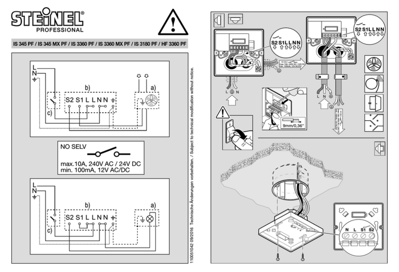
STEINEL PROFESSIONAL
STEINEL PROFESSIONAL IS 345 MX PF manual
