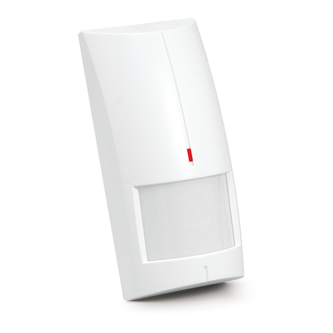
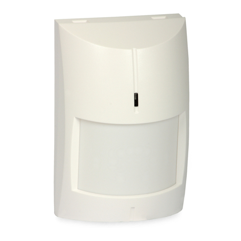
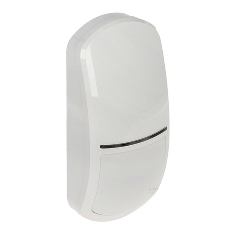
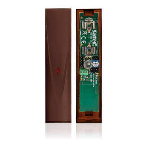
Satel APMD-250 User manual

APMD-250
Wireless dual technology motion detector
Firmware version 1.00 apmd-250_en 01/19
SATEL sp. z o.o. • ul. Budowlanych 66 • 80-298 Gdańsk • POLAND
tel. +48 58 320 94 00
www.satel.eu

IMPORTANT
The device should be installed by qualified personnel.
Prior to installation, please read carefully this manual.
Changes, modifications or repairs not authorized by the manufacturer shall void your rights
under the warranty.
The rating plate of the device is located on the enclosure base.
SATEL aims to continually improve the quality of its products, which may result in changes in
their technical specifications and software. Current information about the changes being
introduced is available on our website.
Please visit us at:
http://www.satel.eu
Hereby, SATEL sp. z o.o. declares that the radio equipment type APMD-250 is in
compliance with Directive 2014/53/EU. The full text of the EU declaration of conformity
is available at the following internet address: www.satel.eu/ce
The following symbols may be used in this manual:
- note,
- caution.

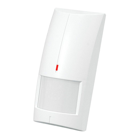
The APMD-250 detector can detect motion in a protected area. It is designed for operation
within the ABAX 2 / ABAX two-way wireless system. This manual applies to the detector with
firmware version 1.00 (or newer), which is supported by:
ABAX 2:
– ACU-220 / ACU-280 controller,
– ARU-200 repeater.
ABAX:
– ACU-120 / ACU-270 controller (firmware version 5.04 or newer),
– ARU-100 repeater (firmware version 2.02 or newer),
– INTEGRA 128-WRL control panel (firmware version 1.19 or newer and firmware
version of processor used to operate ABAX system 3.10 or newer).
1 Features
Passive infrared (PIR) sensor and microwave sensor.
Adjustable detection sensitivity of both sensors.
Digital motion detection algorithm for both sensors.
Digital temperature compensation.
Capability of separate sensor testing.
Option to enable / disable the creep zone protection.
Ability to replace the lens with a curtain or long-range one.
Encrypted two-way radio communication in the 868 MHz frequency band (AES standard
for the ABAX 2 system).
Transmission channel diversity – 4 channels for automatic selection of the one that will
enable transmission without interference with other signals in the 868 MHz frequency
band (ABAX 2 system only).
Remote update of detector firmware (ABAX 2 system only).
Remote configuration.
Built-in temperature sensor (temperature measurement range from -10°C to +55°C).
LED indicators.
Supervision of motion detection system.
“ECO” option for longer battery life (ABAX 2 system only).
Battery status control.
Tamper protection against enclosure opening and removal from mounting surface.
Adjustable mounting bracket included.
2 Specifications
Operating frequency band ...................................................................868.0 MHz ÷ 868.6 MHz
Radio communication range (in open area)
ABAX 2
ACU-220 .............................................................................................. up to 2000 m
ACU-280 .............................................................................................. up to 1600 m
ABAX.............................................................................................................. up to 500 m
Battery ................................................................................................................... CR123A 3 V

2 APMD-250 SATEL
Battery life expectancy .......................................................................................... up to 2 years
Temperature measurement range .......................................................................-10°C...+55°C
Temperature measurement accuracy ................................................................................±1°C
Standby current consumption .......................................................................................... 75 µA
Maximum current consumption ........................................................................................13 mA
Microwave frequency ..............................................................................................24.125 GHz
Detectable speed ...................................................................................................... 0.3...3 m/s
Warm-up period ..................................................................................................................40 s
Recommended installation height ............................................................................ 2 m...2.4 m
Coverage area ................................................................................................15 m x 24 m, 90°
Complied with standards..................................................EN50131-1, EN50130-4, EN50130-5
Security grade according to EN50131-2-4 (detector mounted directly to the wall)........ Grade 2
Environmental class according to EN50130-5 .........................................................................II
Operating temperature range...............................................................................-10°C...+55°C
Maximum humidity ..........................................................................................................93±3%
Dimensions ................................................................................................... 62 x 137 x 42 mm
Weight...............................................................................................................................152 g
3 Description
Radio communication
The detector connects to the controller / control panel at regular time intervals to provide
information about its state (periodical communication). Additional communication may take
place as a result of alarm (see “Operating modes”).
Alarms
The detector will report alarm:
after detecting a motion in the protected area by both sensors within a time period shorter
than 5 seconds (this alarm can only be reported in the active mode – see “Operating
modes”),
after detecting a fault in the motion detection system,
after opening the tamper switch (tamper alarm).
Operating modes
Active – information about tamper alarm and motion detection alarm is sent immediately.
The microwave sensor is enabled after motion is detected by the infrared sensor.
Passive – only information about tamper alarm is sent immediately. The microwave sensor is
disabled, therefore no alarm can be triggered after motion is detected. During periodical
communication, information on whether the PIR sensor detects motion is sent. This
operating mode prolongs the battery life.
The detector operating mode is turned on remotely. If the detector is used in the INTEGRA /
VERSA alarm system, the operating mode may depend on the partition state (partition
disarmed – passive mode; partition armed – active mode). For more information, refer to the
ABAX 2 / ABAX controller manual / the INTEGRA 128-WRL control panel manual.
Energy saving mode (ECO)
If you want to prolong the battery life, you can enable in the detector the “ECO” option. When
the “ECO” option is enabled, the periodical communication takes place every 3 minutes. Thus
SATEL APMD-250 3
the battery life can be increased as much as fourfold. The option is only available in the
ABAX 2 system. The detector with “ECO” option enabled meets requirements of the
EN50131-2-4 standard for Grade 2.
Test mode
The test mode makes the detector testing easier, because the LED indicators are enabled.
How to start and end the test mode is described in the ABAX 2 / ABAX controller manual /
the INTEGRA 128-WRL control panel manual.
LEDs
The LEDs are flashing for about 40 seconds from inserting the battery, thus signaling the
warm-up of the detector. The LEDs also work in the test mode, in which they indicates:
periodical communication – short flash (80 milliseconds),
motion detection – ON for 2 seconds.
Supervision of motion detection system
When the motion detection system starts malfunctioning, the detector will report an alarm
during periodical communication. The alarm will keep going until the fault is cleared (long
violation).
Battery status control
When the battery voltage is below 2.75 V, information about low battery is sent during each
transmission.
In response to the battery voltage drop below 2.75 V, sensitivity of sensors in the
detector is automatically lowered to eliminate false alarms.
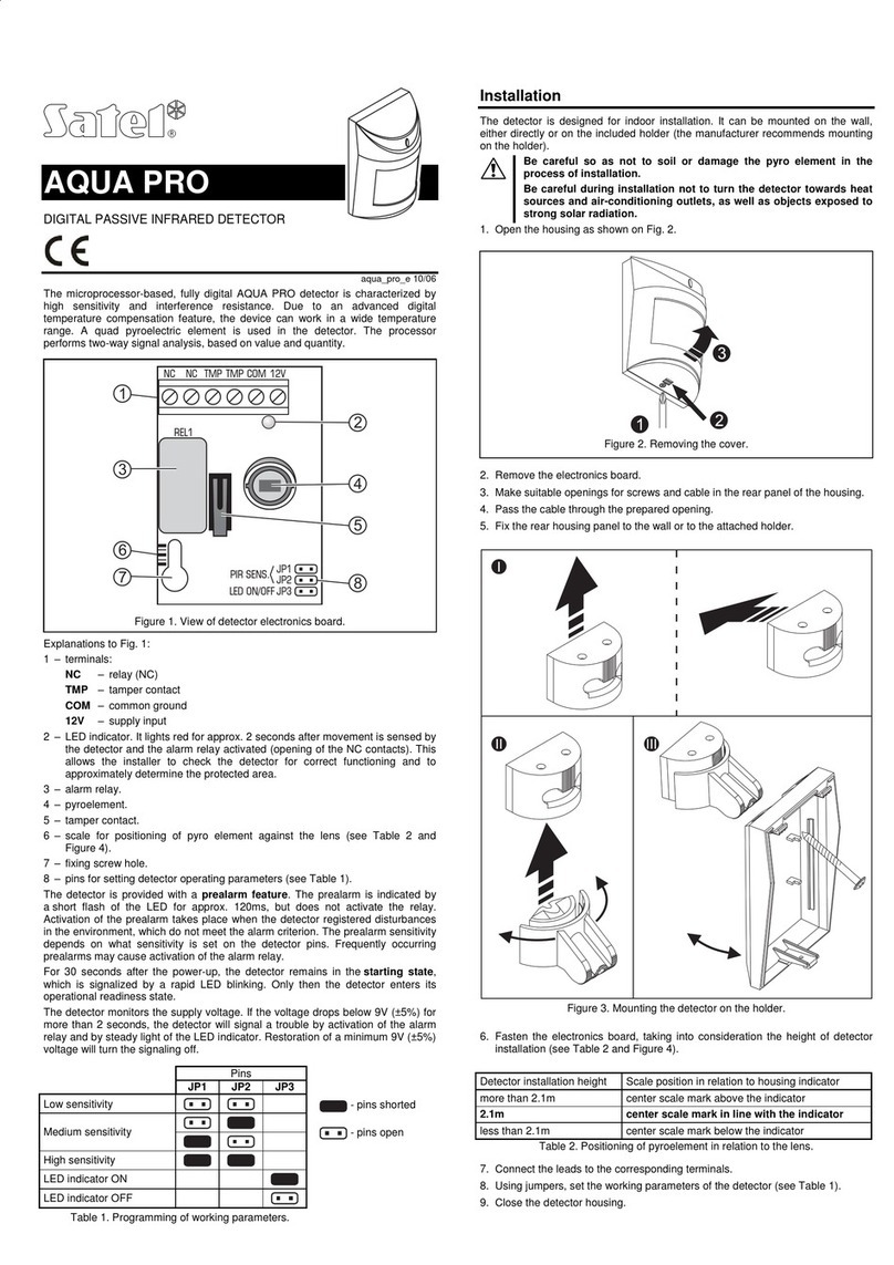
Electronics module
Do not remove the plastic cover from
the circuit board to prevent damage to
the components located on the board.
Do not touch the pyroelectric sensor,
so as not to soil it.
CR123A lithium battery.
microwave sensor.
LED indicator.
element not used.
tamper switch activated by cover removal.
PIR sensor (dual element pyrosensor).
On the other side of the electronics module is
a tamper switch activated by removing the
detector from the wall.

4 APMD-250 SATEL
4 Installation
There is a danger of battery explosion when using a different battery than
recommended by the manufacturer, or handling the battery improperly.
Be particularly careful during installation and replacement of the battery. The
manufacturer is not liable for the consequences of incorrect installation of the
battery.
The used batteries must not be discarded, but should be disposed of in
accordance with the existing rules for environment protection.
1. Remove the front cover (Fig. 2).
2. Move the electronics module down to unlock it, and then remove it from the enclosure
base (Fig. 3).
3. Install the battery and add the detector to the wireless system (see the ABAX 2 / ABAX
controller manual or the INTEGRA 128-WRL control panel installer manual). The sticker
with serial number which shall be entered when registering the detector in the system can
be found on the electronics module.
In the INTEGRA / VERSA alarm system, the detector is identified as APMD-150.
Simultaneous operation of the detector by the ABAX 2 and ABAX controller /
INTEGRA 128-WRL alarm control panel is not possible.
4. Place the electronics module in the enclosure base and then move it up to lock it.
5. Replace the cover.

SATEL APMD-250 5
6. Put the detector at the place of its future installation.
7. Check the level of signal received from the detector by the ABAX 2 / ABAX controller or
the INTEGRA 128-WRL control panel. If the signal level is lower than 40%, select another
place for installation. Sometimes, it is sufficient to shift the device ten or twenty
centimeters to obtain a considerable improvement in the signal quality.
The ARF-200 tester makes it possible to check the radio signal strength at the place of
future installation without having to put the detector there.
8. Remove the front cover (Fig. 2) and remove the electronics module (Fig. 3).
9. Make screw holes in the enclosure base.
10.Secure the enclosure base to the wall (Fig. 4) or the bracket fastened with screws to the
wall or ceiling (Fig. 5). The wall plugs (anchors) delivered with the device are intended for
concrete, brick, etc. For other types of surface (drywall, styrofoam), use the appropriately
selected wall plugs.
If the detector is to comply with the EN50131-2-4 requirements for Grade 2, do not
install it on the mounting bracket (if installed on the bracket, the detector will comply
with the standard requirements for Grade 1).
11.Fasten the electronics module in the enclosure.
12.If the detector is to protect the creep zone, the knob located on the inner side of the
enclosure cover is to be set in position shown in Fig. 6-A. If the detector is NOT to protect
the creep zone, set the knob to the position shown in Fig. 6-B.

6 APMD-250 SATEL
13.Replace the cover.
14.Configure the detector settings (sensitivity of PIR sensor, sensitivity of microwave sensor,
the way of operation in test mode, etc. – see the ABAX 2 / ABAX controller manual / the
INTEGRA 128-WRL control panel manual).
15.Start the test mode (see the ABAX 2 / ABAX controller manual / the INTEGRA 128-WRL
control panel manual).
16.Check whether moving around within the detector coverage area will get the LEDs to
come on. Fig. 7 shows the maximum detection range and the creep zone of
a detector placed at a height of 2.4 m.
Fig. 7 shows the range of APMD-250 detector with the wide-angle (WD) Fresnel lens,
which is installed in the detector as standard one. You can change the detector
enclosure cover to install another lens instead. The SATEL product range includes
covers with the curtain (CT) lens as well as with the long-range (LR) lens.
17.End the test mode.

SATEL APMD-250 7

8 APMD-250 SATEL
This manual suits for next models
2
Table of contents
Other Satel Security Sensor manuals

Satel
Satel AMD-102 User manual

Satel
Satel AQUA RING S User manual

Satel
Satel AQUA PRO User manual

Satel
Satel ASD-110 User manual

Satel
Satel VD-1 User manual

Satel
Satel SILVER User manual

Satel
Satel OPAL Pro User manual

Satel
Satel AQUA RING S User manual

Satel
Satel ABAX 2 APD-200 User manual

Satel
Satel AGD-200-BR User manual
Popular Security Sensor manuals by other brands

Abra
Abra AK-325 quick start guide

Honeywell
Honeywell TRADELINE C554A installation instructions

PCB Piezotronics
PCB Piezotronics 482C24-SU Installation and operating manual

Antec Scientific
Antec Scientific FlexCell user manual

ipf electronic
ipf electronic UT990895 manual

ELRO
ELRO FC451011 instruction manual