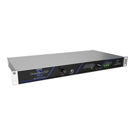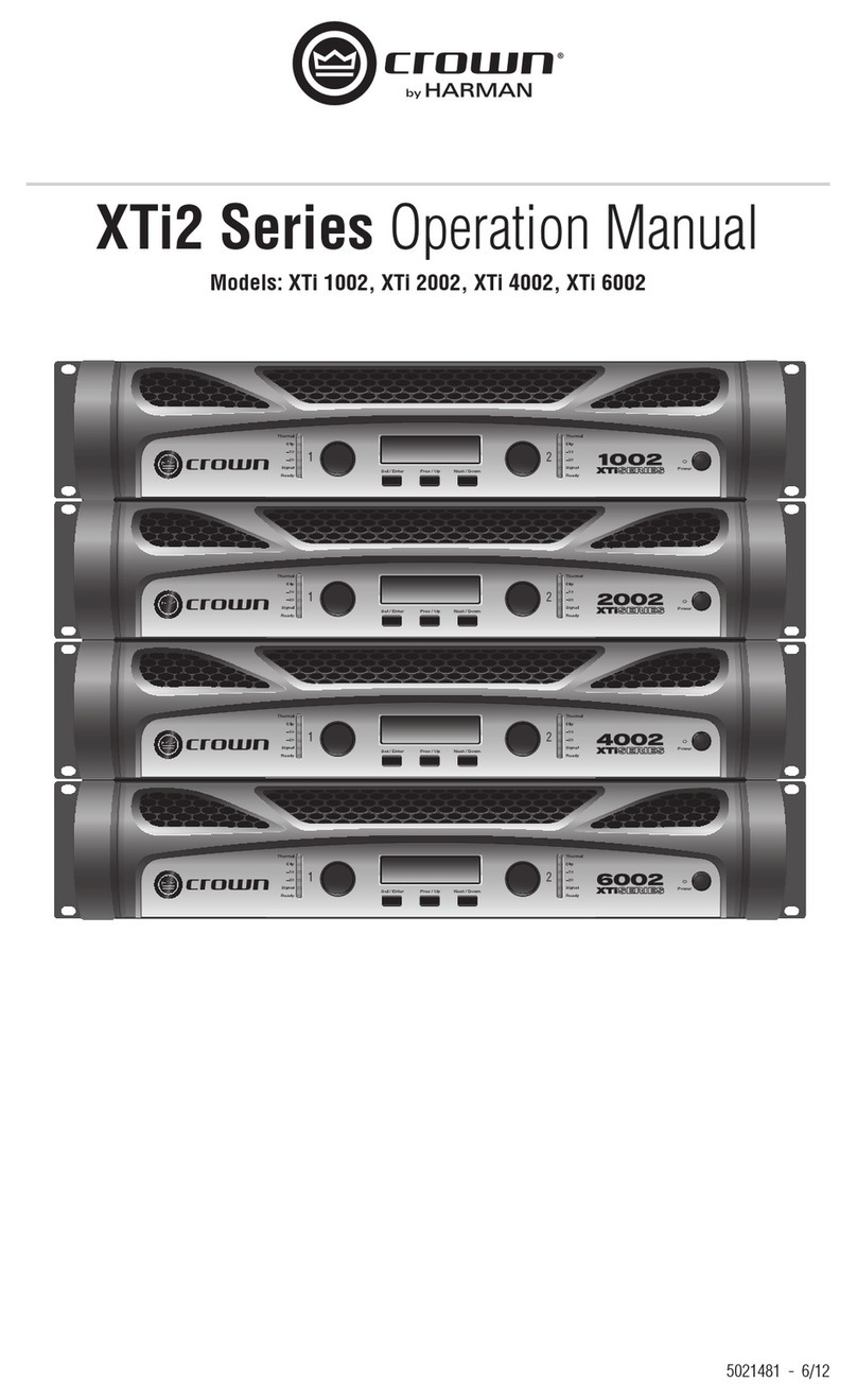
AXYS®IndustryAmp User Manual rev 2.2
201605/IAMP_2.2
4
This symbol is intended to alert you to the
presence of uninsulated dangerous voltages
within the product’s enclosure that may be of sufficient
magnitude to constitute a risk of electric shock.
This symbol is used throughout this manual and
is intended to alert you to the presence of
important instructions.
1. Read these instructions.
2. Keep these instructions.
3. Heed all warnings.
4. Follow all instructions.
5. Do not use this apparatus near water.
6. Clean only with dry cloth.
7. Do not block any ventilation openings. Install in
accordance with the manufacturer’s instructions.
8. Do not install near any heat sources such as radiators,
heat registers, stoves, or other apparatus (including
amplifiers) that produce heat.
9. Do not defeat the safety purpose of the polarised or
grounding-type plug. A grounding type plug has two
blades and a third grounding prong. The wide blade
or the third prong is provided for your safety. If the
provided plug does not fit into your outlet, consult
an electrician for replacement of the obsolete outlet.
10. Protect the power cord from being walked on or
pinched particularly at plugs, convenience receptacles,
and the point where they exit from the apparatus.
11. Only use attachments/accessories specified by the
manufacturer.
12. Unplug this apparatus during lightning storms or
when unused for long periods of time.
13. Refer servicing to qualified service personnel.
Servicing is required when the apparatus has been
damaged in any way, such as power-supply cord or
plug is damaged, liquid has been spilled or objects
have fallen into the apparatus, the apparatus has
been exposed to rain or moisture, does not operate
normally, or has been dropped.
Warning - To reduce the risk of fire or electric
shock, do not expose this apparatus to rain or
moisture and objects filled with liquids, such as vases,
should not be placed on this apparatus.
Warning - To disconnect this apparatus from the
mains power supply, turn off the power at the
power switch on the rear panel and remove the PowerCon®
connector from the mains input socket labelled Mains on
the rear panel.
Warning - The PowerCon®connector should
never be plugged or unplugged when there is
power on the connector, regardless of whether the
amplifier is switched on or not. ALWAYS ensure that the
mains supply is turned off at source before inserting or
removing the PowerCon®.
Warning - This apparatus is a Class I device and
must be connected to a mains socket outlet that
provides a safety ground connection.
IMPORTANT SAFETY INSTRUCTIONS
