manuals.online logo
Brands
  1. Home
  2. •
  3. Brands
  4. •
  5. Harman
  6. •
  7. Amplifier
  8. •
  9. Harman JBL Stage A6002 User manual

Harman JBL Stage A6002 User manual

STAGE A6002
SKU: STAGEA6002
01/2019
Ver. 1.0
Safety Instruction, Warning & Notes
Specifications
Set Block Diagram
Schematic Diagrams
Layout Diagrams
Set Mechanical Exploded View
Packaging View
Spare Parts List
Revision List
CONTCONTENTSENTS
2
5
8
9
12
14
15
16
17
1. Read these instructions.
2. Keep these instructions.
3. Heed all warnings.
4. Follow all instructions.
5. Do not use this apparatus near water.
6. Clean only with a dry cloth.
7. Do not block any ventilation openings.Install in accordance with the manufacturer’s instructions.
8. Do not install near any heat sources such as radiators, heat registers, stoves or other apparatus (including
amplifiers) that produce heat.
9. Do not defeat the safety purpose of the polarized or grounding-type plug. A polarized plug has two blades with one
wider than the other. A grounding-type plug has two blades and a third grounding prong. The wide blade or the
third prong is provided for your safety. If the provided plug does not fit into your outlet, consult an electrician for
replacement of the obsolete outlet.
10. Protect the power cord from being walked on or pinched, particularly at plugs, convenience receptacles and the
point where they exit from the apparatus.
11. Only use attachments/accessories specified by the manufacturer.
12. Use only with the cart, stand, tripod, bracket or table specified by the manufacturer or sold with the
apparatus. When a cart is used, use caution when moving the cart/apparatus combination to avoid
injury from tip-over.
13. Unplug this apparatus during lightning storms or when unused for long periods of time.
14. Refer all servicing to qualified service personnel. Servicing is required when the apparatus has been damaged
in any way, such as power supply cord or plug is damaged, liquid has been spilled or objects have fallen into the
apparatus, or the apparatus has been exposed to rain or moisture, does not operate normally or has been dropped.
15. Do not expose this apparatus to dripping or splashing and ensure that no objects filled with liquids, such as vases,
are placed on the apparatus.
16. To completely disconnect this apparatus from the AC Mains, disconnect the power supply cord plug from the AC
receptacle.
17. The mains plug of the power supply cord shall remain readily operable.
18. Do not expose batteries to excessive heat such as sunshine, fire or the like.
For Products That Transmit and
Receive RF Energy:
FCC Regulations (USA Only)
FCC Information For Users
This device complies with Part 15 of the FCC Rules. Operation
is subject to the following two conditions: (1) This device
may not cause harmful interference; and (2) this device must
accept any interference received, including interference that
may cause undesired operation.
Radio and Television Interference
This equipment has been tested and found to comply with
the limits for a Class B digital device, pursuant to Part 15
of the FCC Rules. These limits are designed to provide
reasonable protection against harmful interference in a
residential installation. This equipment generates, uses and
can radiate radio frequency energy and, if not installed and
used in accordance with the instructions, may cause harmful
interference to radio communications. However, there is no
guarantee that interference will not occur in a particular
installation. If this equipment does cause interference to radio
or television reception, which can be determined by turning
the equipment off and then on, the user is encouraged to try
to correct the interference by one or more of the following
measures:
•Increase the separation between the equipment and
receiver.
•Connect the equipment to a different outlet so that the
equipment and receiver are on different branch circuits.
•Consult the dealer or an experienced radio/TV technician
for help.
NOTE: Changes or modifications not expressly approved
by Harman could void the user’s authority to operate the
equipment.
IC Statement and Warning (Canada Only)
This Class B digital apparatus complies with Canadian ICES-
003. Cet appareil numérique de la classe B est conforme à la
norme NMB-003 du Canada.
For Canadian Model
This Class B digital apparatus complies with Canadian
ICES-003.
Modèle pour les Canadien
Cet appareil numérique de la classe B est conforme à la
norme NMB-003 du Canada.
For Products with Radio Receivers
That Can Use an External Antenna:
CATV or Antenna Grounding
If an outside antenna or cable system is connected to this
product, be certain that it is grounded so as to provide some
protection against voltage surges and static charges. Section
810 of the National Electrical Code, ANSI/NFPA No. 70-1984,
provides information with respect to proper grounding of the
mast and supporting structure, grounding of the lead-in wire
to an antenna discharge unit, size of grounding conductors,
location of antenna discharge unit, connection to grounding
electrodes and requirements of the grounding electrode.
Note to CATV System Installer:
This reminder is provided to call the CATV (cable TV) system
installer’s attention to article 820-40 of the NEC, which
provides guidelines for proper grounding and, in particular,
specifies that the cable ground shall be connected to the
grounding system of the building, as close to the point of
cable entry as possible.
For CD/DVD/Blu-ray Disc™Players:
Caution:
This product uses a laser system. To prevent direct exposure
to the laser beam, do not open the cabinet enclosure or defeat
any of the safety mechanisms provided for your protection.
DO NOT STARE INTO THE LASER BEAM. To ensure proper use
of this product, please read the owner’s manual carefully and
retain it for future use. Should the unit require maintenance
or repair, please contact your local Harman Kardon service
center. Refer servicing to qualified personnel only.
For Products That Include Batteries:
Instructions for Users on Removal and Disposal of
Used Batteries.
CAUTION
Risk of explosion if battery is incorrectly replaced.
Replace only with the same or equivalent type.
Alkaline batteries are considered nonhazardous.
Rechargeable batteries (i.e., nickel cadmium, nickel metal-
hydride, lithium and lithium-ion) are considered hazardous
household materials and may pose an unnecessary health
and safety risk.
In the European Union and other locations, it is illegal to
dispose of any battery with household trash. All batteries
must be disposed of in an environmentally sound manner.
Contact your local waste management officials for information
regarding the environmentally sound collection, recycling and
disposal of used batteries.
To remove the batteries from your equipment or remote
control, reverse the procedure described for inserting
batteries in the owner’s manual.
For products with a built-in battery that lasts for the lifetime of
the product, removal may not be possible for the user. In this
case, recycling or recovery centers handle the dismantling of
the product and the removal of the battery. If, for any reason, it
becomes necessary to replace such a battery, this procedure
must be performed by authorized service centers.
Important Safety Instructions
CAUTION
RISK OF ELECTRIC SHOCK. DO NOT OPEN.
THE LIGHTNING FLASH WITH AN ARROWHEAD SYMBOL,
WITHIN AN EQUILATERAL TRIANGLE, IS INTENDED TO
ALERT THE USER TO THE PRESENCE OF UNINSULATED
“DANGEROUS VOLTAGE” WITHIN THE PRODUCT’S
ENCLOSURE THAT MAY BE OF SUFFICIENT MAGNITUDE TO
CONSTITUTE A RISK OF ELECTRIC SHOCK TO PERSONS.
THE EXCLAMATION POINT WITHIN AN EQUILATERAL
TRIANGLE IS INTENDED TO ALERT THE USER TO
THE PRESENCE OF IMPORTANT OPERATING AND
MAINTENANCE (SERVICING) INSTRUCTIONS IN THE
LITERATURE ACCOMPANYING THE PRODUCT.
WARNING: TO REDUCE THE RISK OF FIRE OR ELECTRIC
SHOCK, DO NOT EXPOSE THIS APPARATUS TO RAIN OR
MOISTURE.
BDS 270 / BDS 570 harman/kardon
2 of 86

Each precaution in this manual should be followed during servicing.
Components identified with the IEC symbol in the parts list are special significance to safety. When replacing a component identified with
, use only the replacement parts designated, or parts with the same ratings or resistance, wattage, or voltage that are designated in the
parts list in this manual. Leakage-current or resistance measurements must be made to determine that exposed parts are acceptably
insulated from the supply circuit before retuming the product to the customer.
Some semiconductor (solid state) devices can be damaged easily by static electricity. Such components commonly are called
Electrostatically Sensitive (ES) Devices. Examples of typical ES devices are integrated circuits and some field effect transistors and
semiconductor "chip" components.
The following techniques should be used to help reduce the incidence of component damage caused by static electricity.
1. Immediately before handling any semiconductor component or semiconductor-equipped assembly, drain off any electrostatic charge on
your body by touching a known earth ground. Alternatively, obtain and wear a commercially available discharging wrist strap device,
which should be removed for potential shock reasons prior to applying power to the unit under test.
2. After removing an electrical assembly equipped with ES devices, place the assembly on a conductive surface such as aluminum foil, to
prevent electrostatic charge build-up or exposure of the assembly.
3. Use only a grounded-tip soldering iron to solder or unsolder ES devices.
4. Use only an anti-static solder removal device. Some solder removal devices not classified as "anti-static" can generate electrical charges
sufficient to damage ES devices.
5. Do not use freon-propelled chemicals. These can generate electrical change sufficient to damage ES devices.
6. Do not remove a replacement ES device from its protective package until immediately before you are ready to install it. (Most replacement
ES devices are packaged with leads electrically shorted together by conductive foam, aluminum foil or comparable conductive material.)
7. Immediately before removing the protective material from the leads of a replacement ES device, touch the protective material to the
chassis or circuit assembly into which the device will be installed.
Be sure no power is applied to the chassis or circuit, and observe all other safety precautions.
8. Minimize bodily motions when handling unpackaged replacement ES devices. (Otherwise harmless motion such as the brushing together
or your clothes fabric or the lifting of your foot from a carpeted floor can generate static electricity sufficient to damage an ES devices.
CAUTION :

SAFETY PRECAUTIONS
The following check should be performed for the continued
protection of the customer and service technician.
LEAKAGE CURRENT CHECK
Measure leakage current to a known earth ground (water
pipe, conduit, etc.) by connecting a leakage current tester
between the earth ground and all exposed metal parts of the
appliance (input/output terminals, screwheads, metal
overlays, control shaft, etc.). Plug the AC line cord of the
appliance directly into a 120V AC 60Hz outlet and turn the
AC power switch on. Any current measured must not exceed
o.5mA.
ANY MEASUREMENTS NOT WITHIN THE LIMITS
OUTLINED ABOVE ARE INDICATIVE OF A
POTENTIAL SHOCK HAZARD AND MUST BE
CORRECTED BEFORE RETURNING THE APPLIANCE
TO THE CUSTOMER.
Device
under
test
Test all
exposed metal
surfaces
Also test with
plug reversed
(Using AC adapter
plug as required)
AC Leakage Test
Leakage
current
tester
Reading should
not be above
0.5mA
Earth
ground

There’s Nothing Better Than Riding With JBL
Stage Amplifiers
Features
Value Engineered
Compact footprint
Full On-Board Protection
Reliability
Input Level Control
Switchable bass EQ
Cool industrial design
Crossover mode switch
Crossover control gives user
additional fine tuning
Our Point of View
Power you will feel at your core.
JBL Stage Amps are available in a variety of configurations, delivering the right power and
number of channels for full-range and subwoofer applications. For more than four decades,
JBL has made the audio experience a lot more satisfying for the car audio enthusiast. With
a broad array of loudspeakers, amplifiers and subwoofers available, you can drive with ease
and exhilaration. These compact amps are equipped with all the important inputs and user
controls including a bass EQ as well as LPF and HPF crossover controls for tailoring sound to
suit the characteristics of different vehicles. The Stage Amps are easily installed and amazingly
reliable – and once they turn on, they’ll make a transducer sit up and sing.
JBL Stage A6002 JBL Stage A6004 JBL Stage A9004 JBL Stage A3001
JBL Stage Amplifier A9004
JBL Stage Amplifier A6004
JBL Stage Amplifier A6002
There’s Nothing Better Than Riding With JBL
Stage Amplifiers
Features and Benefits
Value Engineered
Stage amplifier provides true JBL performance at an affordable price while now lacking the features needed to properly tune and optimize performance.
Compact footprint
With it becoming more and more difficult to find spacious locations for amplifier mounting, Stage has been developed in a small compact form factor
to allow more location versatility.
Full On-Board Protection
Stage amplifier has on-board circuitry to protect them from shorts, temperature, overvoltage and undervoltage. An LED indicator is included on all
four models to let you know when one of these conditions exists.
Reliability
JBL is one of the greatest audio brands in the world. This is not a coincidence given the arduous testing and quality control. We take our craft seriously
and want every consumer to have a world-class experience that lasts and lasts.
Input Level Control
When Low-level inputs are used, this control adjusts the input sensitivity between 200mVrms and 5.0Vrms. When High-level inputs are used,
this control adjusts the input sensitivity between 0.5Vrms and 15Vrms.
Switchable bass EQ
This provides an available bass boost at 45Hz of 6dB or 12dB, serving as a great tool to optimize subwoofer and loudspeaker performance based
on location and enclosure type.
Cool industrial design
Black with deep grooves, silver silkscreen, anodized JBL badge top-center with orange end panels and bottom.
Crossover mode switch*
LPF crossover controls is switchable between 0dB to 12dB at 45Hz giving user ability to adjust sound to the environment and/or application.
Crossover control gives user additional fine tuning*
Adjusts the crossover turnover frequency between 32Hz and 320Hz. (One knob for each stereo pair.)
Our Point of View
JBL believes that life is defined by what you experience. Music helps people have experiences that are more extraordinary, by fully immersing them
in each moment. To help people have rich experiences, JBL creates full-on sound that draws people in and heightens the feeling. JBL is dedicated
to delivering sound that elevates life.
*Not applicable for JBL Stage A3001
JBL Stage Amplifier A3001
HARMAN International Industries, Incorporated
8500 Balboa Boulevard, Northridge, CA 91329 USA
www.jbl.com
©2018 HARMAN International Industries, Incorporated. All rights reserved. JBL is a trademark of HARMAN International
Industries, Incorporated, registered in the United States and/or other countries. Features, specifications and appearance
are subject to change without notice.
There’s Nothing Better Than Riding With JBL
Stage Amplifiers
What’s in the Box
Amplifier
Spare Fuse (x2 for 1-channel and 4-channel model)
Quick start guide
High-level input cable (x2 for 4-channel model)
2x two-color JBL Brand Stickers
Mounting hardware
Mounting screws
Technical Specifications:
Stage A6002
Operating voltage 9 – 16V
RMS power @ 4 ohms 60W
RMS power @ 2 ohms 70W
RMS bridged power @ 4 ohms 140W
Total peak power 280W
Frequency response 20Hz – 20kHz @ -1dB
THD + N at rated power
(20Hz – 20kHz) <1%
Line-in signal-to-noise ratio
(reference to 1 watt) >75dB
Maximum high input signal level 12V
High input maximum sensitivity 0.5V
Maximum line input signal level 5V
Line input maximum sensitivity 0.2V
Quiescent current draw <1.0A
Fuse size 20A
Dimensions (H x W x L) 50 x 145 x 156.6mm
Weight 1.16kg
Stage A6004
Operating voltage 9 – 16V
RMS power @ 4 ohms 60W
RMS power @ 2 ohms 70W
RMS bridged power @ 4 ohms 140W
Total peak power 560W
Frequency response 20Hz – 20kHz @ -1dB
THD + N at rated power
(20Hz – 20kHz) <1%
Line-in signal-to-noise ratio
(reference to 1 watt) >75dB
Maximum high input signal level 12V
High input maximum sensitivity 0.5V
Maximum line input signal level 5V
Line input maximum sensitivity 0.2V
Quiescent current draw <1.2A
Fuse size 2 x 15A
Dimensions (H x W x L) 50 x 145 x 193.6mm
Weight 1.381kg
Stage A9004
Operating voltage 9 – 16V
RMS power @ 4 ohms 90W
RMS power @ 2 ohms 110W
RMS bridged power @ 4 ohms 220W
Total peak power 880W
Frequency response 20Hz – 20kHz @ -1dB
THD + N at rated power
(20Hz – 20kHz) <1%
Line-in signal-to-noise ratio
(reference to 1 watt) >75dB
Maximum high input signal level 12V
High input maximum sensitivity 0.5V
Maximum line input signal level 5V
Line input maximum sensitivity 0.2V
Quiescent current draw <1.5A
Fuse size 2 x 20A
Dimensions (H x W x L) 50 x 145 x 268.6mm
Weight 1.806kg
Stage A3001
Operating voltage 9 – 16V
RMS power @ 4 ohms N/A
RMS power @ 2 ohms 300W
RMS bridged power @ 4 ohms N/A
Total peak power 600W
Frequency response 10Hz – 320kHz @ -3dB
THD + N at rated power
(20Hz – 20kHz) <1%
Line-in signal-to-noise ratio
(reference to 1 watt) >75dB
Maximum high input signal level 12V
High input maximum sensitivity 0.5V
Maximum line input signal level 5V
Line input maximum sensitivity 0.2V
Quiescent current draw <1.5A
Fuse size 2 x 15A
Dimensions (H x W x L) 50 x 145 x 241.6mm
Weight 1.609kg
SET BLOCK DIAGRAM
YTQnoitpircseDN/P.oN.soP
1A2006/2006ADRAOBNIAMN-0-0012-845020-6001
11 9006095002006 INSULATION TAPE W/O GLUE A6002/6002A 1
12 20M0070000002 DEPRESSION BAR 38MM A6002/6002A 1
13 20M0070000001 DEPRESSION BAR 28MM A6002/6002A 1
15 20M0070000003 DEPRESSION BAR 21MM A6002/6002A 1
17 9006095002004 INSULATION TAPE W/GLUE A6002/6002A 1
PACKAGING INSTRUCTIONS
Spare Parts List v1.0
Pos. No. Product Name P/N Description Usage
10 Stage-A6002 Primus-6002a 06-020548-2100-0-N MAIN BOARD A6002/6002A 1
11 Stage A6002, Primus 6002a 9006095002006 INSULATION TAPE W/O GLUE A6002/6002A 1
12 Stage A6002, Primus 6002a 20M0070000002 DEPRESSION BAR 38MM A6002/6002A 1
13 Stage A6002, Primus 6002a 20M0070000001 DEPRESSION BAR 28MM A6002/6002A 1
15 Stage A6002, Primus 6002a 20M0070000003 DEPRESSION BAR 21MM A6002/6002A 1
17 Stage A6002, Primus 6002a 9006095002004 INSULATION TAPE W/GLUE A6002/6002A 1
C1 C2 Stage A6002, Primus 6002a 10C5332740001 CAP. 3300U/25V 土20% 105ԨA6002/6002A 2
C17 C18 Stage A6002, Primus 6002a 10C6222750001 CAP. 2200UF/35V ±20% A6002/6002A/A9004/9004A 2
CON2 Stage A6002, Primus 6002a 10J500004P001 CONNECTOR 4P JSZ4-03 A6002/6002A 1
CON3 Stage A6002, Primus 6002a 10J500003P001 CONNECTOR 3P JSZ3-03 A6002/6002A/A9004/9004A 1
D16 Stage A6002, Primus 6002a 10D71620CT001
HALF
-
BRIDGE
MUR1620CTR
A6002/6002AA9004/9004A
1
D17 Stage A6002, Primus 6002a 10D71620CT002 HALF-BRIDGE MUR1620CT A6002/6002AA9004/9004A 1
J1 Stage A6002, Primus 6002a 10J528413A001 CONNECTOR RCA A6002/6002A 1
L7 Stage A6002, Primus 6002a 10L0270000001 TRANSFORMER D27*12-16 A6002/6002A 1
LED1 Stage A6002, Primus 6002a 10D4260030001 LED D3 RED/BLU 3P A6002/6002A/A9004/9004A 1
Q11 Q12 Stage A6002, Primus 6002a 10T0RF3205001 MOS TUBE IRF3205 A6002/6002A/A9004/9004A 2
SW1 Stage A6002, Primus 6002a 10K0010000002 SWITCH 2P3T L8MM A6002/6002A/A9004/9004A 1
TR1 Stage A6002, Primus 6002a 10R4501000002 NTC THERMISTOR 10K A6002/6002A/A9004/9004A 1
U1 Stage A6002, Primus 6002a 10I0DA8920001 IC TDA8920CTH AMP A6002/6002A 1
U2 Stage A6002, Primus 6002a 10I0078L05001 REGULATOR 78L05 A6002/6002A/A9004/9004A 1
U3 Stage A6002, Primus 6002a 10I0J78L12001 IC CJ78L12 A6002/6002A/A9004/9004A 1
U4 Stage A6002, Primus 6002a 10I0J79L12001 IC CJ79L12 A6002/6002A/A9004/9004A 1
U5 Stage A6002, Primus 6002a 10I00TL494001 IC TL494CD A6002/6002A/A9004/9004A 1
U6 U7 U9 Stage A6002, Primus 6002a 10I0L084CN001 IC TL084CN A6002/6002A/A9004/9004A 3
U8 Stage A6002, Primus 6002a 10I0L082CN001 IC TL082CN A6002/6002A/A9004/9004A 1
VR1 Stage A6002, Primus 6002a 10R6200000001 POTENTIOMETER B20K A6002/6002A/A9004/9004A 1
VR3 VR2 Stage A6002, Primus 6002a 10R6100000001 POTENTIOMETER C100K A6002/6002A/A9004/9004A 2
VR4 Stage A6002, Primus 6002a 10R6500000001 POTENTIOMETER B500K A6002/6002A/A9004/9004A 1
Stage A6002, Primus 6002a 10F2200000001 FUSE 20A A9004/9004A/A6002/6002A 1
Stage A6002 50B30A6002001 GIFT BOX A6002 1
Primus 6002a 50B306002a001 GIFT BOX 6002A 1
Stage-A6002 Primus-6002a 40S8000300009 5P HIGH INPUT CABLE A6002/6002A 1
Stage 20M0070157001 JBL LOGO STAGE AMP 1
Primus 20M0070158002 INFINITY LOGO PRIMUS AMP 1
Revision List
Version 1.0
* Initial release for JBL Stage A6002. 2019-1

Other manuals for JBL Stage A6002

1

This manual suits for next models

4

Other Harman Amplifier manuals

Harman JBL SW8A-S User manual

Harman

Harman JBL SW8A-S User manual

Harman JBL DA850 User manual

Harman

Harman JBL DA850 User manual

Harman harman/kardon CITATION AMP User manual

Harman

Harman harman/kardon CITATION AMP User manual

Harman JBL GTO-751EZ User manual

Harman

Harman JBL GTO-751EZ User manual

Harman crown CDi DriveCore Series User manual

Harman

Harman crown CDi DriveCore Series User manual

Harman Crown CTs Series User manual

Harman

Harman Crown CTs Series User manual

Harman JBL BassPro User manual

Harman

Harman JBL BassPro User manual

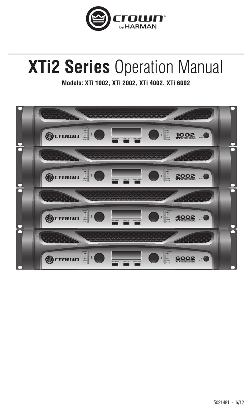
Harman crown XTi Series User manual

Harman

Harman crown XTi Series User manual

Harman JBL Club A754 User manual

Harman

Harman JBL Club A754 User manual

Harman JBL GTO-1001EZ User manual

Harman

Harman JBL GTO-1001EZ User manual

Harman JBL CSMA 180 User manual

Harman

Harman JBL CSMA 180 User manual

Harman JBL PRO POWER A302GTi User manual

Harman

Harman JBL PRO POWER A302GTi User manual

Harman JBL CSA-2120 User manual

Harman

Harman JBL CSA-2120 User manual

Harman JBL Performance Series User manual

Harman

Harman JBL Performance Series User manual

Harman DBX 500 Series User manual

Harman

Harman DBX 500 Series User manual

Harman JBL Commercial VMA Series User manual

Harman

Harman JBL Commercial VMA Series User manual

Harman JBL SUB 550P User manual

Harman

Harman JBL SUB 550P User manual

Harman JBL Stage A6004 User manual

Harman

Harman JBL Stage A6004 User manual

Harman Soundcraft Vi1000 User manual

Harman

Harman Soundcraft Vi1000 User manual

Harman Crown XLi Series User manual

Harman

Harman Crown XLi Series User manual

Harman JBL GTO7520 User manual

Harman

Harman JBL GTO7520 User manual

Harman JBL GTR-104 Assembly instructions

Harman

Harman JBL GTR-104 Assembly instructions

Harman Mark Levinson 585 User manual

Harman

Harman Mark Levinson 585 User manual

Harman JBL Club A600 User manual

Harman

Harman JBL Club A600 User manual

Popular Amplifier manuals by other brands

Margules U280sc 25th user manual

Margules

Margules U280sc 25th user manual

Labgear MSA111 installation instructions

Labgear

Labgear MSA111 installation instructions

Hallicrafters HT-41 Operating and service instructions

Hallicrafters

Hallicrafters HT-41 Operating and service instructions

Pyle Pro PWMA-1003T operating manual

Pyle Pro

Pyle Pro PWMA-1003T operating manual

Kustom Defender V50 owner's manual

Kustom

Kustom Defender V50 owner's manual

CYP CHDMI14 Operation user's manual

CYP

CYP CHDMI14 Operation user's manual

Link electronics AES/EBU DIGITAL AUDIO DA LEI-540 Specification sheet

Link electronics

Link electronics AES/EBU DIGITAL AUDIO DA LEI-540 Specification sheet

Linea Research 44 Series user guide

Linea Research

Linea Research 44 Series user guide

Rotel RA-960BX owner's manual

Rotel

Rotel RA-960BX owner's manual

Maggiore Hi Pro PAV1 Operating and maintenance manual

Maggiore

Maggiore Hi Pro PAV1 Operating and maintenance manual

Takstar E129 quick start guide

Takstar

Takstar E129 quick start guide

MC2 Audio E4-75 owner's manual

MC2 Audio

MC2 Audio E4-75 owner's manual

ARC Audio XDi 850.5 owner's manual

ARC Audio

ARC Audio XDi 850.5 owner's manual

Rotel Dolby Pro Logic Surround Pream owner's manual

Rotel

Rotel Dolby Pro Logic Surround Pream owner's manual

Onkyo FR-155 Service manual

Onkyo

Onkyo FR-155 Service manual

Boss Audio Systems Chaos CH850M Service manual

Boss Audio Systems

Boss Audio Systems Chaos CH850M Service manual

Millenium HP4 user manual

Millenium

Millenium HP4 user manual

Heritage Audio ELITE Series user manual

Heritage Audio

Heritage Audio ELITE Series user manual

manuals.online logo
manuals.online logoBrands
  • About & Mission
  • Contact us
  • Privacy Policy
  • Terms and Conditions

Copyright 2025 Manuals.Online. All Rights Reserved.