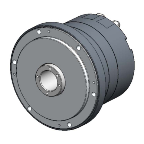
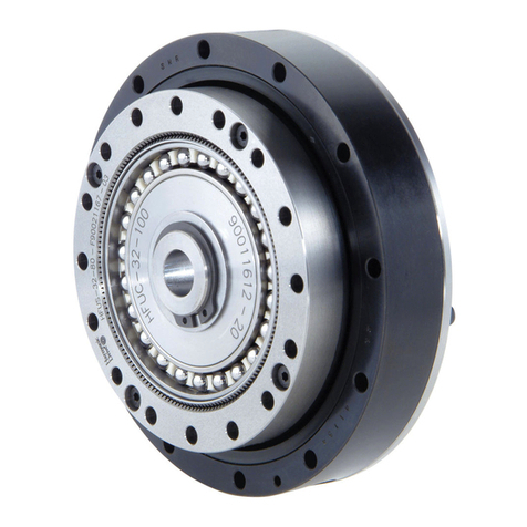
Harmonic Drive KDU Series User manual

Direct Drive Motor
KDU Series Manual
ISO14001
ISO9001

Introduction
Introduction
Thank you very much for purchasing our KDU Series Direct Drive Motor.
Wrong handling or use of this product may result in unexpected accidents or shorter life of the product.
Read this manual carefully and use the product correctly so that the product can be used safely for
many years.
Product specifications are subject to change without notice for improvement purposes.
Keep this manual in a convenient location and refer to it whenever necessary in operating or
maintaining the units.
The end user of the motor should have a copy of this manual.

SAFETY GUIDE
1
SAFETY GUIDE
To use this product safely and correctly, be sure to read the SAFETY GUIDE and other parts of this
document carefully and fully understand the information provided herein before using the driver.
Notation
Important safety information you must note is provided herein. Be sure to observe these instructions.
Indicates a potentially hazardous situation, which, if not avoided, could result
in death or serious personal injury.
Indicates a potentially hazardous situation, which, if not avoided, may result in
minor or moderate personal injury and/or damage to the equipment.
Indicates what should be performed or avoided to prevent non-operation or
malfunction of the product or negative effects on its performance or function.
LIMITATION OF APPLICATIONS
The equipment listed in this document may not be used for the applications listed below:
・Space equipment
・Aircraft, aeronautic equipment
・Nuclear equipment
・Household apparatus
・Vacuum equipment
・Automobile, automotive parts
・Amusement equipment, sport equipment, game machines
・Machine or devices acting directly on the human body
・Instruments or devices to transport or carry people
・Apparatus or devices used in special environments
If the above list includes your intending application for our products, please consult us.
If this product is utilized in any facility in which human life is
at stake or that may incur material losses, install safety
devices so that accidents will not occur even when the
output control is disabled due to damage.
WARNING
CAUTION
CAUTION

SAFETY GUIDE
2
SAFETY NOTE
ITEMS YOU SHOULD NOTE WHEN USING THE MOTOR
NOTICES ON DESIGN
Always use them under the followings conditions:
The motor is designed to be used indoors. Observe the following conditions:
・Ambient temperature: 10 to 30℃
・Ambient humidity: 20 to 80%RH (No condensation)
・Under the environment with no vibration or physical shock
・No contamination by water, oil
・No corrosive or explosive gas
Follow exactly the instructions in the relating manuals to
install the motor in the equipment.
・Ensure exact alignment of the motor shaft center and corresponding center
as per the manual.
・Failure to observe this caution may lead to vibration, resulting in damage of
output shafts.
OPERATIONAL PRECAUTIONS
Never connect cables directly to a power supply socket.
・Each motor must be operated with a proper driver.
・Do not directly apply a commercial power supply. Failure to observe this
caution may lead to fire or damage to the motor.
Do not apply impacts and shocks.
・Because the motor is directly connected to the encoder with high accuracy,
do not apply any impact on it.
・Failure to observe this caution could damage the encoder and may cause
uncontrollable operation.
Avoid handling of motor by cables.
・Rough handling of cables may damage connectors, leading to uncontrolled
operation of the motor.
Keep limited torques of the motor.
・Keep limited torques of the motor.
・When installing a load on the output shaft, keep the weight well balanced.
CAUTION

SAFETY GUIDE
3
ITEMS YOU SHOULD NOTE WHEN USING THE DRIVER
NOTICES ON DESIGN
Always use them under followings conditions:
The driver generates heat. Take extra caution for radiation and use it under the
following conditions.
・Mount in a vertical position keeping sufficient distance to other devices to
let heat generated by the driver radiate freely.
・0 to 50℃, 95% RH or below (No condensation)
・No vibration or physical shock
・No corrosive, inflammable or explosive gas
Use sufficient noise suppressing means and safe grounding.
Any noise generated on a signal wire will cause vibration or improper motion.
Be sure to observe the following conditions.
・Keep signal and power leads separated.
・Keep leads as short as possible.
・Ground motor and driver at one single point, minimum ground resistance
class: D (less than 100 ohms)
・Do not use a power line filter in the motor circuit.
Pay attention to negative torque by inverse load.
・Inverse load may cause damages to the drivers.
・Please consult our sales office, if you intend to make a voltage resistance
test.
Use a fast-response type ground-fault detector designed for
PWM inverters.
When using a fast-response type ground-fault detector, use one that is
designed for PWM inverters. Do not use a time-delay-type ground-fault
detector.
If this product is utilized in any facility in which human life is
at stake or that may incur material losses, install safety
devices so that accidents will not occur even when the
output control is disabled due to damage.
OPERATIONAL PRECAUTIONS
Never change wiring while the power is active.
Make sure that power is non-active before servicing the products. Failure to
observe this caution may result in electric shock or uncontrollable operation.
Do not touch terminals or inspect products at least 15
minutes after turning OFF power.
・Even after the power supply is turned OFF, electric charge remains in the
driver. In order to prevent electric shock, perform inspections 15 minutes
after the power supply is turned OFF.
・Make installation of products not easy to touch their inner electric
components.
CAUTION
WARNING

SAFETY GUIDE
4
Do not make a voltage resistance test.
・Do not perform a megger test or voltage resistance test. Failure to observe
this caution may result in damage to the control circuit of the driver.
・Please consult our sales office, if you intent to make a voltage resistance
test.
Do not operate control units by means of power ON/OFF
switching.
・Frequent power ON/OFF operations may cause deterioration of circuit
elements inside the driver.
・Start/stop operation should be performed via input signals.
DISPOSAL
All products or parts have to be disposed of as industrial
waste.
Since the case or the box of drivers have a material indication, classify parts
and dispose of them separately.
CAUTION
CAUTION

Structure of this document
5
Structure of this document
Chapter 1
Overviews
This chapter explains overviews of motor models, specifications,
external dimensions, etc.
Chapter 2
Installation
This chapter explains how to install the motor.
Chapter 3
Option
This chapter explains options.
Appendix
This chapter explains unit conversion and method of calculating inertia
moment.

6
Contents
SAFETY GUIDE ................................................................................................... 1
Notation..................................................................................................................1
LIMITATION OF APPLICATIONS............................................................................1
SAFETY NOTE ......................................................................................................2
Structure of this document...................................................................................... 5
Contents ................................................................................................... 6
Chapter 1
1-1 Overviews ................................................................................................... 1
Main features..........................................................................................................1
1-2 Model ................................................................................................... 2
1-3 Combination with driver ................................................................................ 3
1-4 Specifications................................................................................................ 4
1-5 External dimensions...................................................................................... 6
1-6 External drawing ........................................................................................... 8
1-7 Absolute positional accuracy ........................................................................ 9
1-8 Repeatability ............................................................................................... 10
1-9 Moment stiffness......................................................................................... 11
1-10 Axial load and moment load...................................................................... 12
1-11 Rotation direction ...................................................................................... 13
1-12 Resistance to vibration and impact ........................................................... 14
1-13 Allowable load inertia moment .................................................................. 15
1-14 Operable range ......................................................................................... 16
1-15 Cable specifications .................................................................................. 17
Chapter 2
2-1 Receiving inspection..................................................................................... 1
2-2 Notices on handling ...................................................................................... 2
2-3 Installation location and installation............................................................... 3

Contents
7
Environmental conditions of installation location.....................................................3
Installation ..............................................................................................................5
Chapter 3
3-1 Extension cable............................................................................................. 1
3-2 Communication cable ................................................................................... 2
3-3 Standard combination ................................................................................... 3
Appendix
Appendix-1 Unit conversion.......................................................................... 1
Appendix-2 Inertia moment calculation......................................................... 3
1. Formula of mass and inertia moment...............................................................3
2.Inertia moment of cylinder.................................................................................6

Contents
8
Memo

Chapter 1
Overviews
Overviews of motor models, specifications, external dimensions, etc., are explained in
this chapter.
1-1 Overviews···········································································1
1-2 Model ················································································2
1-3 Combination with driver ·························································3
1-4 Specifications ······································································4
1-5 External dimensions······························································6
1-6 External drawing ··································································8
1-7 Absolute positional accuracy ···················································9
1-8 Repeatability ····································································· 10
1-9 Moment stiffness ································································ 11
1-10 Axial load and moment load ·················································· 12
1-11 Rotation direction ······························································· 13
1-12 Resistance to vibration and impact ········································· 14
1-13 Allowable load inertia moment ··············································· 15
1-14 Operable range ·································································· 16
1-15 Cable specifications ···························································· 17

1-1 Overviews
1
Overviews
付
11
10
9
8
7
6
5
4
1
1-1 Overviews
KDU Series Direct Drive Motor offers high precision positioning with super high resolution.
The KDU Series dedicated HA-770 driver is a servo drive units that can control position by command
communication command and pulse command.The small, multi-functional drivers control the
operations of KDU Series motors with great accuracy and precision.
The KDU Series plays an important role in ultra-precision measuring devices, driving ultra-precision
positioning mechanisms for semi-conductor and semi-conductor LCD devices, and various other
factory automation equipment.
Main features
Super high resolution
It achieves ultra-high resolution of 11,840,000 pulse/rev. This makes possible smooth indexing
operations and precise indexing positioning for ultra-high accuracy measuring devices, ultra-precise
semiconductor manufacturing devices, etc.
High positional accuracy
Achieves absolute positional accuracy of 10 s (with position correction control) and highly accurate
repeatability of ±0.5 s.
Large hollow diameter
It has a large hollow structure that has a diameter of 50. A through-hole is provided in the motor,
through which energy can be supplied to drive sections of machines and devices and through which
signals can be exchanged.
Unique motor structure
The unique motor structure (patent received) achieves superior torque/weight ratios. This delivers
more compact and lighter devices.
Mechanical accuracy
The high stiffness, high accuracy cross roller bearing configuration achieves an output shaft surface
runout accuracy of 2 µm.

1-2 Model
2
付
11
10
9
8
7
6
5
4
3
2
1
Overviews
付
11
10
1-2 Model
The KDU Series Direct Drive Motor functions in combination with the HA-770 AC Servo Driver.
The model names for the system and how to read the symbols are explained below.
Model names for the KDU Series Direct Drive Motors and how to read the symbols are explained
below.
KDU-13S B-E 10-□
Model: KDU Series Direct Drive Motor
Model No.: 13S, 13W
Encoder resolution
10: 11,840,000 p/rev
Version symbol
Encoder type
E: Incremental encoder
Specification symbol
No symbol :
Standard specification
product
SP :Special specification product
KDU-13SB-D3-100-□
Motor model: KDU Series Direct Drive Motor
KDU-13SB :KDU-13SB-E10
KDU-13WB :KDU-13WB-E10
System designation
Combined with the HA-770-2 AC Servo Driver
Specification symbol
No symbol :
Standard specification
product
Input voltage
100: 100V AC
200: 200V AC

1-3 Combination with driver
3
Overviews
付
11
10
9
8
7
6
5
4
1
1-3 Combination with driver
Model names for motors and systems combined with a HA-770 driver are shown below.
Input voltage
System model name
Motor model name
Driver model name
100V KDU-13SB-D3-100 KDU-13SB-E10
HA-770-2
KDU-13WB-D3-100 KDU-13WB-E10
200V KDU-13SB-D3-200 KDU-13SB-E10
KDU-13WB-D3-200 KDU-13WB-E10
.
Use the KDU Series motor combined with a driver as a set.
The KDU Series motor's absolute positional accuracy of 10 seconds is
based on correction data from the driver memory. If you use a motor
and driver combination that is not shown, the absolute positional
accuracy cannot be guaranteed.
CAUTION

1-4 Specifications
4
付
11
10
9
8
7
6
5
4
3
2
1
Overviews
付
11
10
1-4 Specifications
Below is the specifications of the KDU Series motors.
Model
Item
KDU
-13SB
-13WB
Max. torque Note 2
Nm
7.0
15.0
kgfm
0.7
1.5
Max. rotational speed
r/min
127
127
Torque constant
N m/A 3.1 6.5
kgfm/A 0.32 0.66
Input power supply
V
AC100/AC200
EMF constant
V/(r/min) 0.33 0.68
Line resistance
Ω(20℃)9.1 14.0
Line inductance
mH 19 35
Inertia
moment
(GD
2
/4) kgm
2
0.0047 0.0065
(J) kgfcms
2
0.048 0.066
Moment stiffness
Nm/rad
2.4
×
105
kgfm/rad
0.2
×
104
Motor position detector
pulse/rev
Incremental encoder
Square wave of Phases A and B:11,840,000
Pulse signal of Phase Z
Repeatability: Note 3
arc sec
±
0.5
Absolute positional accuracy:
Note 3 arc sec 10 (angular position correction): Note 4
Mass
kg
4.0
5.0
Protection structure
Totally enclosed self-cooled type (equivalent to IP40)
Environmental conditions
Service temperature: 10 to 30℃/Storage temperature: -10 to
60
℃ (Note 3)
Service/storage humidity: 20 to 80%RH (no condensation)
Resistance to vibration while transporting or mounting the
motor: 25 m/s2 (frequency: 10 to 400Hz)
Resistance to impact while transporting or mounting the
motor: 300 m/s2
No dust, metal powder, corrosive gas, inflammable gas, or oil
mist.
To be used indoors, no direct sunlight.
Altitude: less than1,000 m above sea level
Motor insulation
Insulation resistance: 100MΩ or more (by DC500V insulation
tester)
Dielectric strength: AC1,500V/1 min
Insulation class: B
Mounting direction
Output shaft facing up
Note 1: The table above shows the values for the output shaft.
Note 2: The values in the table are obtained when connected to the HA-770 Servo Driver
Note 3: The values for repeatability and absolute positional accuracy are measured with the mounting direction of
the output shaft facing up, and in an environment at a temperature of 23±0.3℃, with 50%humidity. Refer to
the "Notices for maintaining accuracy" on the next page when you use the motor.
Note 4: These values are after the angular position of the servo driver is corrected.
In order to enable angular position correction, it is always necessary to execute the originating operation by
the servo driver.

1-4 Specifications
5
Overviews
付
11
10
9
8
7
6
5
4
1
Notices for maintaining accuracy
To maintain accuracy, observe the following notices when using the motor.
Use the product in an appropriate environment.
The environmental conditions for our accuracy measurement are a temperature of
23±0.3℃and relative humidity of 50%.When using the motor in a device that
requires high accuracy positioning control, please take into account the stiffness of the
mechanism for temperature change of up to ±3˚C, the coefficient of expansion for
each part, external vibration, etc.
Periodically rotate the output shaft at least 90˚.
In order to prevent uneven wear due to the cross roller bearing grease running out, for
devices used in operation environments with fine operations, periodically rotate the
output shaft at least 90˚ in order to maintain accuracy.
Mounting direction check
The mounting condition for our accuracy measurement is to have the output shaft
facing up.
When using the motor with the output shaft not facing up, contact us for more
information.
Accuracy cannot be guaranteed in environments subject to vibration
and impact.
The resistance to vibration and impact in the specifications table are standard values
for the vibration and impact that occur while transporting or mounting the motor. While
transporting or mounting the motor, do not subject the motor to any vibration or impact.
In order to use the motor with high accuracy, use it in an environment with no impact
or vibration.

1-5 External dimensions
6
付
11
10
9
8
7
6
5
4
3
2
1
Overviews
付
11
10
1-5 External dimensions
The external dimensions of the KDU Series are shown below.
KDU-13SB-E10
KDU-13WB-E10
Unit: mm (third angle)
Unit: mm (third angle projection)
Encoder
Interpolator
Interpolator
Motor connector
Hole for fixing the
stopper part
6-⌀5.5
Encoder
Interpolator
Interpolator
Motor connector
Tap for fixing the
rotating part
6-M5X8
Rotating part
Fixed part
Hollowshaft
diameter
Hollow shaft
diameter
Fixed part
Rotating part
Hole for fixing
the stopper part
6-⌀5.5
Tap for fixing the
rotating part
6-M5X8

1-5 External dimensions
7
Overviews
付
11
10
9
8
7
6
5
4
1
Encoder
Interpolator
Unit: mm (third angle projection)

1-6 External drawing
8
付
11
10
9
8
7
6
5
4
3
2
1
Overviews
付
11
10
1-6 External drawing
The mechanical accuracies of the output shaft and mounting flange are shown below for the KDU
Series motor:
unit: mm
Accuracy items
KDU-13
1. Output shaft surface runout
0.002
2. Deflection of output shaft
0.040
3. Parallelism b
etween the output shaft
end mounted surface
0.040
Note: All values are T.I.R. (Total Indicator Reading).
The measuring for the values are as follows:
(1) Output shaft surface runout
The dial gauge on the fixed part measures the axial
runout (maximum runout width) of the outermost
periphery of output shaft of the output rotary unit per
revolution.
(2) Output shaft surface runout
The dial gauge on the fixed part measures the radial
runout (maximum runout width) of output shaft of the
output rotary unit per revolution.
Reducing deflection of the output shaft
The specified deflection of output shaft value of 0.040 mm is due to the assembly error of the KDU
parts.
The method for reducing deflection of the output shaft is shown below.
1 When producing the mounted load (disk) at your
company, produce it with circularity of 1 µm or less.
2 Temporarily mount the load on the KDU output shaft.
3 Set the dial gauge on the side of the mounted load as
in (2).
4 While rotating the motor at low speed, adjust the
deflection of the mounted load to lower the reading
on the dial gauge.
5 After adjusting the deflection, tighten further to secure
the mounted load.
The operations above can secure shaft deflection accuracy of 4 µm or less.
(3) Parallelism between the output shaft and mounted surface
The dial gauge installed on the output rotary unit measures the axial runout (maximum runout width) of
the outermost periphery of the mounting surface (both on the output shaft side and opposite side) of
the output rotary unit per revolution.
2
A
B
1
3
B
2
A
B
1
3
B
2
A
B
1
3
B
2
A
B
1
3
B
(1)
(2)
(3)

1-7 Absolute positional accuracy
9
Overviews
付
11
10
9
8
7
6
5
4
1
1-7 Absolute positional accuracy
"Absolute positional accuracy"
The accuracy is measured with measurement comparing with a reference encoder. Rotating one
revolution with the Z signal as the datum point, the difference between the actual measured value at
each positioning point (the position actually moved to from the datum point) and the reference encoder
is found, and the value of (maximum – minimum) is shown as the absolute positional accuracy.
[Reference encoder]
Resolution: 57,600,000 pulse/rev
Absolute positional accuracy: 0.26 arc sec
"Absolute position compensation function"
The uni-directional positional accuracy means the maximum positional difference between the actual
rotated angle from the datum position and its theoretical rotational angle in one revolution when series
of positioning are performed in the same rotation direction.
The "absolute positional accuracy" is shown in the table below:
Model
Item
KDU-13
Absolute positional accuracy
(w/position correction function)
arc sec 10
Actual stop
position
Theoretical
position
Max. positioning
error
360°
0°
Z
This manual suits for next models
2
Table of contents
Other Harmonic Drive Engine manuals
Popular Engine manuals by other brands
Ironton
Ironton 190F owner's manual

Malaguti
Malaguti KYMCO 125 - KY - MA 12 manual
Vascat
Vascat MAC R Series Instruction and maintenance manual
Siemens
Siemens SIMOTICS FD 1LP1 operating instructions

Volvo
Volvo DH10A 245 Service manual

MOOG ANIMATICS
MOOG ANIMATICS SMARTMOTOR COMBITRONIC Installation and startup
