Harmonic Drive MMA Series User manual

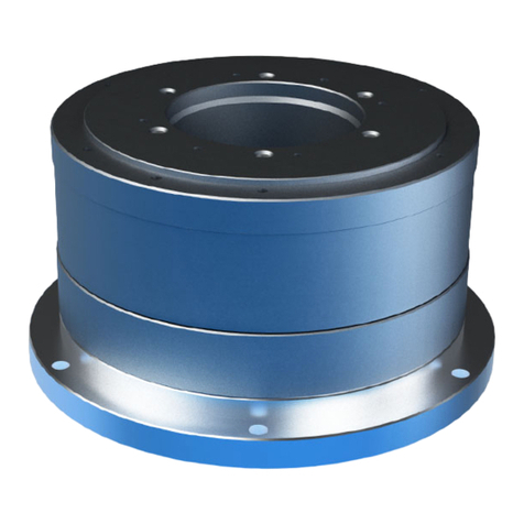
Flat Hollow Shaft AC Servo Motors
compatible with Mitsubishi Electric
MELSERVO-J4 series
MMA s eries manual
ISO14001
ISO9001

Introduction
Introduction
Thank you for purchasing our MMA series AC servo motor.
Incorrect handling or improper use of this product may result in unexpected accidents or a shorter
product life. Read this manual carefully and use the product correctly so that the product can be used
safely for many years.
The information contained in this manual is subject to change without notice.
Company names and product names in this document are generally registered trademarks or
trademarks of their respective companies.
Keep this manual in a convenient location and refer to it whenever necessary in operating or
maintaining the product.
The end user of the product should have a copy of this manual.

SAFETY GUIDE
1
SAFETY GUIDE
To use this product safely and correctly, be sure to read the SAFETY GUIDE and other parts of this
document carefully and fully understand the information provided herein before using the product.
NOTATION
Important safety information you must note is provided herein. Be sure to observe these instructions.
Indicates a potentially hazardous situation, which, if not avoided, could result
in death or serious personal injury.
Indicates a potentially hazardous situation, which, if not avoided, may result in
minor or moderate personal injury and/or damage to the equipment.
Indicates what should be performed or avoided to prevent non-operation or
malfunction of the product or negative effects on its performance or function.
LIMITATION OF APPLICATIONS
The equipment listed in this document may not be used for the applications listed below:
・Space equipment
・Aircraft, aeronautic equipment
・Nuclear equipment
・Household apparatus
・Vacuum equipment
・Automobile, automotive parts
・Amusement equipment, sport equipment, game machines
・Machines or devices acting directly on the human body
・Instruments or devices to transport or carry people
・Apparatus or devices used in special environments
If the above list includes your intended application for our products, please consult us.
If this product is utilized in any facility in which human life is
at stake or that may incur material losses, install safety
devices so that accidents do not occur even when the output
control is disabled due to damage.
WARNING
CAUTION
CAUTION

SAFETY GUIDE
2
SAFETY NOTE
ITEMS YOU SHOULD NOTE WHEN USING THE MOTOR
CAUTIONS RELATED TO THE DESIGN
Always use the motor under the specified conditions:
The motor is designed to be used indoors. Observe the following conditions:
・Ambient temperature: 0 to 40 ℃
・Ambient humidity: 20 to 80 % RH (no condensation)
・Vibration: Max. 25 m/s2
・No contamination by water or oil
・No corrosive or explosive gas
Always follow the instructions in the related manuals to
install the motor in the equipment.
・Follow the instructions in the manual to ensure that the center of the motor
is aligned with the center of the paired unit.
・Improper alignment may cause vibration or damage to the output shaft.
OPERATIONAL PRECAUTIONS
Do not exceed the allowable torque.
・Do not apply a torque exceeding the maximum torque.
・Be aware that, if arms directly attached to the output shaft are hit, the output
shaft may become uncontrollable.
Never connect cables directly to a power supply socket.
・Motors must be connected to the proper servo amplifier to operate.
・Do not connect a commercial power supply directly to the motor. Failure to
observe this caution may damage the motor, possibly resulting in a fire.
Do not apply impacts and shocks to the motor.
・Do not tap the motor with a hammer or other tool because an encoder is
connected directly to the motor.
・If the encoder is damaged, the motor may become uncontrollable.
Do not pull the cables.
・Pulling the cables can damage connectors, causing the motor to become
uncontrollable.
CAUTION
WARNING

SAFETY GUIDE
3
ITEMS YOU SHOULD NOTE WHEN USING THE SERVO AMPLIFIER
Read the related manuals to ensure safe operation. For details on the related
manuals, refer to the [Related manual] (P6).
Be sure to read the “MELSERVO-J4 SERIES AC SERVO SAFETY GUIDE”, which
comes together with the servo amplifier, before using this product.
OPERATIONAL PRECAUTIONS
Never change any wiring while the power is active.
Make sure that the power is not active before servicing the products. Failure to
observe this caution may result in an electric shock or uncontrollable operation.
Do not touch the terminals for at least 5 minutes after turning
OFF the power supply.
・Even after the power supply is turned OFF, electric charge remains in the
servo amplifier. In order to prevent electric shock, perform inspections 5
minutes or more after the power supply is turned OFF.
・When installing, make sure that the inner electronic components are hard to
reach.
DISPOSAL
The motor and servo amplifier must be disposed of as
industrial waste.
When disposing of the motor or servo amplifier, disassemble it as much as
possible, separate parts according to the material description (if indicated), and
dispose of them as industrial waste.
WARNING
CAUTION

4
Contents
SAFETY GUIDE .................................................................................................. 1
NOTATION .............................................................................................................1
LIMITATION OF APPLICATIONS............................................................................1
SAFETY NOTE ......................................................................................................2
Contents .............................................................................................................. 4
Related manual .................................................................................................... 6
Conformance to overseas standards..................................................................... 6
Chapter 1 Outlines
1-1 Outlines ....................................................................................................... 1-1
1-2 Combinations with servo amplifier and extension cables............................. 1-2
1-3 Model ......................................................................................................... 1-4
1-4 Specifications............................................................................................... 1-5
1-5 Holding brake............................................................................................... 1-7
1-6 External dimensions..................................................................................... 1-8
1-7 Mechanical accuracy.................................................................................. 1-12
1-8 Detector specifications (Absolute encoder)................................................ 1-13
1-9 Rotation direction ....................................................................................... 1-14
1-10 Shock resistance...................................................................................... 1-15
1-11 Resistance to vibration ............................................................................. 1-16
1-12 Operable range ........................................................................................ 1-17
1-13 Cable specifications ................................................................................. 1-19
Motor cable specifications .................................................................................1-19
Encoder cable specifications .............................................................................1-20
Chapter 2 Selection guidelines
2-1 MMA series selection ................................................................................... 2-1
Allowable load inertia moment.............................................................................2-1
2-2 Verifying and examining load weights .......................................................... 2-2
2-3 Examining the operating status.................................................................... 2-3
Examining motor rotational speed .......................................................................2-3
Calculating and examining load inertia moment...................................................2-3
Load torque calculation .......................................................................................2-4
Acceleration time and deceleration time ..............................................................2-5
Evaluating effective torque and average rotational speed....................................2-6

Contents
5
Chapter 3 Installing the motor
3-1 Receiving inspection .................................................................................... 3-1
Inspection procedure...........................................................................................3-1
3-2 Notices on handling...................................................................................... 3-2
Installation and transmission torque ....................................................................3-2
Precautions on installation...................................................................................3-3
Use of positioning pins ........................................................................................3-4
Motor material .....................................................................................................3-4
3-3 Location and installation............................................................................... 3-5
Environment of location.......................................................................................3-5
Installation ...........................................................................................................3-6
Chapter 4 Options
4-1 Options ....................................................................................................... 4-1
Cable taken out from side face (option code: Y) ..................................................4-1
Extension cables .................................................................................................4-2
Appendix
A-1 Unit conversion............................................................................................ 5-1
A-2 Calculating inertia moment .......................................................................... 5-3
Formulas of mass and inertia moment.................................................................5-3
Inertia moment of cylinder ...................................................................................5-5

Related manual
6
Related manual
The related manual is listed below. Use it as a reference as necessary.
Title
Document No.
Description
Obtaining method
MR-J4-_B_(-RJ)
SERVO AMPLIFIER
INSTRUCTION
MANUAL
SH-030098
The information on how to use the
"MR-J4-□B-S033" servo amplifier in
combination with the MMA series is
provided.
Can be downloaded from the
Mitsubishi Electric website.
MR-J4-□B-S033
PRODUCT
SPECIFICATIONS
BCN-B72000-090
The precautions for combining the
"MR-J4-□B-S033" servo amplifier
with the MMA series are provided.
Obtain by giving the manual
number to the supplier or
store where you purchased
your servo amplifier.
Conformance to overseas standards
The MMA series motors are compliant with the following overseas standards.
UL standards
UL1004-1, UL1004-6 (File No. E243316)
CSA standards
C22.2 No.100
European Low Voltage EC Directives
EN60034-1, EN60034-5
UL nameplate sticker
According to the UL1004-1, UL1004-6 (File No. E243316) standards, the following specifications are
indicated on the MMA series motors.
Nameplate
field
Description
(1)
Output [W] at point A on the graph below
(2)
Voltage [V] between motor wires at point A on the
graph below
(3)
Allowable continuous current [A]
(4)
Rotational speed at point A on the graph below [r/min]
(5)
Current fundamental frequency [Hz] at point A on the
graph below
(6)
Allowable ambient temperature [
℃
]
(7)
Number of phases
(1)
(2)
(3)
(4)
(5)
(6)
(7)
UL nameplate sticker
Rated torque
A
Motion range during
acceleration and deceleration
Aluminum radiation plate: 320×320×16 [mm]
Continuous motion
range
Rotation speed [r/min]
Torque [N
・
m]

Conformance to overseas standards
7
The values displayed on the name plate for each model are shown below.
Model
Item
MMAB09
(1) Output at point A W 251
(2) Voltage at point A V 136
(3) Allowable continuous current
A
2.5
(4) Speed at point A
r/min
3000
(5) Frequency at point A
Hz
250
(6) Allowable ambient temperature
℃
40
(7) Number of phases
-
3
Model
Item
MMAB12
(1) Output at point A
W
406
(2) Voltage at point A
V
129
(3) Allowable continuous current A 4.2
(4) Speed at point A r/min
2500
(5) Frequency at point A
Hz
208
(6) Allowable ambient temperature ℃40
(7) Number of phases - 3
Model
Item
MMAB15
(1) Output at point A W 754
(2) Voltage at point A
V
125
(3) Allowable continuous current
A
7.8
(4) Speed at point A
r/min
2000
(5) Frequency at point A
Hz
167
(6) Allowable ambient temperature
℃
40
(7) Number of phases
-
3
Model
Item MMAA21A
(1) Output at point A
W
1320
(2) Voltage at point A
V
100
(3) Allowable continuous current A 20.0
(4) Speed at point A r/min
1000
(5) Frequency at point A
Hz
133
(6) Allowable ambient temperature ℃40
(7) Number of phases
-
3

Conformance to overseas standards
8

Chapter 1
Outlines
This chapter explains the features, functions and specifications of the motor.
1-1 Outlines ·············································································· 1-1
1-2 Combinations with servo amplifier and extension cables················ 1-2
1-3 Model················································································· 1-4
1-4 Specifications······································································· 1-5
1-5 Holding brake······································································· 1-7
1-6 External dimensions ······························································ 1-8
1-7 Mechanical accuracy ··························································· 1-12
1-8 Detector specifications (Absolute encoder) ······························· 1-13
1-9 Rotation direction································································ 1-14
1-10 Shock resistance······························································· 1-15
1-11 Resistance to vibration ······················································· 1-16
1-12 Operable range································································· 1-17
1-13 Cable specifications··························································· 1-19

1-1 Outlines
1-1
Outlines
1
Appe
1-1 Outlines
All MMA series AC servo motor models feature a hollow bore structure and compact design and they
can be controlled with the SSCNETIII/H when combined with the Mitsubishi Electric AC servo amplifier
MELSERVO-J4 series. Wires, pipes, ball screws, or laser beams go through the hollow bore depending
on the mechanism design required for your applications.
MMA series AC servo motors play an important role in driving various factory automation (FA)
equipment, such as robot joints, alignment mechanisms for semi-conductors and LCD devices, ATC of
metal-cutting machines, printing machine roller drives, etc.
Comes standard with a 17-bit magnetic absolute encoder
The MMA series AC servo motors are equipped with a highly reliable 17-bit magnetic absolute
encoder* with safety function. The serial communication requires fewer cables and provides not only a
multi revolution counting function which is a must-have feature of motors, but it also has an internal
backup battery to retain absolute positions even when the encoder cable is disconnected briefly.
The encoder also constantly compares two sets of detected angles. If any abnormality is found, the
encoder's built-in failsafe function outputs a signal to the host system. This helps you build a safe
system.
◆Supporting a combination with MELSERVO-J4 amplifiers
Combination with Mitsubishi Electric MELSERVO-J4 amplifiers is now available. It can be controlled
using the SSCNETIII/H high-speed motion network.

1-2 Combinations with servo amplifier and extension cables
1-2
Outlines
1
Appe
1-2
Combinations with servo amplifier and extension cables
The combinations of MMA motors, MR-J4-_B-S033 servo amplifiers, and extension cables are as
follows:
MMAB09 MMAB12 MMAB15 MMAA21A
SSCNETIII/H type
MR-J4-
60B-S033
MR-J4-
100B-S033
MR-J4-
200B-S033
MR-J4-
500B-S033
Extension
cables
(option)
Motor wire EWD-MB**-A06-TMC-M EWD-MB**-D09-
TMC-M2
Encoder wire
Note 1
MR-EKCBL□M-H (Long flex life product)
or
MR-EKCBL□M-L (Standard product)
** and □in the extension cable model indicates the cable length. See below for details.
Motor wire : 02 = 2 m, 05 = 5 m, 10 = 10 m
Encoder wire : 2 = 2 m, 5 = 5 m, 10 = 10 m
For details on encoder wires, contact Mitsubishi Electric customer support.
Note 1: When connecting the encoder wires MR-EKCBL□M-* and MMAA21A, please use the encoder
connector converter cable that comes with the motor.
The MR-J4-_B-S033 servo amplifier parameters (PA17: Motor series, PA18: Motor type) are set for the
above combination. For parameters not covered in this section, refer to [Related manual] (P6).

1-2 Combinations with servo amplifier and extension cables
1-3
Outlines
1
Appe
No.
Abbreviation
(Note) Name and function
Default
value
(units)
Setting
range
PA17
*MSR
Servo motor series setting
When driving MMA motor, select the motor type with [Pr.PA17] and
[Pr.PA18].
Set at the same time as [Pr.PA18].
For the setting values, refer to the following table.
0000h
0000h
to
FFFFh
PA18
*MTY
Motor type setting
When driving MMA motor, select the motor type with [Pr.PA17] and
[Pr.PA18].
Set at the same time as [Pr.PA17].
For the setting values, refer to the following table.
Motor series Combined servo
amplifier
Parameters
[Pr.PA18]
set value
MMAB09 MR-J4-60B-S033 09C9
MMAB12 MR-J4-100B-S033 0CC9
MMAB15 MR-J4-200B-S033 0FC9
MMAA21A MR-J4-500B-S033 15C9
0000h 0000h
to
FFFFh
Note: * The set values become effective when the servo amplifier power supply is connected.
Motor series
Parameters
[Pr.PA17]
set value
MMAB09
00E1
MMAB12
MMAB15
MMAA21A

1-3 Model
1-4
Outlines
1
Appe
1-3 Model
The model names for the MMA series motors and how to read the symbols are explained below.
Model example:
MMA B 09 A 200 - 16 S17b A - C Y - SP
(1) (2) (3) (4) (5) - (6) (7) (8) - (9) (10) - (11)
(1) Model: MMA series AC servo motor
(2) Motor version symbol
A Model No. 21A
B Model Nos. 09, 12, 15
(3) Model Nos.: 09, 12, 15, 21A
(4) Brake
A Without brake
B With brake
(5) Applicable servo amplifier input voltage
200 200 V
(6) Encoder format
16 Conforming to Mitsubishi format, transmission rate: 2.5 Mbps, 1-on-1 connection
(7) Encoder type, resolution
S17b 17-bit multi-turn absolute encoder, 131072 pulses/revolution
(8) Encoder phase angle: Phase difference between the voltage induced in motor phase U and
absolute origin
A 0 degree
(9) Connector specification
C With standard connector
N Without connector
(10) Option symbol
Y Cable taken out from the side
(It is not available for model No. 21A.)
(11) Special specification
No description Standard product
SP Special specification product

1-4 Specifications
1-5
Outlines
1
Appe
1-4 Specifications
The specifications of the MMA series motors are shown below.
Model
Item MMAB09 MMAB12 MMAB15 MMAA21A
Compatible servo amplifier MR-J4-60B-
S033
MR-J4-100B-
S033
MR-J4-200B-
S033
MR-J4-500B-
S033
Input power supply V 200 200 200 200
Rated output W 251 406 754 1320
Maximum momentary
torque*1
N
・
m 3.0 6.6 13 45
kgf
・
m 0.31 0.67 1.33 4.59
Rated torque*1*2 N
・
m 0.80 1.55 3.60 12.6
kgf
・
m 0.082 0.158 0.367 1.29
Max. rotational speed*1 r/min 5600 4800 4000 3000
Rated rotational speed r/min 3000 2500 2000 1000
Instantaneous max. current*1 A 8.9 18 29 75
Rated current*1*2 A 2.5 4.2 7.8 20.0
Torque constant*1 N
・
m/A 0.41 0.44 0.54 0.72
kgf
・
m/A 0.042 0.045 0.055 0.073
EMF constant*3 V/(r/min) 0.043 0.046 0.057 0.075
Phase resistance (20
℃
) Ω1.2 0.33 0.19 0.028
Phase inductance mH 3.0 1.4 1.2 0.29
Inertia moment
Values in
parentheses are for
models with a
brake.
GD2/4 ×10-4 kg
・
m21.78 6.45 15.8 125
(2.16) (6.83) (19.8) (141)
J ×10-4kgf
・
cm
・
s218.2 65.8 161 1280
(22.1) (69.7) (202) (1444)
Allowable radial load
(when stationary)
N 800 1200 2400 4500
kgf 81.6 122 245 459
Allowable axial load
(when stationary)
N 2400 3600 5000 14000
kgf 245 367 510 1429
Rated radial load
(at rated rotational speed)
N 185 233 530 1040
kgf 18.9 23.8 54.1 106.1
Rated axial load
(at rated rotational speed)
N 105 130 180 880
kgf 10.7 13.3 18.4 89.8
Encoder type Absolute encoder
Encoder resolution
Single-turn
detector
217 (131072)
Multi-turn
detector
*4
216 (65536)
Mass
Values in parentheses are for
models with a brake.
kg 2.0 3.4 5.5 17.5
(2.1) (3.8) (6.2) (19.7)

1-4 Specifications
1-6
Outlines
1
Appe
Environmental conditions*6
Operating temperature: 0 to 40 ℃/Storage temperature: -20 to 60 ℃
Service/storage humidity: 20 to 80 % RH (no condensation)
Resistance to vibration: 25 m/s2 (frequency: 10 to 400 Hz)
Resistance to impact: 300 m/s2 *5
No dust, metal powder, corrosive gas, inflammable gas, or oil mist.
To be used indoors, no direct sunlight.
Altitude: less than 1000 m above sea level
Motor insulation
Insulation resistance: 100 MΩ or more (500 VDC insulation tester)
Dielectric strength: 1500 VAC/1 min
Insulation class: A
Mounting direction Can be installed in any direction.
Protection structure Totally enclosed self-cooled type (IP54)
The table above shows the typical values.
*1: This displays representative characteristics for when combined with a dedicated amplifier (driven using an ideal
sine wave).
*2: Values after the temperature has risen and saturated when installed on the following aluminum radiation plates.
MMAB09 : 350×350×18 [mm]
MMAB12 : 400×400×20 [mm]
MMAB15 : 500×500×25 [mm]
MMAA21A : 650×650×30 [mm]
*3: Value of the phase-induced voltage constant multiplied by 3.
*4: The multi-turn detector range is -32768 to 32767.
*5: For testing conditions, refer to [1-10 Shock resistance] (P1-15) and [1-11 Resistance to vibration] (P1-16).
Motor operation is not guaranteed in applications where vibrations and impacts are continuously applied for a
long period of time.
*6: For details, refer to [3-3 Location and installation] (P3-5).

1-5 Holding brake
1-7
Outlines
1
Appe
1-5 Holding brake
The brakes equipped on MMA series motors are used to hold the motor shaft in place when the power
is cut off. With some models (MMAB09, 12), the motor's built-in circuit controls the voltage supplied to
the brake in order to reduce the power consumption while the brake is actuated.
Always use a DC power supply that has a proper brake excitation voltage and is capable of outputting
enough current during suction.
Specifications
Model
Item
MMAB09 MMAB12 MMAB15 MMAA21A
Type Dry non-excitation actuation type
Power-saving control Yes No
Brake excitation voltage V 24 VDC ± 10 % (no polarity) *1
Current consumption
during suction
A 0.8*2 0.8*2 0.7 0.9
Current consumption
during holding
A 0.3 0.3 0.7 0.9
Holding torque N
・
m 1.0 2.0 4.0 15
kgf·m 0.102 0.204 0.408 1.53
Allowable number of
normal brakings
*3
100000 times
Allowable number of
emergency stops
*4
200 times
*1: The power supply for the brake is not included in the product. Use a power supply that is capable of outputting
enough current during brake suction.
*2: The duration the current is supplied during suction is 0.5 second or less for the power supply of 24 VDC ± 10 %.
*3: When the brake is activated at the rotational speed of 150 r/min or less.
*4: When the brake is activated at the rotational speed of 3000 r/min, provided that the inertia moment of load is 3
times or less than that of the motor.
The holding brake cannot be used for deceleration.
Do not use the holding brake more than the allowable number of normal
brakings (100000 times at the rotational speed of 150 r/min or less) or allowable
number of emergency stops (200 times at the rotational speed of 3000 r/min,
provided that the inertia moment of load is 3 times or less than that of the
motor).
Exceeding the allowable number of normal brakings and allowable number of
emergency stops may cause the holding torque to decrease and consequently
become unusable as a brake.
WARNING

1-6 External dimensions
1-8
Outlines
1
Appe
1-6 External dimensions
The external dimensions of the MMA series motors are shown below.
MMAB09 (with/without brake)
Unit [mm] (third angle projection)
Note: For details on external dimensions, see our illustrated specifications.
Tolerances may vary with the product manufacturing method (foundry piece, machine-finished good).
Contact us for the differential range of the size that is not described.
Encoder cable
Motor cable
(Cable outer diameter:
φ5.6)
(Cable outer diameter: φ7.7)
Motor connector
Encoder connector
Housing
Pin contact
Pin contact
Housing
Tab contact
Clamp
R0.4 or less
R0.4 or less
15 or less

1-6 External dimensions
1-9
Outlines
1
Appe
MMAB12 (with/without brake)
Unit [mm] (third angle projection)
Note: For details on external dimensions, see our illustrated specifications.
Tolerances may vary with the product manufacturing method (foundry piece, machine-finished good).
Contact us for the differential range of the size that is not described.
Encoder cable
Motor cable
Motor connector
Encoder connector
Housing
Tab contact
Clamp
Housing
Pin contact
Pin contact
R0.4 or less
R0.4 or less
15 or less
(Cable outer diameter: φ7.7)
(Cable outer diameter: φ7.7)
This manual suits for next models
4
Table of contents
Other Harmonic Drive Engine manuals
Popular Engine manuals by other brands

Harbor Freight Tools
Harbor Freight Tools Chicago Electric 40132 Assembly and operating instructions
Kohler
Kohler Courage SV470 owner's manual
Engine distributors
Engine distributors CSG 637 Operator's handbook
Volvo Penta
Volvo Penta KAD/KAMD44P Operator's manual
Kohler
Kohler KD83V16 Service and repair manual

INOXPAN
INOXPAN Pando V2350e installation manual
