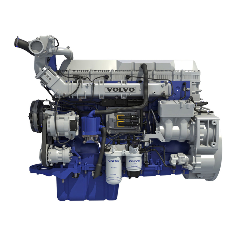
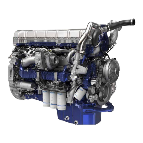
Volvo DH10A 245 User manual

1
Contents
Group 20: General
Variant description DH10A.............................. 2
Performance...................................................... 3
Specifications ................................................... 4
Wear tolerances ................................................ 15
Tightening torques............................................ 16
Special tools ..................................................... 17
Removing and installing engine ....................... 25
Servicing the engine:
– Replacing fuel filters ................................... 31
– Topping-up oil............................................. 32
– Replacing oil filters ..................................... 33
– Replacing coolant filter ............................... 33
– Condition test, compression test.................. 34
– Charge pressure ........................................... 35
– Fuel feed pressure........................................ 37
– Oil pressure ................................................. 38
– Pressure-testing cooling system .................. 38
– Valve tappets, valve timing ......................... 38
– Valve adjustment......................................... 39
Group 21: Engine
Detailed list of contents .................................... 40
Cylinder head ................................................... 41
Cylinder liners, pistons, connecting rods ......... 51
Cylinder block, crank mechanism .................... 58
Group 22: Lubricating system
Detailed list of contents .................................... 79
Oil pump........................................................... 83
Oil cooler .......................................................... 87
Group 23: Fuel system
Detailed list of contents .................................... 88
Injection pump.................................................. 91
Injection timer .................................................. 92
Injectors ............................................................ 94
Group 25: Inlet and exhaust systems
Detailed list of contents .................................... 110
Air cleaner ........................................................ 111
Intercooler, pressure-drop indicator ................. 112
Starting pre-heater ............................................ 113
Turbocompressor.............................................. 115
Exhaust pressure governor ............................... 125
Group 26: Cooling system
Detailed list of contents .................................... 127
Main thermostat................................................ 130
Coolant pump ................................................... 131
Intercooler ........................................................ 135
Cooling fan ....................................................... 137
High coolant temperature ................................. 141
Fan drive........................................................... 143
Group 27: Engine controls
Detailed list of contents .................................... 145
Description EDC .............................................. 146
EDC-components in electrical
distributor unit .............................................. 148
Fault diagnosis.................................................. 150
Troubleshooting................................................ 155
Order number: TP 16031/1

2
Engine DH10A
Basic engine Type Specific characteristics and areas of use Bus type
Variants
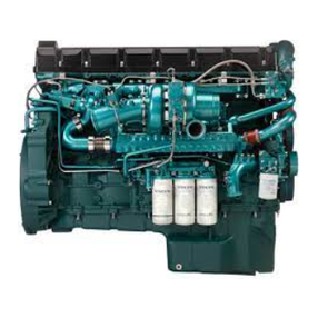
Common characteristics: The DH10A-series is largely
based on the earlier THD104 engine. Characteristics:
Horizontal design, turbocompressor feed, 9.6 liter dis-
placement. Single circuit coolant-intercooler, separated
from the ordinary coolant system. Lube system with
two full-flow filters and piston cooling from oil sprayed
onto the pistons from underneath. Piston peaks have
been changed but still build on the re-entry model, that
is, a more favourable air rotation and thereby a more
complete combustion. The injection system is electron-
ically controlled (EDC). Injection pressure has been
raised as a result of changes in the injection pump.
Other nozzles also contribute to better combustion, re-
sulting in lower emissions and lower fuel consumption.
Net output has been measured in accordance with ISO 1585 and SAE J 1349. Smoke requirements met according to ECE/
EEC and the Swedish regulations. DH10A fulfils smoke requirements as per 91/542/EEC, Level B (Euro 2) (EC96).
180 kW.
Low emissions for city buses. Wastegate and water-cooled turbo for
flatter torque curve.
210 kW. Low emissions engine for city buses, e.g., articulated buses,
bogie buses. Wastegate and water-cooled turbo for flatter torque
curve.
250 kW.
Engine for Japan. Low Nox-value as per Japanese requirements.
Altered a. Otherwise similar to 360.
260 kW.
Engine for Taiwan and other countries. Altered a and no injection
timer. Otherwise similar to 360.
265 kW.
High-output engine for tourist coaches and long-distance buses.
Large number produced. Injection pump has a timer that is electroni-
cally controlled. Saves fuel at high power output.
DH10A 245
DH10A 285
DH10A 345
DH10A 350
DH10A 360
B10B, L, B10M
1996–
B10B, L, B10M
1996–
B10M 1996–
B10M 1996–
B10M, B10B
1996–

3
Performance
DH10A 245, 285 DH10A 345, 350, 360
kW
220
200
180
160
140
120
100
80
60
1000 1200 1400 1600 1800 2000 2200 2400rpm
Output Effekt Leistung Puissance Potentia
Nm
1200
1000
800
Torque Vridmoment Drehmoment Couple Par motor
285 EC96
245 EC96
285 EC96
245 EC96
kW
280
260
240
220
200
180
160
140
120
1000 1200 1400 1600 1800 2000 2200 2400rpm
Output Effekt Leistung Puissance Potentia
Nm
1600
1400
1200
Torque Vridmoment Drehmoment Couple Par motor
345 J96
350 TW95
360 EC96
345 J96
350 TW95
360 EC96

4
Specifications
General
ENGINE DH10A
Type designation ............................ 245 285 345 350 360
Net output* kW/hp ......................... 180/245 210/285 254/345 255/350 265/360
at speed r/s / r/min ...................... 33/2000 33/2000 33/2000 33/2000 34.2/2050
Max. torque Nm/kpm
at 20 r/s (1200 r/min).................. 1050/107 1200/122 1440/146 1500/153 1500/153
* Net as per ISO 1585.
Number of cylinders ..................................................... 6
Bore .............................................................................. 120.65 mm
Stroke............................................................................ 140 mm
Displacement ................................................................ 9.6 dm3(9.6 liter)
DH10A DH10A
245, 285 345, 350, 360
Compression ratio 20:1 18:1
Firing sequence............................................................. 1-5-3-6-2-4
Direction of rotation (B10M frontal view,
B10B rear view, engine installed in bus) ................ Clockwise
Low idle........................................................................ 8.8±0.8 r/s 8.8±0.8 r/s
(530±50 r/min) (530±50 r/min)
High idle ....................................................................... 36.6±0.8 r/s 36.6±0.8 r/s
(2200±50 r/min) (2200±50 r/min)
De-regulating speed begins at ...................................... 34.8 r/s 38.8±0.8 r/s
(2085 r/min) (2330±50 r/min)
Weight, engine with flywheel, flywheel housing and
starter motor, approx ............................................... 960–980 kg
Maximum length x width x height ............................... 1460 x 1375 x 590 mm

5
Engine block
Cylinder head
Type ...................................... 1 per cylinder
Height,new ........................... 114.85–115.15 mm
after machining min. 114.65 mm
Groove for cylinder liner,
width ..................................... 3.4±0.05 mm
depth ..................................... 3.0±0.3 mm
Cylinder head bolts
Number/cylinder head .......... 4
Dimension thread.................. 3/4"–10 UNC
Length................................... 200 mm
Cylinder block
Height, upper block face –
crankshaft centre (A) min. 438.8 mm
Height, lower block face –
crankshaft centre (B) ........ 120 mm
Length................................... 990 mm
Piston rings
Compression rings
Number .................................... 2
Piston-ring clearance in groove,
upper compression ring ...... 0.13 mm
lower compression ring ...... 0.09 mm
Piston-ring gap in ring
opening 1st ring...................... 0.50 mm
2nd ring .................... 0.70 mm
Oil scraper ring
Number .................................... 1
Piston-ring clearance in ring
opening ................................ 0.4 mm
Piston-ring clearance in groove 0.05 mm
Gudgeon pins
Clearance, gudgeon pin –
connecting-rod bushing ....... 0.03 mm
Gudgeon pin diameter stnd...... 51.998–52.000 mm
Gudgeon pin hole diameter
in piston ............................... 52.005–52.013 mm
Valve Mechanism
Valves
Disc diameter
Inlet..................................... 50 mm
Exhaust ............................... 46 mm
Stem diameter
Inlet..................................... min. 10.91 mm
Exhaust ............................... min. 10.90 mm
Max. permitted wear................ 0.07 mm
Valve seat angle/valve edge
Inlet..................................... 29.5°/min. 2.4 mm
Exhaust ............................... 44.5°/min. 1.7 mm
Seat angle in cylinder head
Inlet..................................... 30°
Exhaust ............................... 45°
Cylinder liner (pistons and piston rings) should be re-
placed with 0.40–0.45 mm wear or if oil consumption
is abnormally high.
Pistons
Height, above block face ...... max. 0.70 mm
No. of ring grooves............... 3
Piston clearance, fully
cast piston ......................... 0.12–0.15 mm
Front marking ....................... arrow faces forwards
Cylinder liners
Type ...................................... Wet, replaceable
Height, total .......................... 287 mm
Step edge height above
block face.......................... 0.14–0.20 mm
INLET EXHAUST
0,14 - 0,20 mm
0.14–0.20 mm

6
Valve clearance, cold engine
Inlet...................................... 0.40 mm
Exhaust ................................ 0.70 mm
Depth (meas. D)
Inlet...................................... 8.8–8.9 mm
Exhaust ................................ 11.8–11.9 mm
Recess bottom radius (meas. R)
Inlet...................................... 0.5–0.8 mm
Exhaust ................................ 0.5–0.8 mm
Meas. between valve disc
and cylinder head face should
be min.
Inlet...................................... 0.05–0.50 mm
Exhaust ................................ 1.2–1.7 mm
The valve seat may be ground
so far that the distance from the
valve disc (new valve) to the
cylinder head face is max.:
Inlet...................................... 1.5 mm
Exhaust ................................ 2.5 mm
If the distance is greater, replace the seats.
Valve guides
Inside diameter
Inlet...................................... 11.02–11.04 mm
Exhaust ................................ 11.02–11.04 mm
Height above cylinder head
spring face
Inlet...................................... 20 mm
Exhaust ................................ 21 mm
Max. permitted clearance between
valve stem and valve guide
Inlet...................................... 0.15 mm
Exhaust ................................ 0.25 mm
Valve springs
Outer valve spring
Length, off-load ........................ 61 mm
With 300–390 N
(30–39 kp) load......................... 49.6 mm
Inner valve spring
Length, off-load ........................ 53 mm
With 80–170 N
(8–17 kp) load........................... 42.6 mm
INLET
EXHAUST
Adjust the valves as follows:
When no. 1 cyl. piston is at T.D.C. after compression,
adjust valves 1, 2, 4, 5, 8 and 9.
When no. 6 cyl. piston is at T.D.C. after compression,
adjust valves 3, 6, 7, 10, 11 and 12.
Valve seat inserts
Outer diameter (meas. A) standard
Inlet...................................... 54 mm
Exhaust ................................ 49 mm
Oversize
Inlet...................................... 54.2 mm
Exhaust ................................ 49.2 mm
Height (meas. B)
Inlet...................................... 6.8 mm
Exhaust ................................ 9.5 mm
Recess for valve seat inserts
Diameter (meas. C), standard
Inlet...................................... 54.00–54.03 mm
Exhaust ................................ 49.00–49.025 mm
Diameter (meas. C), oversize
Inlet...................................... 54.20–54.23 mm
Exhaust ................................ 49.20–49.225 mm

7
1. Crankshaft gear
2. Intermediate gear
3. Camshaft gear
4. Injection pump drive gear
5. Compressor drive gear
6. Intermediate gear for oil pump/coolant pump
7. Drive gear for oil pump/coolant pump
8. Servo pump drive gear
Camshaft
Drive ......................................... Gear
No. of bearings ......................... 7
Bearing journal diameters, min.
Front bearing journal ........... 68.94 mm
2nd ....................................... 66.56 mm
3rd........................................ 64.17 mm
4th ........................................ 63.39 mm
5th ........................................ 60.99 mm
6th ........................................ 60.21 mm
7th ........................................ 56.24 mm
End float, max. ......................... 0.18 mm
Radial clearance (same for all
bearings) max. ...................... 0.079 mm
Max. permitted out-of-round
(new bearings) ..................... 0.05 mm
Bearings, max. permitted wear . 0.05 mm
Lift height min., Camshaft
Inlet...................................... 8.4 mm
Exhaust ................................ 9.0 mm
Valve tappets, max. permitted
radial clearance.................... 0.08 mm
Checking camshaft setting (cold
engine and valve clearance = 0)
At 10°flywheel A.T.D.C. no. 1
cyl. inlet valve should open ...... 4.2–4.8 mm
Max. valve lift:
inlet ...................................... 13.3 mm
exhaust................................. 14.3 mm
Min. valve lift:
inlet ...................................... 13.0 mm
exhaust................................. 14.0 mm
Camshaft bearings
Bearing bores
Front bearing ....................... 69.050–69.075 mm
2nd ....................................... 66.675–66.700 mm
3rd........................................ 64.287–64.312 mm
4th ........................................ 63.500–63.525 mm
5th ........................................ 61.112–61.137 mm
6th ........................................ 60.325–60.350 mm
7th ........................................ 56.350–56.375 mm
Wear max. ........................... 0.050 mm
Timing gears
Number of teeth:
crankshaft gear (1)................... 30
intermediate gear (2) ............... 53
injection pump drive gear (4) .. 60
servo pump drive gear (8) ....... 19
camshaft gear (3) ..................... 60
compressor drive gear (5)........ 26
intermediate gear for oil pump
and coolant pump (6)............... 48
drive gear for oil pump and
coolant pump (7) ..................... 21
Backlash, max............................... 0.17 mm
Bearing sleeve, intermediate gear,
diam., max. .............................. 92.106 mm
Bushing, intermediate gear,
diam., max. .............................. 92.158 mm
Radial clearance for intermediate
gear max. ................................. 0.082 mm
Axial clearance for intermediate
gear max. ................................. 0.15 mm

8
Crank Mechanism
Crankshaft
Length....................................... 1154 mm
Crankshaft, end float, max........ 0.4 mm
Main bearings, radial
clearance, max. ......................... 0.14 mm
The crankshaft is nitrocarburised or induction-hard-
ened. NOTE: A nitrocaburised crankshaft may be
ground max. to 2nd undersize. With deeper grinding
the crankshaft must be re-nitrocarburised.
Main bearing journals
Diameter (Ø) for machining
standard ............................. 99.978–100.000 mm
undersize 0.25 mm ........... 99.724–99.746 mm
0.50 mm ........... 99.470–99.494 mm
0.75 mm ........... 99.216–99.238 mm
1.00 mm ........... 98.962–98.984 mm
1.25 mm ........... 98.708–98.730 mm
Main bearing journals
out-of-round (new) ............ max. 0.006 mm
wear out-of-round.............. max. 0.08 mm
taper ................................... max. 0.05 mm
Width axial journal pin (A)
standard ............................ 45.975–46.025 mm
Oversizes
0.2 mm
(axial bearing 0.1 mm) .. 46.175–46.225 mm
0.4 mm
(axial bearing 0.2 mm) .. 46.375–46.425 mm
0.6 mm
(axial bearing 0.3 mm) .. 46.575–46.625 mm
Fillet radius (R) ...................... 3.75–4.00 mm
Thrust washers (axial bearing)
Thickness (B), standard ............... 2.312–2.362 mm
oversize 0.1 mm ...... 2.412–2.462 mm
0.2 mm ...... 2.512–2.562 mm
0.3 mm ...... 2.612–2.662 mm
0.4 mm ...... 2.712–2.762 mm
Main bearing shells
Diameter, bearing shell seat
in block ............................ 104.978–105.003 mm
Thickness (D),
standard ........................... 2.447 mm
undersize 0.25 mm .......... 2.574 mm
0.50 mm .......... 2.701 mm
0.75 mm .......... 2.828 mm
1.00 mm .......... 2.955 mm
1.25 mm .......... 3.082 mm

9
Big-end bearing journals
Diameter (Ø) for machining
standard ............................... 86.003–86.025 mm
undersize 0.25 mm ............. 85.753–85.775 mm
0.50 mm ............. 85.503–85.525 mm
0.75 mm ............. 85.253–85.275 mm
1.00 mm ............. 85.003–85.025 mm
1.25 mm ............. 84.753–84.775 mm
Axial bearing surface width (A) 53.90–54.00 mm
Fillet radius (R) ........................ 3.75–4.00 mm
Big-end bearing journals
out-of-round (new) .............. max. 0.004 mm
slitage orundhet ............. max. 0.08 mm
konicitet ............. max. 0.05 mm
Connecting-rod bearing shells
Thickness (C),
standard ............................... 2.413 mm
undersize 0.25 mm ............. 2.540 mm
0.50 mm ............. 2.667 mm
0.75 mm ............. 2.794 mm
1.00 mm ............. 2.921 mm
1.25 mm ............. 3.048 mm
Connecting rods
Length, centre crankpin seat –
centre gudgeon pin seat: ........... 277 mm
Diameter:
connecting-rod bushing ....... 57.300–57.346 mm
connecting-rod bushing
internal diameter (G) ........... 52.022–52.028 mm
Axial clearance, crankshaft –
connecting rod, max. ........... 0.35 mm
Connecting-rod bearings, radial
clearance, max. .................... 0.12 mm
Max. weight deviation for
connecting rods within
same engine ......................... 50 g
Straightness max. deviation on
100 mm measuring length ... 0.05 mm
Torsion, max. deviation on
100 mm measuring length ... 0.1 mm
Flywheel, installed
Max. permitted axial throw
(manual gearbox) measuring
radius 150 mm ..................... 0.16 mm
Ring gear on flywheel .............. 156 teeth
Flywheel casing, installed
Max. permitted axial throw for
contact surface against clutch
casing
....................................
0.13 mm
Max. permitted radial throw for
guide diameter towards clutch
casing................................... 0.19 mm

10
15773-13
Reducer valve
Spring length
Off-loaded ........................... 61 mm
Loaded with
83–86 N (8.3–8.6 kp) .......... 33 mm
Loaded with
64–67 N (6.4–6.7 kp) .......... 39 mm
By-pass valve (oil cooler)
Spring length
Off-loaded ........................... 69 mm
Loaded with
17.9 N (1.79 kp) .................. 32 mm
Loaded with
14.0 N (1.4 kp) .................... 40 mm
Relief valve (direct oil filter)
Spring length
Off-loaded ........................... 69 mm
Loaded with
16.9–18.9 N (1.69–1.89 kp) 32 mm
Loaded with
13–14 N (1.3–1.4 kp) .......... 40 mm
Oil filters
Direct oil filters
Number................................ 2
Volvo P/N............................ 466634-3
Tightening torque
(oiled sealing ring).................... 25 Nm
Lubricating system
Oil change quantity, with
oil filter ................................ approx. 40 litres
Oil pressure, operating speed ... 300–500 kPa
(3–5 bar)
Oil pressure, idling (low idle)... min. 60 kPa
(0.6 bar)
Oil quality ................................. Volvo Drain
Specification alt.
API Service CD, CE
or CCMC -D4, D5
Lube oil pump
Type .......................................... Gear-driven
Number of teeth ........................ 11
Axial play, gear wheel .............. 0.02–0.08 mm
Backlash ................................... 0.15–0.35 mm
Diameter,
bushing for pump shaft........ 18.050–18.068 mm
bearing sleeve intermediate
gear ...................................... 92.084–92.106 mm
bushing for intermediate
gear ...................................... 92.141–92.176 mm
Drive gear-bracket, distance ..... 1–1.5 mm
The temperatures refer to stable ambient temperatures.
1) Refers to synthetic or semi-synthetic oil.
NOTE! Only SAE 5W/30 may be used.
-22 -4 14 32 50 68 86 104
-30 -20 -10 0 10 20 30 40
SAE 15W/40
SAE 10W/30
SAE 5W/30
SAE 20W/30
SAE 30
SAE 40
F
C
-22 -4 14 32 50 68 86 104
-30 -20 -10 0 10 20 30 40
F
C
-15°C
-25°C
-10°C
0°C
+10°C
1
Viscosity acc. to diagram below.

11
Fuel system
Type .............................................................................. EDC (Electronic Diesel Control)
Injection pump direction of rotation, seen from
clutch side................................................................ Clockwise
Injection sequence ........................................................ 1-5-3-6-2-4
Fuel
Quality must fulfil minimum current legislation as well as national and international standards EN 590, SS-EN 590,
DIN EN 590, ASTMD 975 No. 1-D, No. 2-D, JIS KK 2204.
Injection pump
Volvo P/N ..................................................................... 425 758
Pump type ..................................................................... PE 6 P 120 A320 RS 8033
Governor type ............................................................... RE 30
Injection pump direction of rotation............................. Clockwise
Injection sequence ........................................................ 1-5-3-6-2-4
Injection pump basic setting on engine:
DH10A 345 .................................................................. 5.5±0.5°B.T.D.C.
DH10A 245, 285, 360 .................................................. 7.0±0.5°B.T.D.C.
DH10A 350 .................................................................. 9.0±0.5°B.T.D.C.
Performance check
Bus stationary
• Engine switched off
• Start key (feed selector switch) in drive position
Accelerator pedal in idle position:
Reference voltage (U ref) ............................................. 4.5–5.0 V
Control rod travel ......................................................... 0.27–0.60 V
(6.0–1.2% of U ref)
Accelertor pedal in full throttle position (incl. kickdown):
Accelrator pedal sensor ................................................ 62–70% of U ref
Turbo pressure (voltage)............................................... 1.30–1.50 V

12
Speed 1200 r/min 2000 r/min
over- over- control over- over- control
press. press. rod travel press. press. rod travel
kPa volt volt kPa volt volt
DH245 125 3.60 2.40 135 3.76 2.74
DH285 135 3.76 2.55 150 3.99 3.05
DH360 115 3.44 2.87 195 4.71 3.18
D 245 125 3.60 2.36 135 3.76 2.71
DH350 106 3.31 2.87 196 4.75 3.18
DH345 – Values not known when manual went to print.
Measuring during driving
• Fully loaded bus
• Accelerator pedal in full throttle position
Injection timer, only DH10A 345 and 360
Drive ............................................................................. Gear
No. of bearings ............................................................. 2
Bore, bearings............................................................... 67.05–67.08 mm
The injection timer alters the pump basic timing (µ) with engine at operating temp. (above 55°C), see page 97.
Feed pump
Designation................................................................... FP/KG 24 P 307
Feed pressure (depending on speed and load) .............. 100–400 kPa (1–4 bar)
Injectors DH10A 245, 285
Nozzle stand ................................................................. KBEL 117 P 73
Nozzle (Volvo P/N) ...................................................... DLLA 150 P555 (425694)
Number marking (complete injector) ........................... 555
Opening pressure .......................................................... 25 MPa
Adjusting pressure (new spring)................................... 26 MPa
No. of holes x bore. ...................................................... 6 x 0.236 mm
Injectors DH10A 345, 350, 360
Nozzle stand ................................................................. KBEL 117 P 73
Nozzle (Volvo P/N) ...................................................... DLLA 152 P571 (8194095)
Number marking (complete injector) ........................... 571
Opening pressure .......................................................... 25
Adjusting pressure (new spring)................................... 26
No. of holes x bore. ...................................................... 6 x 0.236 mm
Fuel filters
Number ......................................................................... 2
Volvo P/N ..................................................................... 466 987
+0.8
–0
+0.8
–0
+0.8
–0
+0.8
–0

13
Inlet and exhaust systems
Turbocompressor
For engine DH10 245, 285
Designation................................ HX 40 W – 8594 Z
Cooling ...................................... Water-cooled
Lubricating system .................... Pressure-
lubrication
Wastegate opening pressure ...... 155 kPa engine
speed 4.04 volts
at 2000 r/min
With control rod travel on
wastegate ................................... 1±0.3 mm
(setting)
Check value ............................... 0.4–1.5 mm
Axial clearance, rotor ................ 0.04–0.09 mm
Measuring during driving
Accelerator pedal in full throttle position and
engine at max. load: See Performance Check
Starter pre-heater
Output ........................................ 3500 W
Pressure-drop indicator
Red indication at mm VP .......... 580–720
Exhaust-pressure governor
Control pressure with warm-up
and exhaust pressure braking. 750 kPa
Cooling system
Type ........................................... Overpressure closed
Pressure valve opens at.............. approx. 50 kPa
(0.5 kp/cm2)
Coolant
Anti-freeze
Type ........................................... C
Consists of ................................. Glycol with
rustproofing
Colour ........................................ Blue-green
Volvo art no.1 kg ...................... 1128700-9
5 kg ...................... 1129701-7
235 kg .................. 1129702-5
Radial clearance at compressor
wheel.......................................... 0.33–0.50 mm
For engine DH10A 345, 350, 360
Designation................................ GT 4288 N
Lubricating system .................... Pressure-lubrication
Maximum speed (all).................
approx.1400–1800 r/s
(81 000–108 000
r/min)
Measuring with bus stationary
Accelerator pedal in idle position:
Reference voltage ...................... 4.5–5.0 V
Control rod travel ...................... 0.3–0.6 V
Turbo pressure (voltage)............ 1.30–1.50 V
Accelerator pedal in full throttle position:
Reference value ......................... 62–70% of U ref

14
Thermostats
Type .......................................... Gear-driven pump
with two pump
gears
Coolant pump
Impeller press-in depth
Fans B10M
Hydraulic-driven cooling fan
Pump, type/designation ............ Vickers PVE 19 R
Fan motor, type/designation ..... Volvo Flygmotor
F11-19
Fan speed
at engine speed 1000 r/min
and coolant temperature
under 90°C....................... approx. 700 r/min
above 94°C ...................... approx. 2000 r/min
Filter, part no. ........................... 4823936
Drive belts ................................ HC 50 1150 Lw x 2
P/N 966846
Fans B10B
Temperature-controlled cooling fan
Type ............................... Bimetal plate/
coolant coupling
Fan speed at engine speed
38.3 r/s (2300 r/min),
under +37°C ............. min. 7 r/s (420 r/min)
above +63°C ............. min. 35.7 r/s (2100 r/min)
Temperatures refer to temp. round bimetal plate.
Drive-belt driven cooling fan
Fan drive reduction................... 1:1.22
Belt type/size (4 belts included
in this drive).......................... HC 12.5 x 1550
P/N 9515805
Engine circuit (1)
Type .......................................... Piston thermostat
Number ..................................... 2
Marking .................................... 82
Opening temperature ................ 82±2°C
Fully open at ............................. 95±2°C
Heating distributor thermostat (2)
Marking .................................... 60
Opening temperature ................ 58–62°C
Fully open at ............................. approx. 77°C

15
Hydraulic-driven cooling fan
(rear-mounted)
Pump, type/designation ............ Vickers PVE 19 R
Fan motor, type/designation ..... Volvo Flygmotor
F11-19
Fan speed
at engine speed 1000 r/min
and coolant temperature
under 90°C....................... approx. 700 r/min
above 94°C ...................... approx. 2000 r/min
Filter, P/N ................................. 4823936
Drive belts
late prod............................... SPB 2380 Lw
P/N 9518424
Fan speed Engine speed
Fan B10L
Fan drive, hydraulic
Pump type/designation ............. AFGP 31.5 L
Volvo P/N ................................. 3118711
Fan motor/designation .............. Sauer Sundstrand
551/1/00888/ETC
Volvo P/N ................................. 9519828
Thermostat valve ...................... Sauer Sundstrand
553/1/09648/093
Volvo P/N ................................. 9519829
Closes at.................................... 93°C
Fan speed
Engine speed 1000 r/min. and coolant temperature:
Under 80°C ............................... approx. 300 r/min
Above 93°C .............................. approx. 1500 r/min
Wear tolerances
Cylinder head
Height, min. .............................. 114.65 mm
Max. pressure at leakage check 150 kPa
(1.5 kp/cm2)
Cylinder liners
A cylinder liner (pistons and piston rings) should be re-
newed at 0.40–0.45 mm wear or if oil consumption is
abnormally high.
Crankshaft
Max. permitted out-of-round on
main bearing and big-end
bearing journals ................... 0.08 mm
Max. permitted taper on main
bearing and big-end bearing
journals ................................ 0.05 mm
Max. crankshaft end float ......... 0.40 mm
Max. radial clearance................ 0.14 mm
Connecting rods
Straightness, max. deviation on
100 mm length measured .... 0.05 mm
Torsion, max. deviation on
100 mm length measured .... 0.1 mm
End float, max. ......................... 0.35 mm
Radial clearance, max............... 0.12 mm
Valves
Max. permitted clearance between
valve stem and valve guide
Inlet...................................... 0.15 mm
Exhaust ................................ 0.25 mm
Valve disc edge should be min.
Inlet...................................... 1.9 mm
Exhaust ................................ 1.4 mm
The valve stem insert may be ground down so
that distance from the valve disc (new valve)
to cylinder head face is max.
Inlet...................................... 2.5 mm*
Utlopp .................................. 1.5 mm
* With greater distance than above, renew inserts.
Camshaft
End play, max. .......................... 0.18 mm
Radial clearance, max............... 0.08 mm
Max. permitted out-of-round
(with new bearings) ............. 0.05 mm
Bearings, max. permitted wear . 0.05 mm
Valve tappets, max. permitted
radial clearance.................... 0.08 mm
Flywheel, installed
Max. permitted axial throw (manual gearbox)
measuring radius 150 mm ........ 0.16 mm
Coolant temperature °C

16
Tightening torques
Groups 20–21 Nm kpm
Cylinder heads (see note 1)
Main bearings ........................... 340±25 34.0±2.5
Big-end bearings....................... (see note 2)
Intermediate gear bearings........ 60 6.0
Flywheel ................................... 185 18.5
Pulley, crankshaft ..................... 60±6 6.0±0.6
Flywheel casing ........................ 140±15 14.0±1.5
Drive gear, injection pump
drive with 6 bolts ................. 33±4 3.3±0.4
Drive gear, camshaft................. 60±5 6.0±0.5
Cleansing plugs, cylinder block 60±10 6.0±1
cylinder head. 20±5 2.0±0.5
Centre bolt, crankshaft.............. 560±30 56.0±3
Centre bolt,
with torque converter........... 140 14.0
Vibration damper flange........... 60±6 6.0±0.6
Front sealing ring...................... 60±6 6.0±0.6
Timing gear casing ................... 40±4 4.0±0.4
Timing gear cover..................... 50±5 5.0±0.5
Engine mounts .......................... 80 8.0
Bearing brackets, rocker
arm shaft .............................. 40±4 4.0±0.4
Thrust washer, camshaft ........... 40±4 4.0±0.4
Axial journalling,camshaft ....... 40±4 4.0±0.4
Group 22 Nm kpm
Bracket, oil pump ..................... 40±4 4.0±0.4
Intermediate gear, oil pump...... 17±2 1.7±0.2
Sump......................................... 18±2 1.8±0.2
Sump cover ............................... 24±2 2.4±0.2
Drain plug, sump ...................... 60±15 6.0±1.5
Groups 23–25
Pressure valve stand,
injection pump..................... 85±5 8.5±0.5
Nut for retainer, injectors.......... 45±5 4.5±0.5
Clamp bolt, injection pump
M11 ..................................... 90±5 9.0±0.5
M12 ..................................... 114±10 11.4±1.0
Laminate screw, injection pump
M10 ..................................... 62±5 6.2±0.5
Retaining bolt, injection pump . 40±4 4.0±0.4
Drive, injeciton timer................ 33±4 3.3±0.4
Turbocompressor thrust
bearings ............................... 4.5 0.45
Turbocompressor wheel ........... 17.0 1.7
Turbocompressor turbine
housing ................................ 13.6 1.4
Turbocompressor housing ........ 5.7 0.6
Exhaust-pressure governor ....... 10–11 1.0–1.1
Intercooler bearers .................... 20±2 2.0±0.2
Notes:
1 Tightening sequence for cylinder head bolts
Clean the contact face for the cylinder head bolts prior to fitting
the bolts. Dip the bolts entirely (incl. bolt heads) in rustproofing
art. no. 1161346-0. The bolts should be drip-free before fitting.
Tighten the cylinder head bolts evenly and unhurriedly accord-
ing to the following stages and torques:
4-stage tightening and torques.
1st stage 50 Nm (5 kpm).
2nd stage 200 Nm (20 kpm).
3rd stage 370 Nm (37 kpm).
Final stage (angle tightening) 90°.
2 Tightening sequence for connecting-rod bearings
Tighten the connecting-rod bearings in 3 stages.
1st stage 40 Nm (4 kpm).
2nd stage 75 Nm (7.5 kpm).
Final stage (angle tightening) 90°.
24
31
+10
–5+5
–10
+1.0
–0.5
+0.5
–0.1
+50
–20 +5.0
–2.0

17
SpecialTools
(999)- Description,
use
1084 Drift,
pressing out valve guide
1801 Standard handle
1819 Extractor,
support bearings flywheel
1866 Drift,
pressing out bushing exhaust brake
2000 Standard handle
2013 Drift,
pressing out/in gudgeon pin
2089 Puller plate,
cylinder liner
2269 2337 2479 2529 2654
2267 Drift,
pressing in bearings, injection pump
drive
2268 Drift,
pressing out/in bearing coolant pump
2269 Counterhold,
fitting bearings coolant pump
and fan motor
2337 Lever
2479 Holder,
dial indicator
2529 Socket,
pressing out/in connecting rod
2654 Puller,
oil pump drive gear
2013 2089 2267 2268
1084 1801 1819 1866 2000

18
2679 2807 4706
2658 2659 2665 2666 2671 2677
(999)- Description,
use
2658 Puller,
crankshaft drive gear
2659 Press tool,
pressing in crankshaft drive gear
2665 Press tool,
bearings flywheel
2666 Press tool
(holders), measuring cylinder liner
height
2671 Hydraulic cylinder
18 tonnes
2677 Drift,
pressing out/in bushing, rocker arm
2679 Puller,
camshaft and injection pump drive gear
2800 Test bench
(pressure tester gauge)
2807 Centering tool,
coolant pump
4706 Stop tool,
flywheel
6049 Hose,
draining coolant, pressure-testing
system
6065 Pressure gauge 2.5 bar,
fuel feed pressure,
charge pressure
6066 Connection nipple
(used together with 6065)
6068 Drift,
exhaust-pressure governor
6088 Drift,
crankshaft rear seal
6049 6065 6066 6068 6088
2800

19
(999)- Description,
use
6222 Hydraulic pump,
air-driven for hydraulic
cylinder
6239 Lift chain
6394 Spacer,
pressing out cylinder liners
6395 Spacer,
pressing out cylinder liners
6398 Pressure gauge 16 bar,
checking oil pressure
6413 Extension,
puller, polygon hub
6419 Extractor,
steel ring, injectors
6441 Test cap,
with nipple, pressure-testing cooling
system
6600 6603 6625 6626 6640 6643
6222 6239 6394 6395
6398 6413 6419 6441 6579 6591
6579 Lever
6591 Connection nipple,
checking charge pressure
6600 Hydraulic cylinder 10 tonnes
6603 Adapter,
used with 6600
6625 Spindle,
pressing on polygon hub
6626 Hollow drift,
fitting polygon hub
6640 Hollow drift,
used with 8011
6643 Extractor,
injectors
This manual suits for next models
4
Table of contents
Other Volvo Engine manuals

Volvo
Volvo D12D Operating and installation instructions

Volvo
Volvo EPA2007 D13F User manual

Volvo
Volvo TAMD74C User manual

Volvo
Volvo TD420VE User manual

Volvo
Volvo D20 User manual

Volvo
Volvo TAD1240GE User manual

Volvo
Volvo TAD650VE Instruction manual

Volvo
Volvo D5 series User manual

Volvo
Volvo D11F Guide

Volvo
Volvo B 17 User manual

Volvo
Volvo TAD1344GE Instruction manual

Volvo
Volvo 5.0OSiE-J User manual

Volvo
Volvo B 17 User manual

Volvo
Volvo D13F User manual

Volvo
Volvo XC90 - ANNEXE 951 User manual

Volvo
Volvo B5254T3 User manual

Volvo
Volvo B6324S Operating and installation instructions

Volvo
Volvo TAMD75P User manual

Volvo
Volvo D16F Reference manual

Volvo
Volvo B16B Setup guide