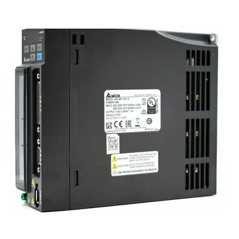
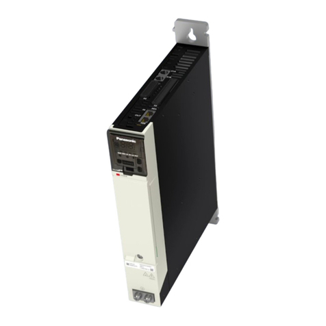
Harmonic Drive HA-680 Series User manual

AC Servo Driver for
24 VDC Power Supply
HA-680 Series Manual
(
For FHA-8C, 11C, 14C/RSF-3C,5B/8B,11B, and 14B
)
●Thank you very much for your purchasing our HA-680 series AC
servo driver for 24 VDC power supply.
●Parameter setting for this servo driver requires dedicated
communication software PSF-520.
(The dedicated communication software can be downloaded from our website at
http://www.hds.co.jp/.)
●Be sure to use sufficient safety measures when installing and
operating the equipment so as to prevent an accident resulting in
a serious physical injury damaged by a malfunction or improper
operation.
●Product specifications are subject to change without notice for
improvement purposes.
●Keep this manual in a convenient location and refer to it
whenever necessary in operating or maintaining the units.
●The end user of the driver should have a copy of this manual.
SOFTWARE Ver.1.0
ISO14001
ISO9001

SAFETY GUIDE
For FHA series, RSF series, HA series
manufactured by Harmonic Drive Systems, Inc
Read this manual thoroughly before designing the application, installation, maintenance or inspection of the actuator.
Indicates a potentially hazardous situation,
which, if not avoided, could result in death
or serious personal injury.
Indicates a potentially hazardous situation, which, if
not avoided, may result in minor or moderate personal
injury and/or damage to the equipment.
LIMITATION OF APPLICATIONS:
The equipment listed in this document may not be used for the applications listed below:
Space equipment
Automobile, automotive parts
Aircraft, aeronautic equipment
Amusement equipment, sport equipment, game machines
Nuclear equipment
Machine or devices acting directly on the human body
Household apparatus
Instruments or devices to transport or carry people
Vacuum equipment
Apparatus or devices used in special environments
If the above list includes your intending application for our products, please consult us.
Safety measures are essential to prevent accidents resulting in death, injury or damage of the equipment due to
malfunction or faulty operation.
CAUTIONS FOR ACTUATORS AT APPLICATION DESIGNING
Always use under followings conditions:
-Ambient temperature: 0°C to 40°C
-Ambient humidity: 20% to 80%RH (Non-condensation)
-Vibration: Max 24.5 m/S2
-No contamination by water, oil
-No corrosive or explosive gas
Follow exactly the instructions in the relating
manuals to install the actuator in the equipment.
-Ensure exact alignment of motor shaft center and
corresponding center in the application.
Failure to observe this caution may lead to vibration,
resulting in damage of output elements.
CAUTION FOR ACTUATORS IN OPERATIONS
Keep limited torques of the actuator.
-Keep limited torques of the actuator.
-Be aware, that if arms attached to output element hits
by accident an solid, the output element may be
uncontrollable.
Never connect cables directly to a power supply
socket.
-Each actuator must be operated with a proper driver.
-Failure to observe this caution may lead to injury, fire or
damage of the actuator.
Do not apply impacts and shocks
-Do not use a hammer during installation
-Failure to observe this caution could damage the
encoder and may cause uncontrollable operation.
Avoid handling of actuators by cables.
-Failure to observe this caution may damage the wiring,
causing uncontrollable or faulty operation.
CAUTIONS FOR DRIVERS AT APPLICATION DESIGNING
Always use drivers under followings conditions:
-Mount in a vertical position keeping sufficient distance
to other devices to let heat generated by the driver
radiate freely.
-Ambient temperature: 0°C to 50°C
-
Ambient humidity: less than 95% RH (Non
condensation)
-No vibration or physical shock
-No contamination by water, oil or foreign matters
-No corrosive, inflammable or explosive gas
Use sufficient noise suppressing means and safe
grounding.
-Keep signal and power leads separated.
-Keep leads as short as possible.
-Ground actuator and driver at one single point, minimum
ground resistance class: D (less than 100 ohms)
-Do not use a power line filter in the motor circuit.
Pay attention to negative torque by inverse load.
–Inverse load may cause damages of drivers.
-Please consult our sales office, if you intent to apply
products for inverse load.
Use a fast-response type ground-fault detector
designed for PWM inverters.
-Do not use a time-delay-type ground-fault detector.
CAUTION FOR DRIVERS IN OPERATIONS
Never change wiring while power is active.
-Make sure of power non-active before servicing the
products.
-Failure to observe this caution may result in electric
shock or personal injury.
Do not touch terminals or inspect products at least
5 minutes after turning OFF power.
-Otherwise residual electric charges may result in electric
shock.
-Make installation of products not easy to touch their inner
electric components.
Do not make a voltage resistance test.
-Failure to observe this caution may result in damage of
the control unit.
-Please consult our sales office, if you intent to make a
voltage resistance test.
Do not operate control units by means of power
ON/OFF switching.
-
Start/stop operation should be performed via input
signals.
Failure to observe this caution may result in deterioration
of electronic parts.
DISPOSAL OF AN ACTUATOR, A MOTOR, A CONTROL UNIT AND/OR THEIR PARTS
All products or parts have to be disposed of as industrial waste.
-Since the case or the box of drivers have a material indication, classify parts and dispose them separately.
CAUTION
CAUTION
CAUTION
WARNING
WARNING
WARNING
CAUTION
WARNING
CAUTION
CAUTION
CAUTION
WARNING
WARNING
CAUTION
CAUTION
CAUTION
CAUTION
SYSTEMS
®

HA-680 series servo driver manual
- Contents 1 -
Contents
Chapter 1 Outlines of HA-680 driver ................................................................... 1
1-1 Main features...............................................................................................................1
1-2 Model of HA-680 driver ............................................................................................... 2
1-3 Combinations with actuators ....................................................................................... 2
1-4 Specifications of HA-680 drivers ................................................................................. 3
1-5 External drawing of the HA-680 drivers ...................................................................... 4
1-6 Names and functions of parts...................................................................................... 5
1-7 Outlines of I/O ports..................................................................................................... 7
1-7-1 TB2: Power supply connection terminal...................................................................... 7
1-7-2 TB1: Actuator connection terminal .............................................................................. 7
1-7-3 CN1: Encoder connector ............................................................................................. 7
1-7-4 CN3: Serial port connector .......................................................................................... 8
1-7-5 CN4: CAN connector................................................................................................... 8
1-8 CN2: Overview of I/O signal ........................................................................................ 9
1-9 LED display ................................................................................................................11
1-10 Outline of protective functions ....................................................................................11
1-11 Protective functions ................................................................................................... 12
Chapter 2 I/O ports ............................................................................................. 15
2-1 Assignment of I/O signals.......................................................................................... 15
2-1-1 Assignment of input signals....................................................................................... 15
2-1-2 Assignment of output signals .................................................................................... 16
2-1-3 Type of I/O signal connector CN2 ............................................................................. 16
2-2 Position control .......................................................................................................... 17
2-2-1 I/O port layout ............................................................................................................ 17
2-2-2 I/O port connections in the position control ............................................................... 18
2-2-3 I/O port functions in the position control .................................................................... 19
2-2-4 Connection examples in the position control............................................................. 27
2-3 Speed control............................................................................................................. 33
2-3-1 Pin numbers and names of I/O signals ..................................................................... 33
2-3-2 I/O port connections in the speed control.................................................................. 34
2-3-3 I/O port functions in the speed control....................................................................... 35
2-3-4 Connection examples in the speed control ............................................................... 43
2-4 Torque control............................................................................................................ 46
2-4-1 Pin numbers and names of I/O signals ..................................................................... 46
2-4-2 I/O port connections in torque control ....................................................................... 47
2-4-3 I/O port functions in torque control ............................................................................ 48
2-4-4 Connection examples in torque control..................................................................... 55

HA-680 series servo driver manual
- Contents 2 -
Chapter 3 Installing HA-680 driver ................................................................... 58
3-1 Receiving Inspection ................................................................................................. 58
3-2 Notices on handling................................................................................................... 59
3-3 Location and installation............................................................................................ 60
3-3-1 Environment of location............................................................................................. 60
3-3-2 Notices on installation................................................................................................ 60
3-3-3 Installing .................................................................................................................... 61
3-4 Suppressing noise..................................................................................................... 61
3-4-1 Devices for grounding ............................................................................................... 61
3-4-2 Installing noise filters ................................................................................................. 62
3-4-3 Instructions for cabling .............................................................................................. 63
3-5 Connecting power cables .......................................................................................... 64
3-5-1 Instructions for power supply..................................................................................... 64
3-5-2 Allowable size of cables ............................................................................................ 64
3-5-3 Connecting power cables .......................................................................................... 65
3-6 Connecting the ground wire ...................................................................................... 66
3-7 Connecting motor and regeneration resistor cables ................................................. 66
3-8 Connecting regenerative absorption resistance / capacitors .................................... 67
3-9 Connecting cables for the encoder and the I/O......................................................... 69
3-9-1 Preparing the encoder cable and the I/ O cable........................................................ 69
3-9-2 Pin layout of encoder connector (CN1) ..................................................................... 69
3-9-3 Pin-layouts of the I/O signal connector (CN2)........................................................... 71
3-9-4 Connecting cables for the encoder and I/O signals .................................................. 72
3-9-5 EIA-232C (RS-232C) cable specifications ................................................................ 72
3-10 Power ON and OFF sequences ................................................................................ 73
3-10-1 Power ON / OFF sequence circuit............................................................................. 73
3-10-2 Frequency of power ON / OFF operation.................................................................. 73
3-10-3 Power on and off sequences..................................................................................... 73
Chapter4 Functions of dedicated communication software PSF-520........... 74
Chapter5 Operations ......................................................................................... 75
5-1 Trial run...................................................................................................................... 75
5-1-1 Driving actuator only.................................................................................................. 75
5-1-2 Setting parameters .................................................................................................... 77
5-1-3 End of trial run ........................................................................................................... 77
5-2 Normal operation ....................................................................................................... 78
5-2-1 Notices for daily operations ....................................................................................... 78
5-2-2 Daily maintenance ..................................................................................................... 78
Chapter 6 Setting up parameters ..................................................................... 79
6-1 Parameter list ............................................................................................................ 79
6-2 Function of the parameters ....................................................................................... 80
6-3 Default parameter list .............................................................................................. 101

HA-680 series servo driver manual
- Contents 3 -
Chapter 7 Troubleshooting .............................................................................. 109
7-1 Alarms and diagnostic tips ...................................................................................... 109
7-2 Troubleshooting for improper actuator motions....................................................... 121
7-2-1 Improper motions in position control ....................................................................... 121
7-2-2 Improper motions in speed and torque control........................................................ 125
Chapter 8 Options ........................................................................................... 129
8-1 Relay cables ............................................................................................................ 129
8-2 Connectors .............................................................................................................. 130
8-3 Dedicated communication software RSF-520 (free) ............................................... 130

HA-680 series servo driver manual
MEMO

Chapter 1 Outlines of the HA-680 driver
- 1-
Chapter 1 Outlines of HA-680 driver
The HA-680 driver for 24 VDC power supply is a dedicated driver designed to drive: the ultra-thin/hollow
shaft structure 24-VAC actuator FHA-C mini combining a ultra-thin/speed reducer HarmonicDrive®for
precision control and flat AC servo motor; the ultra-small AC Servo Actuator RSF supermini series
combining an ultra-small HarmonicDrive®and ultra-small AC servo motor; and the RSF-B mini series.
The HA-680 drivers provide many superior functions to allow the 24-VAC FHA-C mini type, RSF
supermini series, and RSF-B series to excel in performance.
1-1 Main features
◆Small and compact design
It is about half the size of a postcard, just the size of a card case. Its ultra-light design with a weight of
230 g is useful for small, space-saving devices.
◆Substantial functions
Position control, speed control, and torque control are provided as standard. It is compact and has
substantial functions at the same time.
◆Easy function setting
Parameters can be set easily using dedicated communication software PSF-520.
◆Wide range of operation state display
I/O signals, rotation speed, and deviation can be monitored using dedicated communication software
PSF-520.
Up to eight previous alarms are also indicated as alarm history that is helpful for diagnosis.
◆The main circuit power supply and the control power supply are separated.
Because the main circuit power supply and the control power supply are separated, safe diagnosis can
be performed in case of failure.
◆Easy test run adjustment
Adjustment can be performed using dedicated communication software PSF-520.
◆Electronic gear suitable for mechanical system
The electronic gear function adjusts commands to a feed pitch of a driven mechanism such as gears or
lead screws.
◆Three types of input signals for position commands
Three types of input signals for the position command are selectable: two-pulse train, single-pulse train,
and two-phase pulse train.
◆Regenerative circuit provided as standard
It incorporates a regenerative circuit as standard. You can use it in applications with a large moment of
inertia without worrying about regeneration.

Chapter 1 Outlines of the HA-680 driver
- 2-
1-2 Model of HA-680 driver
Model and sign of HA-680 driver are described as follows:
Note that the model varies depending on the actuator used.
◆HA-680 driver:
Optional
Extension cables: For FHA-Cmini 24VAC type (optional)
for HA-680
for a motor EWC - MB * * -A06 – TN2
for an encoder EWC - E * * -M06 - 3M14
for EIA-232C
HDM-RS232C (cable length: 1.5m)
* * means cable length: 03: 3m, 05: 5m, 10: 10m (three kinds of length are available.)
Extension cables: For RSF supermini series (optional)
(Require for connecting actuator and driver)
for HA-680
for a motor
EWA - M* * -JST04 – TN2
for an encoder
EWA - E * * -JST09 - 3M14
for EIA-232C
HDM-RS232C (cable length: 1.5m)
* * means cable length: 03: 3m, 05: 5m, 10: 10m (three kinds of length are available.)
Extension cables: For RSF-B mini series (optional)
(Require for connecting actuator and driver)
for HA-680
for a motor
EWC - MB* * -A06 – TN2
for an encoder + pole sensor
EWB - F * * -M0809 - 3M14
for EIA-232C HDM-RS232C (cable length: 1.5m)
* * means cable length: 03: 3m, 05: 5m, 10: 10m (three kinds of length are available.)
Connectors (optional): CNK-HA68-S1 / CNK-HA68-S2
Dedicated communication software (provided free of charge): PSF-520
Parameter setting and change can be performed using dedicated communication software PSF-520.
Dedicated communication software PSF-520 can be downloaded from our website at http://www.
hds.co.jp/.
If you do not have an environment to download it from the Internet, please ask one of our branch offices.
HA-680-4 □-200
AC servo driver
680 series
Nominal current
Input voltage
Corresponding
sign
4
4A
6
6A
None
For FHA-Cmini 24VAC type (FHA-8C,11C,14C)
B
For RSF supermini series (RSF-3C,5B)
For RSF-B series (RSF-8B,11B,14B)
24
24VDC

Chapter 1 Outlines of the HA-680 driver
- 3-
1-3 Combinations with actuators
Five HA-680 models are available for use with actuators dealing with their nominal current and encoder
systems. The correct combinations are as follows:
Model
HA-680-4-24 HA-680-6-24 HA-680-4B-24 HA-680-6B-24
Actuator model FHA-8C
FHA-11C FHA-14C
RSF-3C
RSF-5B
RSF-8B
RSF-11B
RSF-14B
1-4 Specifications of HA-680 drivers
Driver model
Item
HA-680-4-24
HA-680-6-24
HA-680-4B-24 HA-680-6B-24
Combined actuator FHA-8C FHA-11C FHA-14C RSF-3C RSF-5B RSF-8B RSF-11B RSF-14B
Allowable continuous
current (Arms)
note
2
1.8 3.9 6.0 0.7 1.2 2.0 5.0 4.9
Instantaneous max.
current (Arms)
note
3
3.4 8.4 16.5 1.5 2.3 3.9 15.8 17.2
Supply
voltage
Control circuit
power supply (CP)
DC24V(20~28V)
Main circuit power
supply (MP)
DC24V(20~28V)
Control method
Sinusoidal PWM control
switching frequency 12.5kHz
Encoder 4-line specification, serial transmission
method, line driver input
14-line specification
Line driver input
8-line specification
Line driver input
Pole sensor
8-line specification
Line driver input
I/O signal DI: 5 points (insulation with phto coupler) DO: 5 points (insulation with phto coupler)
Variable function assignment
Encoder monitor
Phase-A,B,Z line driver output Phase-Z open collector output (insulation with phto coupler)
Control mode
Speed, position and torque control
Display LED 2 points (green:1 point red:1 point)For power on, servo-on, alarm operation state display
Speed
control
Command voltage
DC0V~
±
10V/maxium speed
Input signal
FWD-enable, REV-enable, Alarm clear, Speed Command internal/external switch, Speed limiting, Current
limiting
Output signal
Attained speed, Alarm, ready, limiting speed, limiting current, Phase-Z open collector output
Speed control range
1:1000 or more
Position
control
Command pulse
interface Line driver: 500kp/s(max) open collector: 200kp/s(max)
Command
configuration
2- pulse (FWD/REV pulse train), 1 pulse method (sign+pulse train),
2-phase pulse method (90-degree phase difference 2-phase pulse train)
Input signal
FWD-inhibit, REV-inhibit, clear, Deviation clear, Speed limiting, Current limiting
Output signal
In-position, alarm, ready, limiting speed, limiting current, Phase-Z open collector output
Torque
control
Command voltage DC0V~±10V/Max. torque
Input signal FDW rotation start, REV rotation start, alarm clear, torque command internal/external switch, current limit
Output signal Attained speed, alarm, operation ready, limiting current, Phase-Z open collector output
Protection function
Overload, Max. deviation, Encoder break detection, encoder reception error, UVW error, regenerative error,
operating temperature error, system error, overcurrent, load short circuit, memory error, overspeed
Connector
I/O: 3M half-pitch 26-pin
encoder: 3M half-pitch 14-pin
RS-232C: Small-type 8-pin
CAN: RJ type
Regenerative absorption circuit
Incorporated (with an external capacitor/resistor installation terminal). The built-in resistance has a fuse.
Structure
Semi-covered type (aluminum base with plastic cover)
Installation method
Base mount (wall installation)
Mass
230g
Ambient conditions
Operating temp:0~50°CStorage temp:-20~85°C
Operating humidity/storage humidity:95%RH or less (no condensation)
No vibration or physical shock.
No powder dust, metal powder, corrosive gas, flammable gas, or oil mist.
No water or oil splashed.
To be used indoors. No direct sunlight.
Note 1: Parameter setting of this driver is performed depending on the actuator combined with it. It cannot be used
for any other actuator.
Note 2: This value may be limited depending on the combined actuator.

Chapter 1 Outlines of the HA-680 driver
- 4-
1-5 External drawing of the HA-680 drivers
The HA-680 driver model indication and the mark shown in this manual are as follows:
Unit: mm
When HA-680 drivers are installed in a cabinet, leave enough ventilation space for cooling as shown
below.
Air
Air
Control cabinet
Cooling fan
Wall mount
30mm or more
30mm or more
30mm
or more
50mm or
more
50mm or
more
Driver
Air
Air filter
Air
Cover
Ground mark
Specification indication plate
Software version No. seal
2-washer cross pan-head machine screw
(brass round) M3x6
Heat sink
Regenerative resistance
internal/external switch terminal

Chapter 1 Outlines of the HA-680 driver
- 5-
1-6 Names and functions of parts
LED display unit
Displays the operation state of the HA-680 driver with the green and red LEDs.
TB2: Power supply connection terminals
The terminals for power supply. These are divided into terminals for the control circuit power supply and
terminals for the main circuit power supply.
TB1: Actuator/external regenerative resistance connection terminal
The lead line of the actuator and an external regenerative resistance are connected here.
CN1: Encoder connector
The position detection encoder cable of the actuator is connected here.
CN2: Control I/O connector
This connector is for receiving control signals from the host controller.
•CN5: Not available (on the side)
•CN4: CAN connector
•CN3: EIA-232C serial
port connector
•CAN terminal resistance
switch jumper
•TB2: Power supply
connection terminal
•LED display
•Ground connection
terminal
•CN2: Control I/O
connector
•CN1: Encoder connector
•TB1: Actuator/external
regenerative resistance
connection terminal
•Regenerative resistance
switch jumper (on the side)

Chapter 1 Outlines of the HA-680 driver
- 6-
CN3: Serial port connector
The connector for connection with a PC. This is used for monitoring the output current and setting
parameters.
Connection with a PC requires dedicated communication cable “HDM-RS232C.”Parameter setting
requires dedicated communication software PSF-520.
CN4: CAN connector
Connector for CAN communication.
Note: Currently not available. For details, contact one of our branch offices.
CN5: Not available
This connector is for manufacture only. The customer should never use it.
Ground connection terminal
This terminal is for grounding. Connect the ground (earth) line here to prevent electric shock.
CAN terminal resistance switch jumper
Enables or disables the terminal resistance for CAN.
Note: Currently, the CAN function is not installed. Therefore, setting this jumper is meaningless.
Regenerative resistance switch jumper
Switches between the internal regenerative resistance and the external regenerative resistance.
Installing the jumper between the center pin and left pin selects the internal regenerative resistance, and
installing the jumper between the center pin and right pin selects the external regenerative resistance.
For details, refer to 3-8 Connecting regenerative absorption resistances/capacitors.

Chapter 1 Outlines of the HA-680 driver
- 7-
1-7 Outlines of I/O ports
1-7-1 TB2: Power supply connection terminal
Pin No.
Signal name
Description
1
CP+
Control circuit power supply + (DC+24V)
For details, refer to 3-5.
2
CP-
Control circuit power supply −(0V)
3
MP+
Main circuit power supply + (DC+24V)
4
MP-
Main circuit power supply −(0V)
5
NC
Do not connect
1-7-2 TB1: Actuator connection terminal
Pin No.
Signal name
Description
1
VM
External capacitor connection terminal
For details, refer to 3-8.2 R External regenerative resistance connection terminal
3
GND
External capacitor/regenerative resistance connection terminal
4
U
Actuator U-side connection terminal
For details, refer to 3-7.5 V Actuator V-side connection terminal
6
W
Actuator W-side connection terminal
1-7-3(1) CN1: Encoder connector (For FHA-Cmini 24VAC-type actuators)
Pin No.
Signal name
Description
1 Vcc
The power is supplied from the inside of the servo amplifier with the +5 V power
supplied to the encoder.
2
NC Do not connect.
3
4
5
SD+
Input terminal for the encoder data input signal from the actuator
6 NC Do not connect.
7
SD-
Input terminal for the encoder data input signal from the actuator
8
GND
Common terminal of the +5 V power supplied to the encoder
9
NC Do not connect.
10
11
12
13
14
(2) CN1: Encoder connector (For RSF supermini series actuators)
Pin No.
Signal name
Description
1 Vcc The power is supplied from the inside of the servo amplifier with the +5 V power
supplied to the encoder.
2 B+ Phase-B signal input+(LD)
3
Z+
Phase-Z signal input +(LD)
4
B-
Phase-B signal input -(LD)
5 A+ Phase-A signal input +(LD)
6
Z-
Phase-Z signal input -(LD)
7
A-
Phase-A signal input +(LD)
8
GND
Common terminal of the +5 V power supplied to the encoder
9
U+
Phase-A signal input +(LD)
10
U-
Phase-Z signal input -(LD)
11
V+
Phase-A signal input +(LD)
12 V- Phase-B signal input -(LD)
13
W+
Phase-A signal input +(LD)
14
W-
Phase-Z signal input -(LD)
Note 1: LD indicates the line driver.

Chapter 1 Outlines of the HA-680 driver
- 8-
(3) CN1: Encoder connector (For RSF-B mini series actuators)
Pin No.
Signal name
Description
1 Vcc
The +5V power supply to the encoder and pole sensor is used to supply power
from inside the servo amplifier.
2
B+
Phase-B signal input+(LD)
3 Z+ Phase-Z signal input +(LD)
4
B-
Phase-B signal input -(LD)
5
A+
Phase-A signal input +(LD)
6 Z- Phase-Z signal input -(LD)
7
A-
Phase-A signal input +(LD)
8 GND
This is a common terminal of the +5V power supply to the
encoder and pole sensor.
9 U+ Phase-A signal input +(LD)
10
U-
Phase-Z signal input -(LD)
11
V+
Phase-A signal input +(LD)
12 V- Phase-B signal input -(LD)
13
W+
Phase-A signal input +(LD)
14
W-
Phase-Z signal input -(LD)
1-7-4 CN3: Serial port connector
Pin No.
Signal name
Description
1 FG Frame ground
2
RXD
Transmission data
3
TXD
Reception data
4
DTR
Data terminal ready
5
GND
Signal ground
6
DSR
Data set ready
7
NC
Do not connect.
8
NC
Do not connect.
(Dedicated communication cable “HDM-RS232C” is required.)
1-7-5 CN4: CAN connector
Pin No.
Signal name
Description
1
CANH
CAN-High signal
2
CANL
CAN-Low signal
3
NC
Do not connect.
4 NC Do not connect.
5
NC
Do not connect.
6
NC
Do not connect.
7
NC
Do not connect.
8
NC
Do not connect.
Note: Currently not available.

Chapter 1 Outlines of the HA-680 driver
- 9-
1-8 CN2: Overview of I/O signal
The CN2 connector performs input and output of control signals with the host control device. The
connector has 26 pins, which are assigned for “position control,” “speed control,” and “torque control” as
shown in the table below.
Position control
Speed control
Pin
No.
Signal Symbol I/O
Pin
No.
Signal Symbol I/O
1 Output 1 (in-position ready) IN-POS Output 1
Output 1(Attained speed
Output)
HI-SPD Output
2
Output 2(Alarm Output)
ALARM
Output
2
Output 2 (Alarm Output)
ALARM
Output
3 Output 3 ―Output 3 Output 3 ―Output
4 Output 4 ―Output 4 Output 4 ―Output
5 Output 5 (Phase-Z OC
Output)
Z Output 5 Output 5 (Phase-Z OC
Output)
Z Output
6
Output signal common
OUT-COM
Output
6
Output signal common
OUT-COM
Output
7
Input 1 (Servo-ON)
S-ON
Input
7
Input 1 (Servo-ON)
S-ON
Input
8
Input 2
―
Input
8
Input 2 (FWD start)
FWD-EN
Input
9
Input 3
―
Input
9
Input 3 (REV start)
REV-EN
Input
10 Input 4 ―Input 10 Input 4 ―Input
11 Input 5 ―Input 11 Input 5 ―Input
12
Input signal common
IN-COM
Input
12
Input signal common
IN-COM
Input
13
Encoder monitor GND
MON-GND
Output
13
Encoder monitor GND
MON-GND
Input
14
FWD pulse +
FWD+
Input
14
―――
15
FWD pulse -
FWD-
Input
15
―
―
―
16 REV pulse + REV+ Input 16 ―――
17 REV pulse - REV- Input 17 ―――
18 +24v +24v Input 18 ―――
19 ―――19 Speed command SPD-CMD Input
20
―
―
―
20
Speed command ground
SPD-GND
Input
21
Phase-A Output + (LD)
A+
Output
21
Phase-A Output + (LD)
A+
Output
22
Phase-A Output - (LD)
A-
Output
22
Phase-A Output - (LD)
A-
Output
23 Phase-B Output + (LD) B+ Output 23 Phase-B Output + (LD) B+ Output
24
Phase-B Output - (LD)
B-
Output
24
Phase-B Output - (LD)
B-
Output
25
Phase-Z Output + (LD)
Z+
Output
25
Phase-Z Output + (LD)
Z+
Output
26 Phase-Z Output - (LD) Z- Output 26 Phase-Z Output - (LD) Z- Output
Note 1: OC indicates the open collector. LD indicates the line driver.
Note 2: For terminals without a signal name for input and output, function assignment can be changed in
parameter setting. For details, refer to 2-1.
Do not connect the pins with “-” in the Signal column to the external
device.
If you do, failure may occur because it is connected to the internal circuit.
CAUTION

Chapter 1 Outlines of the HA-680 driver
- 10 -
Torque control
Pin No.
Signal
Symbol
I/O
1
Output 1 (Attained speed)
HI-SPD
Output
2 Output 2 (Alarm) ALARM Output
3
Output 3 (operation ready)
READY
Output
4
Output 4 (limiting current)
CUR-LMT-M
Output
5 Output 5 (Phase-Z Output OC) Z Output
6
Output signal common
OUT-COM
Output
7
Input 1(Servo-ON)
S-ON
Input
8 Input 2 (FWD start) FWD-EN Input
9
Input 3 (REV start)
REV-EN
Input
10 Input 4 ―
Input
11 Input 5 ―
Input
12
Input signal common
IN-COM
Input
13 Encoder monitor GND MON-GND Output
14 ―――
15
―
―
―
16 ―
―
―
17 ―
―
―
18
―――
19
Torque command
TRQ-CMD
Input
20 Torque command ground TRQ-GND Input
21
Phase-A Output + (LD)
A+
Output
22
Phase-A Output - (LD)
A-
Output
23 Phase-B Output + (LD) B+ Output
24
Phase-B Output - (LD)
B-
Output
25
Phase-Z Output + (LD)
Z+
Output
26
Phase-Z Output - (LD)
Z-
Output
Note 1: OC indicates the open collector. LD indicates the line driver.
Note 2: For Input 4 and Input 5, function assignment can be changed in parameter setting. For details,
refer to 2-1.
Do not connect the pins with “-” in the Signal column to the external
device.
If you do, failure may occur because it is connected to the internal circuit.
CAUTION

Chapter 1 Outlines of the HA-680 driver
- 11 -
1-9 LED display
The 2 LEDs (green and red) indicate the state of the HA-680 driver.
State
LED green
LED red
Remarks
Control power ON
ON
OFF
The connected actuator and the actuator set to
the driver are different.
Blinking OFF
Servo-ON
ON
ON
Alarm (*1) ON Blinking
The number of times it blinks varies
depending on the alarm. Refer to 1-10.
CPU error
Blinking
Blinking
The green and red LEDs blink alternately.
*1 If two or more alarms occur, only the latest alarm is displayed.
1-10 Outline of protective functions
The HA-680 driver has various types of protection function. When an error occurs in the system, it
immediately turns off the servo, and outputs an “alarm” signal to the host device.
When these protection functions trip, driving of the actuator is stopped (the motor becomes servo-off),
and the display LED blinks at 0.5-second intervals. (It illuminates in green and blinks in red: The number
of times it blinks varies depending on the alarm. See below.)
If two or more alarms occur, only the latest alarm is displayed. Up to 8 latest alarms are recorded.
Recorded alarms can be checked with “Alarm History” of dedicated communication software PSF-520.
Alarm code Description No. of times
LED blinks Releasing
Overload Electronic thermal detected an overload state. 1 Available *1
Deviation counter
overflow
The value of the deviation counter exceeded the parameter
setting value.
2 Available *1
Encoder break
detection
The encoder line was broken. 3 Not available *2
Encoder reception
error
Serial encoder data could not be received 10 times in a row. 4
Not available *2
Serial encoder data could not be received over an extended time
period, and encoder monitor could not be outputted successfully.
5
UVW error All UVW signals of the encoder became the same level. 6 Not available *2
Regenerative error The main circuit voltage detection circuit detected overvoltage. 7 Not available *2
Operation
temperature error
The temperature of the HA-680 main unit tripped the temperature
rise sensor.
8 Not available *2
System error An error of the current detection circuit was detected. 9 Not available *2
Overcurrent The current detection circuit detected excessive current. 10 Not available *2
Load short circuit Excessive current flowed through the FET. 11 Not available *2
Memory error Read/write of EEPROM failed. 12 Not available *2
Overspeed The motor axis speed exceeded the maximum rotation speed
+100 rpm for 0.5 s or longer. 13 Not available *2
*1 The servo does not turn on unless the S-ON signal is entered again after the alarm is cleared with the
CLR signal.
*2: Shut off the power supply after remedying a cause of the alarm that releasing is impossible. Then
turn on the power supply.

Chapter 1 Outlines of the HA-680 driver
- 12 -
The following example illustrates how the LED blinks in case of an alarm.
0.5s 0.5s 0.5s 2s 0.5s 0.5 s 0.5s
In the above example, the LED blinks 4 times at 0.5-s intervals, which indicates an “encoder reception
error.”
1-11 Protective functions
HA-680 drivers provide the following protective functions and show the alarm displays on 1-10.
◆Overload
The driver always monitors the motor current, and if the current exceeds the curve in the figure below,
the overload alarm occurs. Occurrence of the overload alarm varies depending on the actuator.
FHA-C mini AC24V type
(1)
The alarm occurs when a current of more than
1.25 times the allowable continuous current of
the actuator flows for about 170 seconds.
(2)
The alarm occurs when a current of 3 times the
allowable continuous current of the actuator
flows for about 16 seconds.
RSF supermini series (RSF-5B)
(1) The alarm occurs when a current of more than
1.2 times the allowable continuous current of
the actuator flows for about 35(45) seconds.
(2)
The alarm occurs when a current of 2 times the
allowable continuous current of the actuator
flows for about 5(6) seconds.
HA-680過負荷アラーム検出時間
0
5
10
15
20
25
30
35
40
45
50
50 100 150 200 250 300
出力トルク[%}
検出時間[s]
RSF-3C
RSF-5B
Detection time [s]
Output torque [%] The rated torque is 100%.
RSF supermini series
Overload alarm occurrence time
( )The inside is RSF-3C
0
20
40
60
80
100
120
140
160
180
200
0 50 100 150 200 250 300
出力トルク [%] 定格を100%とする
検出時間 [s]
Output torque [%] The rated torque is 100%.
Detection time [s]
FHA-C mini AC24V type

Chapter 1 Outlines of the HA-680 driver
- 13 -
RSF-11B
(1)
The alarm occurs when a current of more than
1.2 times the allowable continuous current of the
actuator flows for about 23 seconds.
(2)
The alarm occurs when a current of 1.5 times
the allowable continuous current of the actuator
flows for about 10 seconds.
It is possible to clear the alarm by inputting ON signal to [CN2 Clear or Alarm clear] if it is not overload,
again.
◆Deviation counter overflow
The alarm occurs when the value of the deviation counter exceeds the parameter setting value
(PSF-520 No.21 Allowable position deviation). This alarm can be reset by inputting an ON signal to
“CN2 Alarm Clear: ALM-CLR” after inputting an ON signal to “CN2 Clear: CLEAR” or “CN2 Deviation
Clear: DEV-CLR.”
◆Encoder break detection
This alarm occurs when the signal from the encoder is lost. To reset the alarm, you must shut down the
power and turn it on again after diagnosing the cause.
◆Encoder reception error
This alarm occurs when data cannot be received from the encoder successfully, or encoder signal output
cannot be performed.
◆UVW error
An alarm occurs if encoder or pole sensor phase UVW signals become abnormal. To reset the alarm,
you must shut down the power and turn it on again after diagnosing the cause.
To clear the alarm after troubleshooting, shut off the control power once and turn it on again.
RSF-8B
(1) The alarm occurs when a current of more than
1.2 times the allowable continuous current of the
actuator flows for about 13 seconds.
(2) The alarm occurs when a current of 1.5 times
the allowable continuous current of the actuator
flows for about 6 seconds.
RSF-14B
(1)
The alarm occurs when a current of more than
1.2 times the allowable continuous current of the
actuator flows for about 45 seconds.
(2)
The alarm occurs when a current of 2.5 times
the allowable continuous current of the actuator
flows for about 5 seconds.
RSF シリーズ
0
5
10
15
20
25
30
35
40
45
50
50 100 150 200 250 300
出力トルク [%]
検出時間 [s]
RSF-14B
RSF-8B
RSF-11B
RSF-B mini series
Detection time [s]
Output torque [%] The rated torque is 100%.

Chapter 1 Outlines of the HA-680 driver
- 14 -
◆Regenerative error
The alarm occurs when the voltage of the main circuit exceeds 50 V. If the moment of inertia of the load
is large, the main circuit voltage increases due to the energy generated during deceleration of the
actuator.
The regenerative resistance of the regenerative absorption circuit incorporates a fuse. When the
temperature of the regenerative resistance increases due to excessive regeneration and the fuse is
blown, the regenerative circuit no longer works, and the main circuit voltage increases. If the
regenerative error occurs immediately the control circuit power is shut down and turned on again, it may
be due to a blown fuse. In this case, connect the external regenerative resistance and switch the jumper
setting.
For connection of an external regenerative resistance and change of the jumper setting, refer to 3-8.
◆Operating temperature error
The alarm occurs when the temperature of the HA-680 main unit increases and the temperature sensor
trips. To reset the alarm, you must shut down the power and turn it on again after diagnosing the cause.
◆System error
This alarm occurs when an error of the motor current detection circuit is detected. To reset the alarm,
you must shut down the power and turn it on again after diagnosing the cause.
◆Overcurrent
This alarm occurs when overcurrent is detected by the motor current detection circuit. To reset the alarm,
you must shut down the power and turn it on again after diagnosing the cause.
◆Load short circuit
The alarm occurs when excessive current flows through the FET. To reset the alarm, you must shut
down the power and turn it on again after diagnosing the cause.
◆Memory error
The alarm occurs when read/write fails due to failure of the EEPROM memory of the driver. It can be
reset by shutting down the power and turning it on again. However, if the same phenomenon persists, it
may be due to failure. Contact one of our branch offices.
◆Overspeed
The alarm occurs when the rotation speed of the actuator exceeds the motor axis maximum rotation
speed +100 rpm for 0.5 s or longer. To clear the alarm, shut off the control power once and turn it on
again.
This manual suits for next models
4
Table of contents
Other Harmonic Drive Servo Drive manuals

Harmonic Drive
Harmonic Drive LAH Series User manual
Harmonic Drive
Harmonic Drive HA-675 Series User manual
Harmonic Drive
Harmonic Drive HMA Series User manual
Harmonic Drive
Harmonic Drive HS-360 Series User manual
Harmonic Drive
Harmonic Drive H A - 800A User manual

Harmonic Drive
Harmonic Drive HA-520 Series User manual
Popular Servo Drive manuals by other brands
Technosoft
Technosoft Micro 4803 SX Technical reference
Emerson
Emerson TRINORM 436 Series instruction manual
Omron
Omron R88M-K Series user manual
Inovance
Inovance SV660N Series Advanced user's guide
Xinje
Xinje DS3 series servo user manual
Danfoss
Danfoss VLT 6002-6011 Installation, operation and maintenance manual
