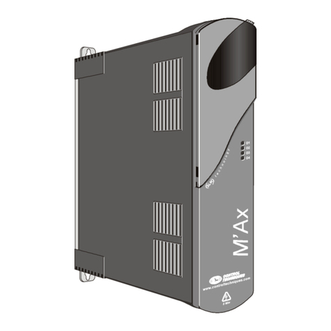
Electro-Craft BRU-200 User manual

BRU-200
and
BRU-500
Brushless
Drives
Instruction
Manual
Electro-Craft®
Servo
Products

Electro-Craft
BRU-200
and
BRU-500
Brushless
Drives
Instruction
Manual
P/N
0013-1028-001
Revision
B
Reliance
Motion
Control,
Inc.
6950
Washington
Avenue
South
Eden
Prairie,
MN
55344
612-942-3600
Technical
Support:
800-328-3983

ONLY
QUALIFIFED
ELECTRICAL
PERSONNEL
FAMILIAR
WITH
THE
CONSTRUCTION
AND
OPERATION
OF
THIS
EQUIPMENT
AND
THE
HAZARDS
INVOLVED
SHOULD
INSTALL,
ADJUST,
OPERATE
OR
SERVICE
THIS
EQUIPMENT.
READ
AND
UNDERSTAND
THIS
MANUAL
AND
OTHER
APPLICABLE
MANUALS
IN
THEIR
ENTIRETY
BEFORE
PROCEEDING.
FAILURE
TO
OBSERVE
THIS
PRECAUTION
COULD
RESULT
IN
SEVERE
BODILY
INJURY
OR
LOSS
OF
LIFE.
WARNING
THE
USER
MUST
PROVIDE
AN
EXTERNAL,
HARDWIRED
EMERGENCY
STOP
CIRCUIT
OUTSIDE
THE
CONTROLLER
CIRCUITRY.
THIS
CIRCUIT
MUST
DISABLE
THE
SYSTEM
IN
CASE
OF
IMPROPER
OPERATION.
UNCONTROLLED
MACHINE
OPERATION
MAY
RESULT
IF
THIS
PROCEDURE
IS
NOT
FOLLOWED.
FAILURE
TO
OBSERVE
THIS
PRECAUTION
COULD
RESULT
IN
SEVERE
BODILY
INJURY.
Copyright
©
Reliance
Motion
Control,
Inc.
1995.
All
mghts
reserved.
The
information
contained
in
this
manual
is
subject
to
change
without
notice.
Electro-Craft
is
a
registered
trademark
of
Reliance
Electric
Company
or
its
subsidianes.
Tandy
is
a
registered
trademark
of
Tandy
Corporation.
IBM
is
a
registered
trademark
of
Intemational
Business
Machines
Corporation.
INTEL
is
a
trademark
of
Intel
Corporation,
AMP
is
a
trademark
of
AMP
Incorporated.
Molex
is
a
registered
trademark
of
Molex
Incorporated.

Table
of
Contents
TABLE
OF
CONTENTS
SECTION
|
-
INTRODUCTION
V7
PUPPOSC
oo
eee
eceeeee
nee
n
ee
nnetee
pee
ceeeseceuevee
HnMAcHensHenRO
Hea
Enea
LdCAnSOnNAcucaNSA
Ene
LOE
CCEA
CnEOH
SHEE
CnEEH
ALU
DRREEAAAESReud
HE
SEDREREE
EEO
EA RE
1.2
Product
Description...
.
sea
eee
tease
teeeeceecavceneancoeennepeseenneee
vet
ne
set
sagee
peta
nseates
ene
1.2.1
Power
Supply
Modules
(BRU-
500
Only)...
dacneeeseveceescaecenecsessesnesetnsanenersnatengesaneseesutssntenteesnnees
&
1.2.2
Drive
Modules...
ccc
ccccercseceescueesareeseceseecescaeeseeseeesseserensesecoegse
seadsguaggessansaasasapeamasensaeasebenenenens
1.2.3
Motors
amid
Encoders.i....cccccccsscecesetcesecececeaseseseceecasascecnsseseecsecsenssnnaensenecauaneeassrepenenésedeeseestaseoeese
se
1.2.4
Transformers
...
pence
ceneaeacceneneag
cae
cncetsaeseenetinereesenseereaerbeddeaeseseabieeasaaneees
1.2.5
Auxiliary
Power
‘Supply
(BRU-
500
Only)...
enue
sus
cesuassesesceneasseseeccsscecaesatansesaesssaessetuaseaeeseceasvansstesenacates
3
SECTION
II
-
SPECIFICATIONS
2.1
Drive
Module
Specifications
«oes
cc
cececcneeeceeeeeeseoceseecaesoeneseneneeeetersecrereceesecess
or
ttsaviseeameaqsseneeaseneansees
2.2
Power
Supply
Module
Specifications
(BRU-500
Only)...
cece
cee
ccee
cee
nesee
rece
enesvanseerenasinaeesenererersnenas
Dl
2.3
S-Series
Motor
Specifications
TTENV)
.......c:ccecssescesssssseeesessesseesesessseeseessceseseecsevasseeeeecavavisasersasrensertacesissese
O
2.4
F-Series
Motor
Specifications
(TENV)........cccsscsceccscsssnecnensestsscecnesecescensavsveceesseseecscoesnsnetecesstsatpensetsncesnnee
B
25
I-Series
Motor
Specifications
(BRU-5SO0
Only)...
ccsccesssssssssesecesssseesessesescessseseeesecueenteenesceereerseecenesceneneaees
7
2.6
Encoder
Specifications
............cccscceccccecssseescscsnesnesseestesesscenensessecsceascnesscenseseeessenecaessenenenssueqeeteteratencesiyeateneees
2.7
Transformer
Spechications.......0.1..ccccsccecccsessscscssesescsesenesssenensusasevenesseeenscoatvaceusausaaceusersteteseenseseeterecgeeenes
B
2.8
Maximum
Power
LOSS@S.
...........ccccccccccsce
ses
ceeeececeesceee
veseeceesessaeescaseserseeecseseseeessescencevesereerseeseeciesessnasevsanes
SECTION
Ill
-
INSTALLATION
3.1
Mounting
the
Power
Supply
and
Drive
Modules
«...........-.-c-cceseesecseeecceeesusceneaaeeseeenseeeceesenaeeesaecavaeceenseaeers
10
3.2
Power
Wiring...
venue
ceeenneeeseneneeeasinesecursapeeeesessgneeudegeegseqcennsessseesenseseeenetassctsaemesesnesanernte
TO
3.2.1
BRU
500
‘Power
Wiring...
cece
seecaneeesoueeeusesenceneseecassneccenepeesaaeesssscesenstessieseneveertestsamenteraseaneenees
TQ)
3.2.2
BRU-200
Power
Wiring....
besos
ta
caeeeeasesessacesnecae
sua
tasccnerensageeseeeceseeensenstsntennencsstereteriesacre
TT
3.3
Motor
Mounting
amd
Wiritig
nce.
csccsceesesssecesecececeecsesesesessesceseaesesesaeceneseseececesceeceeceseaceererscaeavasenetes
11
3.4
External
Shunt
Mounting
and
Wiring
(BRU-200
DM-30
Option
Only)
0.0...
ccccececeseetetetecsteeeseessenetane
TY
BRU-200/8RU-500
Brushless
Drives
instruction
Manual
iii

Table
of
Contents
SECTION
WV
-
INTERFACE
CIRCUITRY
4.1
Drive
Module
interface
Commectors........ccc
ccc
ee
ccceeecececoessasesseussucueceeessunnsesgueseeserecssgenneenrasesansnerecevens
4.2
Drive
Module
Interface
Signal
SpecifiCations
...........ccccccecccccsceeceeeceeecesuceseneecsuceenrceesaseeneees
4.3
Power
Supply
Module
interlace
Connector
(BRU-S00
Only)...
eeeccsee
teens
sssseencesseeeennarieerereaeeeee
rane
4.4
Power
Supply
Module
Interface
Signal
Specifications
(BRU-500
Only)
oo...
ee
cieceecrcsesereanseenssseeeensees
SECTION
V
-
START-UP
AND
ADJUSTMENTS
5.1
Initial
Start-Up
Procedure
...
§.1.1
Initial
Start-Up
Procedure
(BRU-
500)
...
5.1.2
Initial
Start-Up
Procedure
(BRU-200)
...
5.2
AGIUSTMONNS.
0.
eee
eetetec
eee
cneensareneeneseeenercnsonessseatanessusanaseenseessnecaneeetanenersseseasencesseesensenseeeeeeneeeesmaesareaaeaetaee
5.2.1
Power
Supply
Module
Adjustments
(BRU-500
Only)
oo...
ceceeeeeeseseeseseneesereseceersarteceanetaeararies
5.2.2
Drive
Module
Adjust
ments........---:cscsssrscsserssetavensenesessesseneseeesocecesaeedee
seeaeceeseceeaeees
see
caeeaneesenenates
5.2.3
Serial
Interface
Operation...
seaepeteesnevenaseanseaae
seeseeesescerasnaeceestveasaetseaesereaaeesseeeseeesereee
5.2.3.1
User
Terminal
Requirements
...
qevansuasaecesensesee
cssecenetacsusersucssatersscseeecesstecsevenes
ees
5.2.3.2
Operating
the
User
Terrminal................sccccccceccssesccecseeeceeeseeeaenansecenenanesensenaasececoeescneesrensess
§.2.3.2.1
Help
Page
oo...
csi
eceeceeccctee
cue
ce
ceacereee
esta
ceeeesacteunaecenaeneesgesanaaesestentanseraepenees
5.2.3,2.2
Status
PAGO...
ceeccccccccececcsseecetecessctassactecsennectacaecneaneconaesecegeaetacaaeveseeneeuseeeneras
5.2.3.2.3
S@tup
Page
wes
cceeessnsessceneseenssseneeseseescesssssscesscesseeescerssseeeecessanesssseseeseassae
5.2.3.3
Multi-Drop
Host
Mode
Serial
Protocol
«oo...
ceecnecececesceensa
so
eteveceatenceavecsaeeacssnen
5.3
Tuning
Procedure...
seccccscccceeeeens
ceseeaeedecestanetce
eeeseenesasteeaeseseeneeeueeseetesestaneenenyeeeiusnnnedsidaageas
cid
geneaseccnsenee
5.3.1
Usitig
Auto-Tune
Mode
.......eecsncesescscencenneeeseenereneeteegeecneensaeeseesenenseeaequen
nesteanaatsaaeneneaseesereass
5.3.2
USing
Tune
MOde
uc
ce
cseetsserecscesererssascesessscnenseeneneeseecsegteegeenemseseeestiess
pened
nadenasasatsunvonet
treeseneaan
5.4
Personality
Module
Installation...
cece
ccccseneteeeseesesrsneeenecevaneeeensrseseseeeaeeesassaeaeanassntaesansnsanseerneensesasens
SECTION
VI
-
TROUBLESHOOTING
AND
MAINTENANCE
B21
PR
OCUCHION
20...
ccecse
tee
eeseeesecesseensssansecescoeaeeesansececeaevecescnsgecesnaaesavensesstesescaseaseenesaceatatanaecacaneaeccnssaascaeeeenes
6.2
LED
Diagnostic
IMPOrMationi........e
eseeceeceeeseeecteesesseeetneneneeessoscesseccestesssuapestiesuaace
steam
tdededeecsdesuneeeeesssetereeas
6.2.1
Power
Supply
Module
LEDs
's
(BAU-500
Only)
eaventeseeusenneune
sarsesssessetantusseanersetenteauactrovenecsee
6.2.2
Drive
Module
LEDs...
ses
ca
secacceaecaaenaeeceaseace
ceases
sens
concesatessaseaceeeeneensanqecsatse
6.3
Serial
Link
Diagnostic
INfOrmMmation.
......--
ee
eeecccesccceceesecececoscsesecasenttesseneeses
coceneeuesastucessassnsesesesenaseceses
cate
15
.-
16
20
20
wre
2d
2
23
23
vel
wel
27
27
31
36
36
REE
iv
BRU-200/BRU-500
Brushless
Drives
instruction
Manual

7.1
7.2
7.3
7.4
8.1
9.1
9.2
9.3
9.4
9.5
9.6
9.7
GB
Transformers
.....
2...
cececseececcececeesecnencesesceeeseesseecoesserssavaneaussesesensaauauessaaanansessseseevascensessasenessaseneneesecenstrerees
9.9
Motor
Mating
Conmectors...........
eect
ceecceccescsseeeeeeseneesaeessneaseessansanesatanaestensesoaeerasssscenensdevacaceetuqusaatcocetsense
9.10
Motor
Shaft
Seal
Kits...
esesessssseseeccnsneenversareenssuseusensensusavaneraseuseesssonnssessevarsueeanssstusauteateecengateateae
10.1
List
of
Drawings...
access
ceene
cece
cece
coevscaaeesauseessessseneesseeeeteeceneeseesasedseesiseteenasearsnsetsaneeeetenetones
SECTION
VIl
-
OPTIONAL
ACCESSORIES
PRO-Series
Controller
Kit
Installation
INStructions
......0..-:00::ccccaccessessesssesseesseeecsetensresenee
Spindfe
Orient
and
Auxiliary
Function
Card
Installation
Instructions
BRU-Series
Cortrol
Station
oo...
cceccecceescncseeecsrssvesceecneesceauecasseqensangesssteepeneusceseussessencareseuaeeevenssereneenees
RS232C0
/RS422
COMVOrter
we
cceecccccessessscecesececeesestesseseeneessasecaeesececcecaeeeedeqacneiesessenseceatseceaeeneertnestenees
SECTION
Vtll
-
APPLICATION
GUIDELINES
Torque
Sharing
Operation
of
BRU-Series
Drives...
ce
eeceece
ese
eees
cee
reses
ss
eeeenenneeeesnseneressnreneessseseneeeee
8.1.1
General
Description
...
8.1.2
Theory
of
Operation...
.:
8.1.2.1
Multiple
Slave
Drives...
8.1.2.2
Unequal
Torque
Staring...
8.1.3
Set-Up
Procedure...
eoseseecetereteeeteenensoeecoesansaerenenaneecaenes?
8.1.3.1
Wirng
Instructions...
8.1.3.2
Tuning...
SECTION
IX
-
REPLACEMENT
PARTS
Power
Supply
Modules
(BRU-500
Only)
oo...
ccsccscsssssssnsecsssssvanesaescseaseesscseeseessestaseceseaueaeessesdesnaceseesecseese
Drive
Modules...
ccc
cscs
cee
ceseseseecceeeeeceasnavenesssenssaaesens
veaesesesentesspesscneseasaseesccscarereessseseseeasaneeneseeeneneeetessetsaes
Personality
MOdUIGS.....
ec
cetcccenecesceeeecseesenessaneusesassaneuasensaeseeansessestersereseneeeteassteeseccsasaesanessanscaneetinesentees
MOLOrS.......
see
ecececaseeeceeseceeneeereesssepeeesesnsseenanenssesenesesiesscstnecsisesee
susseenbeseesnesersessvesteceatsseceeesseaeeatstanseeesseenannes
56
PRO-Series
Kits...
2...
.cccceccssecersesseeceeecceceseeteeescseeeacausesseeeseescseeueeestiesededieendseueeeeennscenscssrarcsesarenstecesegeeteeateenaes
Spindle
Orient
and
Auxiliary
Function
Card
(BRU-500
Only)...
eee
cee
eceeneneneeneeesteeeasareeeerneeesetasiegs
CADDIES
ccc
ecceccecceneteceseeneeeten
casas
crea
scntenten
sessed
etssenescasasessosceceusatudecesetendascenesansvevsseycecesusevaaucasessaneasanesaasas
SECTION
X
-
CUSTOMER
REFERENCE
DRAWINGS
Table
of
Contents
cave
nenaeveneeeteaenscaes
46
46
47
49
50
..
00
see
5
sed
52
vee
DL
wee
52
55
57
57
57
58
58
58
59
BRU-200/8RU-500
Brushless
Drives
instruction
Manual

Table
of
Contents
INDEX
OX
ooo
secccesesneenscesusscesnnuescsassnaseaessuessesesateeeereasanerssennuasunenreusnatesueaeeeseeaneesregdaesesececedsogeeeeaseneseceeeapeses
sesaenessteseecees
64
Figure
1-1
Figure
1-2
Figure
3-1
Figure
3-2
Figure
3-3
Figure
5-1
Figure
5-2
Figure
5-3
Figure
54
Figure
55
Figure
5-6
Figure
5-7
Figure
5-8
Figure
5-9
LIST
OF
FIGURES
BRU-500
Series
Servo
and
Spindle
Drives...
cece
ccceceesscceeneseacnesseasaeeaeteereanenessceneesssrasaatearaee
BRU-200
Series
Servo
Drives...
ec
ccccecccccscepeccsveceeesesacceensscaceees
suasceetaccuasenacesseseuaneqessseuessesaneesensaeees
S-Series
Motor
COnmmections..........
ccc
ceceeecerceeeseeneeccneeaneeecetaredeneersecheaesceeentetaunesessasecdcaeeeedssenanens
F-Series
Motor
Connections...
ec
scsessseessensensssessenerssenenecssseseuscauonsessusevarseneneansevensesangeaesasener
I-Series
Motor
Connections
«02...
ececescscecsesercereneeececesseneenesensenseeaeaneseresanensssnceresneseeesnesssennneneceecenees
PSM
Jumper
Locations...
cece
cee
eeeneneseteeaceseneee
nts
ceeenqessceaesecencatang
seeeeseensenaneeeeiresenee:eraneseneet
DM
Jumper
and
Personality
Module
Locations
«0...
ce
eececeeeeceseseeeeseene
nessa
see
sineeaeeeeen
ents
Serial
Terminal
HELP
PAGE...
eee
eeenscecrs
teens
tesccegsesees
teegsnenaecesenenetenensneaes
saaeeesensneasaeas
Software
and
Personality
Module
Identification...
eee
escsesceneceeceesaneaeeeseeeeeeeteseeeeteretacnenees
Serial
Terminal
STATUS
PAGE
..........cceceseceetssescserersessceeeereete
cesses
cr
cencea
erseceraneaeessterstsaseeeeeesenseaess
Serial
Terminal
STATUS
PAGE
After
FaUtt
.......ccscssssscecsssscseseceevsnsnstenseccesveteseseeesnsnnnustescurensereets
Serial
Terminal
SETUP
PAGE
(Velocity
Mode)
woeeceeed
see
netecovesestnseceonseeseeeteceareteseasssstsnensennisseaneetsat
Serial
Terminal
SETUP
PAGE
(Torque
Mode)
.......ccccccssescecsstesecsesseesssuacenesacsnceatersececaencavenaacassaeaes
Serial
Terminal
SETUP
PAGE
(Tune
Mode)
0.0...
eececesesecsseconecenserscesencaecareoternsnsseneneasanesensneness
Figure
5-10
Serial
Terminal
SETUP
PAGE
(Auto-Tune
Mode)
..........-..ecsscceccoeecoteseecoeceenereceneeserersuaeececenenenetes
Figure
5-14
Control
Block
Diagrams
of
Operating
MOde@S
.............-cescccceececceceeeceneea
ces
ceecesesenentenseceaneeseaeeseseoes
Figure
5-12
Typical
Small-Signa!
Response
for
Well-Tuned
Systerm...........cccccscscceesescesseeseteerseseeneevensersesesess
Figure
5-13
Personality
Module
Installation
oo...
ccc
cesses
sseeeecsteceeseeseessesuceuessecaeersseresegecbaressnardetacateceseasates
Figure
7-1
Figure
7-2
Spindle
Orient
and
Auxiliary
Function
Application
(BRU-500
Only)...
cesses
cs
eeecnessseseeeacees
BRU-Series
Control
Station...
cece
cesses
ceceeeseececo
eevee
nsseaus
en
sees
saeevecsarsnseenessebayeneusssesererenense
wd
2
12
-13
14
25
26
28
28
31
32
32
32
39
42
43
46
47
Figure
7-3
BRU-Senes
Control
Station
Connection
Diagram
........
cc
cecscccescaececeeseueccrscetecetaceceeeecarentaneeeats
48
vi
BRU-200/BRU-500
Brushiess
Drives
Insiruction
Manual

Table
of
Contents
LIST
OF
FIGURES
(Cont.)
Figure
8-1
Examples
of
Torque
Sharing
Operation...
cc
ceeesesessecseneeserseeeseeresseeeeesseserscenssensasaneenes
peesseaneates
51
Figure
8-2
Recommended
Wiring
for
Torque
Sharing
when
Motors
Rotate
in
Same
Direction...
ccscsssseecsses
creer
cecececee
sesceeseeseseeessaneasasearscsssaseeasasneneseee
53
Figure
8-3
Recommended
Wiring
for
Torque
Sharing
when
Slave
Motors
Rotate
Opposite
of
Master
MOtor
...........cccccccceescsescecsesceueececeaeeseecuescecseeeseeeanssenererteeeatsenanaesena
ees
54
56
Figure
9-1
Personality
Module
Model
Number
Description
...0.....cccccc
eects
eeeeee
tence
tee
reese
ebeenecenereentnacaeaense
Figure
9-2
Motor
Model
Number
Description
.......
eect
cerreee
eee
teens
testeeneessernnrereseneaceaesserenetitecasser
eases:
OG
LIST
OF
APPENDICES
APPENDIX
A
-
Getting
Started
With
the
Tandy
102
Termiitial
...........c:c-ce:cccseceeceeececeeccenececeneesraneseascateatcovenenenes
60
APPENDIX
B
-
User
Terminal
Communication
Codes
...0....:.ccccccccssesscseescssssseceseneeseeseneneneet’
venavensesasesanansaceesees
6t
APPENDIX
C
Getting
Started
With
an
IBC
PC
Terminal...
ccccccccccceccsccsessessecscecesanneaescaesaseraeeeetnseeeseseeeees
62
APPENDIX
D
Communication
Problems
and
Possible
Cures
.00....0....cccccccecscesesseesceseeneststeneeceesssseesseetareeees
BS
BRU-200/8RU-500
Brushless
Drives
instruction
Manual
vii

4)
3393
9992992992393
2

introduction
SECTION
|
-
INTRODUCTION
1.1
Purpose
This
manual
describes
the
Electro-Craft
BRU-Senies
brushless
servo
drives
and
spindle
drives
along
with
standard
Electro-Craft
motors
recommended
for
use
with
the
BRU-Series
drives.
The
manual
is
intended
for
use
by
qualified
engineers
or
technicians
directly
involved
in
the
installation,
operation,
and
field
ievel
maintenance
of
the
drives
and
motors.
1.2
Product
Description
The
BRU-500
is
a high
performance
sinusoidal
brushless
industrial
drive
employing
a
modular
package
suited
to
single
or
multtaxis
applications.
The
drive
modules
can
power
S-Series
and
F-Series
permanent
magnet
synchronous
motors
as
servo
drives
or
!-Series
squirrel
cage
induction
motors
as
spindle
drives.
All
drives
share a
common
power
supply
to
achieve
the
most
economical
system
package.
Figure
1-1
shows
the
standard
BRU-500
components.
The
BRU-200
is
a
high
performance
sinusoidal
brushless
industrial
drive
employing
a
modular
package
suited
to
single
or
multi-axis
applications.
The
drive
modules
power
S-Series
and
F-Series
permanent
magnet
synchronous
motors.
Figure
1-2
shows
the
standard
BRU-200
components.
For
single
axis
positioning
applications,
the
Electro-Craft
PRO-Senes
controller
cards
are
available
as
PRO-
Senes
Controller
Kits
to
be
integrated
into
the
BRU-Series
drive
module.
This
eliminates
the
need
for
a
separate
controller
package.
a
AF
a
ls
eh
Le
Figure
1-1
BRU-500
Series
Servo
and
Spindle
Drives
BRU-200/BRU-500
Brushless
Drives
instruction
Manual
1

introduction
Figure
1-2
BRU-200
Series
Servo
Drives
A
brief
descnption
of
the
BRU-Series
major
components
follows.
1.2.1
Power
Supply
Modules
(BRU-500
Only)
The
power
supply
module
(PSM)
can
supply
DC
power
to
as
many
as
six
servo
or
spindle
drive
modules.
The
AC
voltage
input
to
the
PSM
is
non-isclated
or
isolated
three
phase
power.
The
output,
which
is
daisy-
chained
to
the
drive
modules,
is
a
two
wire
DC
bus.
The
PSM
requires
no
adjustments,
protects
itself,
Provides
trouble-shooting
diagnostics,
and
has
a
built-in
solid-state
"soft
charge”
of
the
DC
bus
capacitors
to
reduce
AC
inrush
currents.
It
also
includes
a
built-in
dissipative
shunt
regulator
that
provides
quick
discharge
of
the
DC
bus
capacitors
and
doubles
as
an
emergency
synchronous
motor
dynamic
brake.
1.2.2
Drive
Modules
The
drive
modules
(DM)
provide
control
and
power
for
either
S-Series
and
F-Series
permanent
magnet
synchronous
motors
or
t-Series
squirrel
cage
induction
motors
(BRU-500
only).
The
DMs
are
available
in
a
range
of
current
ratings
to
best
complement
the
vanety
of
avaiable
motors.
The
DM
control
circuitry
utilizes
a
16
bit
microprocessor
to
provide
high
performance
and
a
simple
serial
interface
from
a
host
computer
or
user
programming
terminal
to
the
servo
drive.
All
set-up
and
tuning
is
periormed
by
a
personality
module
(PM}
which
plugs
into
the
DM.
The
PM
customizes
the
DM
for
each
specific
motor
and
encoder
type.
The
standard
decimal
line
count
encoders
are
factory-installed
on
the
motors.
2
BRU-200/BRU-500
Brushless
Drives
instruction
Manual

Introduction
A
standard
RS-232/RS-422
serial
interface
is
used
to
modify
tuning,
change
limit
values,
or
monitor
variables/status
in
the
BRU-Senes
drive
modules.
Any
changes
made
through
the
serial
interface
can
then be
stored
in
the
PM.
A
VT-52
compatible
serial
terminal
is
required
for
the
easy-to-use
menus.
Refer
to
Section
5.2.3.4
for
user
terminal
requirements.
Alternatively,
a
multi-drop
host
mode
communication
protocol
is
aiso
available
for
direct
connection
to
computer
hosts.
Refer
to
Section
5.2.3.3.
1.2.3
Motors
and
Encoders
A
wide
range
of
Electro-Craft
S-Series
and
F-Series
permanent
magnet
synchronous
motors
and
I-
Series
induction
motors
are
available
for
use
with
BRU-Series
drives.
Each
motor
includes
an
internally
mounted
encoder.
The
BRU-Series
also
provides
the
encoder
signals
for
the
position
controlier
to
use
for
the
most
economical
system.
Most
motors
are
available
with optional
spring-Set
brake,
optional
shaft
oi]
seals,
and/or
optional
fanpack.
The
synchronous
motors
have
a
rear
shaft
available
for
mounting
optional
feedback
devices.
1.2.4
Transformers
Multi-tap
three
phase
isclation
transformers
are
avaiiable
in
a
variety
of
power
ratings
for
line
voltage
matching
for
the
BRU-500.
A
multitap
single
phase
isolation
transformer
is
available
for
line
voltage
matching
for
the
BRU-200.
1.2.5
Auxiliary
Power
Supply
An
auxiliary
power
supply
module
(PSM-AU)
is
available
to
supply
DC
power
to
the
logic
supplies
of
up
to
four
DMs
if
the
PSM
is
tumed
off.
The
PSM-AUX
uses
single
phase
115
VAC
power
as
the
input.
The
PSM-AUX
option
is
used
if
DM
logic
power
must
stay
on
even
when
the
motor
supply
(the
PSM}
is
turned
off.
Absolute
positioning
with
PRO-Series
controller
kits
is
one
example
where
the
PSM-AUX
would
be
used.
Another
example
would
be
maintaining
DM
logic
power
so
that
the
DM
serial
interface
could
be
used
for
trouble-shooting
and
diagnostics.
See
drawing
9101-0134
in
Section
X
for
additional
information
on
use
of
the
PSM-AUX
and
the
optional
PSM-AUxX
isolation
transformer.
The
auxiliary
power
supply
is
built
into
the
BRU-200
drive
modules
as
standard
equipment.
See
drawing
9101-1329
in
Section
X
for
additional
information.
BRU-200/BRU-500
Brushless
Drives
Instruction
Manual 3

Specifications
SECTION
Il
-
SPECIFICATIONS
2.1
Drive
Module
Specifications
BRU-500
Model
DM-25
DM-50
DM-100
DM-150
DM-150X
Continuous
20 40
50 65
85
Amps[1]
Peak
Amps/[1]
25
50
100
150
150
Bus
Voltage
125-375
VDC
(325
VDC
with
230
VAC
input)
Command
Signal
+10
VDC
(13.3k
Ohms
impedance)
input
Range
Ambient
Temp.
32°-122°F
(0°-50°C)
Weight
24.2
tbs
(11.0
kg)
BRU-200
Model
DM-10 DM-20
DM-30
Continuous
5
10
15
Amps
[1]
Peak
Amps
[1]
10
20
30
Input
Volts
100-240
VAC
RMS
(Single
Phase)
Internal
DC
141-340
VDC
Bus
Voitage
(325
VDC
with
230
VAC
Input)
Command
Signal
+10
VDC
(13.3k
Ohms
impedance)
Input
Range
Continuous
50
W
Shunt
Power
[2]
Peak
Shunt
Power
4.5
kW
[2]
Ambient
Temp.
32°-122°F
(0°-50°C)
Weight
15
lbs
(6.8
kg}
f1]
peak
vaiue
of
sine
wave
per
phase
[2]
DM-30
has
provision
for
optional
external
shunt
resistor
that
provides
200
W
continuous
and
6000
W
peak
shunt
power.
See
drawing
9101-1328
in
Section
X
for
additional
details.
BRU-200/BRU-500
Brushiess
Doves
Instruction
Manual

Specifications
2.2
Power
Supply
Module
Specifications
(BRU-500
Only)
BRU-500
Model
PSM-50
PSM-125
input
Volts
88-265
VAC
RMS
(Three
Phase)
Output
Volts
125-375
VDC
(325
VDC
with
230
VAC
Input)
Continuous
Amps
(DC}
50
100
Peak
Amps
(DC)
150
450
Continuous
600
W
1200
W
Shunt
Power
Peak
Shunt
Power
20
kW
40
kW
Ambient
Temp.
32°
-122°
F
(0°
-50°
C)
Weight
26.2
Ibs
(11-9 kg)
BRU-200/BRU-500
Brushless
Drives
Instruction
Manual

Specifications
2.3
S-Series
Motor
Specifications
(TENV)
[5]
woda)
s-2003
s-2005
s-3007
5-3016|
s-a030|
s-a050|
s-4075 s-6400
56200
s~ca00
S-a350}
S-a500
Stalk
Torque
2.7
5.0
7.0
20
30 60 a0
1oo
200 325
350
450
b-in)
oe
0.30
0.58 0.79
2.26 3.39
6.78 s0.2 44.3
22.6
35.7
39.5
so.a
speed
@
tepm)
6000
so00g
Seco
Sooo
ao0o
4p00
3000
3000
3000
3000
2000
2000
a
poteyy
247
4-47
2.5
28
aa aa
67
oo
S.8
G2
7.6
82
(n/a
0.43
0.13
0.28 0.28
0.50
0.50
0.76
o.6a
o.66
0.70
9.86
9.92
a
ewekeoa)
i6
46
24
24
60 &0
30
a2
ao 85
104
442
a
lottee)
7.3
26
6.6
4.3
20
0.6
0.9
o.49
ose
o.c2
0.93
0.40
L
a
(a
9.7
4.4
42.0
a4
9.0
aa
sia
aa
2.2
ae]
as
aca
J
tip-in-s4i
|/0.00007]
0.00043]
0¢.00027/0.00072|
0.0022
o.0041/
9.006
o.0a2
0.024
0.030
0.056
0.083
ikg-m2)
.o00008
19.
co0028/0.00003
6.00008
0.00025/9.09046/0.00068|
0.0023
0.0024
0.0034
0.0063
0.0094
saesoo
—
_
oe25
om-25
om-25
o50
ce-So
ne-SO
Oe-s00|
OM-450
OM-4100
OM~250
pa-200
ov10
on-ao
oxic
ow-20
ceo
o30
oso]
—
_
_
__ __
[1]
(2)
[3]
[4]
[5]
maximum
continuous
operating
speed
peak
amps
of
per
phase
sine
wave
peak
volts
of
line
to
jine
sine
wave
phase
to
phase
totally
enclosed
nonventilated
BRU-200/BRU-500
Brushless
Drives
instruction
Manual

2.4
F-Series
Motor
Specifications
(TENV)
[5]
|
Nedet
F
4030
F-4050
F-4075 F-S100
F-sz00
F-£300
Stati
s
(tb-
I?
C=
as
69
93
13.0
19.8
27.8
at 61
a2
a5
i7S 245
@m
Kt
4.8
4.8 6.5
6.3
6.2 6.5
(iva
Clea)
0.54 0.54 0.79
o.71
0.70
6.79
ke
™)
gg
5S
ag
&
gs ag
O/irpa)
a)
cote
224
0-69
|
0,98
0.st
0.28
0.18
L
#
cdo
se
33
34 3a
1?
oat
J
(lb-inea*?||
0.009
0.019
0.029
0.057 0.095
O.144
tkg-m
27
0.001
0.00z7
0.0032 0.0084
0.0107
0.0162
{1]
maximum
continuous
operating
speed
[2]
peak
amps
of
per
phase
sine
wave
[3]
peak
volts
of
line
to
line
sine
wave
[4]
phase
to
phase
[5]
totally
enclosed
nonventilated
2.5
I-Series
Motor
Specifications
(BRU-500
Only)
Specifications
i
Rotor
Cont.
30
Min.
Base
Max.
.
.
.
Model
|
Power
|
Rating
|
Speed Speed
Inert
a
teign
t
ra
r
dule
kW/HP
kW/HP
RPM
RPM
goer
t2|
Ke7tbs
Lb-in
I-5300
0.031/
TeA0,,
5°5/7-4
7.8710.0]
1500
|
6000
}
‘ogg
|
70/154
|
DH-100
I1-6690
0.073/
Teag,,
1714-7
|
18720
|
1800
sooo
|
Oe"
|
108/238
|
DM-150x
(1}
totally
enclosed
air
over
(TEAO)
BRU-200/BAU-500
Brushless
Drives
Instruction
Manual

Specifications
2.6
Encoder
Specifications
Motor
Type
I-Series
S-Series
F-Series
Line
Count
1000
[1]
2000
[1]
2000
[1]
Supply
5
¥DC
5
VDC
(190mA
DC
max}
5
VDC
(245mA
DC
max)
Line
Driver
26L531
26LS31
[1}
standard
line
count
CAUTION
THE
ENCODERS
MOUNTED
INSIDE
THE
S-SERIES
AND
F-SERIES
SYNCHRONOUS
MOTORS
ARE
FACTORY
ALIGNED
AND
MUST
NOT
BE
MOVED OR
IMPROPER
OPERATION
MAY
RESULT.
HOWEVER,
THE
ENCODERS
MOUNTED
ON
THE
I-SERIES
INDUCTION
MOTORS
MAY
BE
MECHANICALLY
REALIGNED
TO
ANY
ARBITRARY
POSITION
IF
DESIRED.
2.7
Transformer
Specifications
BRU-500
-Rating
(kVA)
3.0 6.0
12.0
18.0
Input
208/230
/240
/380/460
/480
VAC
RMS
(Three
Phase)
Output
115/230
VAC
RMS
(Three
Phase)
Ambient
Temp.
32°
-122°
F
(0°
-50°
C}
Weight
86
ibs
135
Ibs
200
Ibs
325
Ibs
(39
kg)
(61
kg)
(91
kg)
(148
kg}
Refer
to
drawing
9101-0131
and
drawing
9101-0132
in
Section
X
for
transformer
outline
drawings
and
load
regulation
data.
BRU-200
Rating(kVA)
3.0
Input
220/230/240/440/460/480
VAC
RMS
(Singie
Phase}
Output
115/230
VAC
RMS
(Single
Phase)
Ambient
Temp.
32°
-122°
F
(0°
-50°
C}
Weight
62
Ibs
(28 kg)
Refer
to
drawing
9101-1056
and
drawing
9101-1057
in
Section
X
for
transformer
outline
drawing
and
load
regulation
data.
&
BRU-200/BRU-500
Brushless
Drives
Instruction
Manual

2.8
Maximum
Power
Losses
Model
DM-10
DM-20
DM-30
3
KVA
Transformer
(1
Phase)
DM-25
DM-50
DM-100
DM-150
DM-150X
PSM-50
PSM-125
3
kVA
transformer
(3
Phase}
6
kVA
transformer
(3
Phase)
12
kVA
transformer
(3
Phase)
18
kVA
transformer
(3
Phase)
specifications
Maximum
Watts
Loss
50
+
dissipative
shunt
100
+
dissipative
shunt
150
+
dissipative
shunt
350
120
180
275
300
110
+
dissipative
shunt
240
+
dissipative
shunt
350
600
950
1200
The
maximum
power
losses
are
shown
to
help
in
sizing
a
NEMA
12
(or
equivalent)
enclosure
and
any
required
ventilation.
Typical
power
losses
are
about
one-half
maximum
power
losses.
As
an
additional
aid
in
sizing
an
enclosure
with
no
active
method
of
heat
dissipation,
the
following
approximate
equation
is
used:
T
=
4.08*(Q/A)
+
1.1
where
T
is
the
temperature
difference
between
inside
air
and
outside
ambient
(°
F),
Q
is
heat
generated
in
enclosure
(watts),
and
A
is
enclosure
surface
area
(Ft).
The
exterior
surface
of
all
six
sides
of
an
enclosure
is
calculated
as:
A=
(2dw +
2dh
+
2wh)/144
where
d
(depth),
w
(width),
and
h
(height)
are
in
inches.
BRU-200/BRU-500
Brushless
Drives
Instruction
Manual
9

installation
SECTION
Ill
-
INSTALLATION
3.1
Mounting
the
Power
Supply
and
Drive
Modules
The
BRU-500
power
supply
and
drive
modules
and
BRU-200
drive
modules
are
designed
for
simple
installation
on
a
flat
surface
such
as
the
back
wall
or
plate
of
an
enclosure.
The
environment
in
the
enclosure
must
be
clean
and
free
of
oil
mist,
coolant
mist,
conductive
particles,
and
corrosive
chemicais.
For
industrial
applications,
a
NEMA
12
or
equivalent
enclosure
is
recommended.
The
enclosure
must
also
be
properly
sized
(and
ventilated
if
required)
to
insure
that
the
BRU-500
and
BRU-200
maximum
ambient
temperature
is
not
exceeded.
Drawings
9101-0409
and
9101-0410
illustrates
a
typical
BRU-500
installation
showing
space
requirements
between
modules
for
cover
removal
and
around
modules
for
wiring
and
air
flow.
The
power
supply
module
should
be
centrally
located
to
minimize
the
distance
between
it
and
the
drive
modules.
It
is
also
recommended
that
the higher
current
rating
drive
modules
be
located
closest
to
the
power
Supply
module.
Drawing
9101-1300
shows
the
BRU-200
drive
module
dimensions
including
space
requirements
around
the drive
module
for
wiring
and
air
flow.
3.2
Power
Wiring
3.2.1
BRU-500
Power
Wiring
WARNING
DANGER
OF
ELECTRICAL
SHOCK
OR
BURN.
ONLY
QUALIFIED
INDIVIDUALS
SHOULD
WORK
ON
THIS
EQUIPMENT.
DISCONNECT
ALL
POWER
BEFORE
WORKING
ON
EQUIPMENT.
DANGEROUS
VOLTAGES
MAY
EXIST
AFTER
POWER
IS
REMOVED!
CHECK
DC BUS
VOLTAGE
OF
BRU-500
EACH
TIME
POWER
IS
REMOVED
BEFORE
WORKING
ON
EQUIPMENT.
Drawing
9101-0411
illustrates
the
only
required
power
wiring
for
a
typical
four
axis
installation.
The
phasing
of
the
three
phase
input
L1,
L2,
and
L3
to
the
power
supply
module
is
arbitrary,
but
the
DC
bus
+
and
-
polarities
must
be
connected
as
shown.
Also,
the
phasing
of
the
three
phase
drive
module
outputs
R, S,
and
T
must
conform
to
the
motor
R,
S,
and
T
leads
for
proper
operation.
Connect
the
earth
ground
as
shown
to
insure
a
safe
and
proper
installation.
The
DC
bus
connection
wires
(substitution
not
permitted)
are
provided
with
each
drive
module.
Selection
of
transformer,
line
fuses,
and
wire
gauges
is
covered
in
drawing
9101-0411.
The
optional
auxiliary
power
supply
wiring
is
covered
in
drawing
9101-0134.
10
BRU-200/BRU-500
Brushiess
Drives
instruction
Manual

Installation
3.2.2
BRU-200
Power
Wiring
WARNING
DANGER
OF
ELECTRICAL
SHOCK
OR
BURN.
ONLY
QUALIFIED
INDIVIDUALS
SHOULD
WORK
ON
THIS
EQUIPMENT.
DISCONNECT
ALL
POWER
BEFORE
WORKING
ON
EQUIPMENT.
DANGEROUS
VOLTAGES
MAY
EXIST
AFTER
POWER
IS
REMOVED!
Drawing
9101-1329
illustrates
the
only
required
power
wiring
for
a
typical
installation.
The
phasing
of
the
three
phase
drive
module
outputs
R,
S,
and
T
must
conform
to
the
motor
R,
S,
and
T
leads
for
proper
operation.
Connect
the earth
ground
as
shown
to
insure
a
safe
and
proper
installation.
The
AC-AUX
auxiliary
power
input
is
used
if
DM
logic
power
must
stay
on
when
the
motor
supply
is
tumed
off.
Absolute
positioning
with
PRO-Series
controller
kits
is
one
example
where
this
would
be
used.
Another
example
would
be
maintaining
DM
logic
power
so
that
the
DM
serial
interface
could
be
used
for
trouble-shooting
and
diagnostics.
The
auxiliary
AC
input
must
be
isolated
or
be
the
same
phase
as
the
main
AC
power
to
the
drive
module
or
damage
can
result.
if
multiple
BRU-200
drive
modules
are
used,
and
AC
power
is
distributed
from
more
than
one
phase,
the
AC
auxiliary
input
for
each
drive
must
be from
the
same
phase
as
the
main
power
for
that
drive.
You
may
not
use
a
single
auxiliary
AC
source
for
drives
on
more
than
one
supply
phase,
even
if
the
auxiliary
AC
source
is
isolated.
See
drawing
9101-
1329
for
additional
information
and
examples
showing
use
of the
AC-AUX
power
input.
Selection
of
transformer,
liné
fuses,
and
wire
gauges
is
covered
in
drawing
9161-1329,
3.3
Motor
Mounting
and
Wiring
Motor
outline
drawings
for
the
S-Series, F-Series,
and
!-Series
motors
are
shown
in
drawings
9101-0129,
9101-0332,
and
9101-0130
respectively.
Some
motor
mounting
considerations
are
as
follows:
1)
Bo
not run
motor
unmounted.
Attach
all
motor
cables
after
motor
is
mounted.
2,)
Mount
motor
with
connectors
pointing
downward
to
keep
liquids
flowing
away
from
connectors
and
use
a
drip-loop
in
cables
to
allow
liquids
to
flow
away
from
connectors.
3.)
Consider
motor
case
temperature
if
necessary
to
safeguard
operator
and
maintenance
staff.
Maximum
case
temperature
is
about
100°C
(212°F)
for
a
motor
used
at
continuous
rating
in
a
40°C
ambient.
Motor
connections
are
shown
in
Figure
3-1,
Figure
3-2,
and
Figure
3-3.
3.4
External
Shunt
Mounting
and
Wiring
(BRU-200
Option
Only)
The
External
Shunt
is
designed
to
be
mounted
on
flat
surface.
The
same
mounting
restrictions
apply
to
the
External
Shunt
as
to
the
BRU-200.
Drawing
9101-1328
shows
the
Extemai
Shunt
Resistor
dimensions
and
connection
diagram.
Note
that
the
jumper
between
pins
1
and
2
of
TB2
on
the
DM
connects
the
internal
shunt
resistor
when
an
External
Shunt
Resistor
is
not
being
used.
BRU-200/BRU-500
Brushless
Drives
instruction
Manual
11
This manual suits for next models
11
Table of contents
Other Electro-Craft Servo Drive manuals
Electro-Craft
Electro-Craft CompletePower Plus CPP-A12V80A-SA-USB Use and care manual
Electro-Craft
Electro-Craft SCA-LE-30-03 User manual
Electro-Craft
Electro-Craft CompletePower Plus CPP-A24V80A-SA-CAN User manual
Electro-Craft
Electro-Craft SCA-SE-30-06 User manual
Electro-Craft
Electro-Craft MAX-430 User manual
