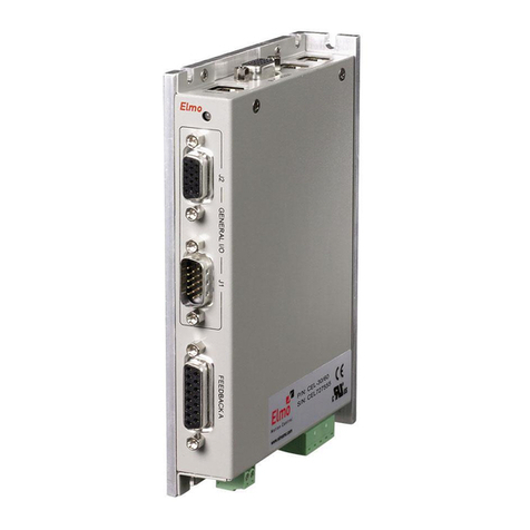
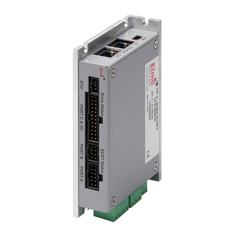
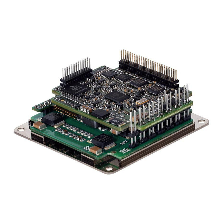
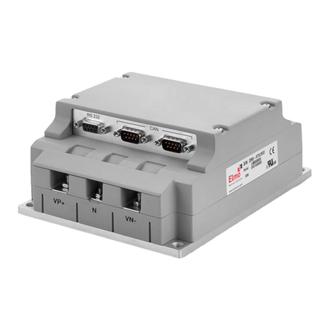
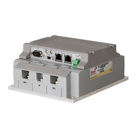
Elmo TUB Series User manual

Artisan Technology Group is your source for quality
new and certied-used/pre-owned equipment
• FAST SHIPPING AND
DELIVERY
• TENS OF THOUSANDS OF
IN-STOCK ITEMS
• EQUIPMENT DEMOS
• HUNDREDS OF
MANUFACTURERS
SUPPORTED
• LEASING/MONTHLY
RENTALS
• ITAR CERTIFIED
SECURE ASSET SOLUTIONS
SERVICE CENTER REPAIRS
Experienced engineers and technicians on staff
at our full-service, in-house repair center
WE BUY USED EQUIPMENT
Sell your excess, underutilized, and idle used equipment
We also offer credit for buy-backs and trade-ins
www.artisantg.com/WeBuyEquipment
REMOTE INSPECTION
Remotely inspect equipment before purchasing with
our interactive website at www.instraview.com
LOOKING FOR MORE INFORMATION?
Visit us on the web at www.artisantg.com for more
information on price quotations, drivers, technical
specications, manuals, and documentation
Contact us: (888) 88-SOURCE | sales@artisantg.com | www.artisantg.com
SM
View
Instra

Notice
This guide is delivered subject to the following conditions and restrictions:
•This guide contains proprietary information belonging to Elmo Motion Control Ltd. Such
information is supplied solely for the purpose of assisting users of the Tuba servo drive in
its installation.
•The text and graphics included in this manual are for the purpose of illustration and
reference only. The specifications on which they are based are subject to change without
notice.
•Elmo Motion Control and the Elmo Motion Control logo are trademarks of Elmo Motion
Control Ltd.
•Information in this document is subject to change without notice.
Document no. MAN-TUBIG (Ver. 1.503)
Copyright 2017
Elmo Motion Control Ltd.
All rights reserved.
Catalog Number
Nominal AC
Operating Voltage
Continuous Current
(Amps)
Version :
Blank =Standard
A = Advanced
Feedback:
Blank =Incremental
Encoder
and/or Halls
R = Resolver
TUB- A
X/YYYR
T = Tachometer &
Potentiometer
I = Interpolated
Analog
Encoder
Q = Encoder
Absolute

Revision History
Version Date Details
1.0 April 2005 Initial release
1.1 September 2005 BR1 and BR2 connected to DC Link
1.11 September 2006 Correction to Encoder Outputs in Section 4.9.8
1.12 October 2006 Correction to Interpolated Analog Encoder
1.2 March 2007 Added Absolute Encoder information
1.3 April 2008 Updated Power Ratings Table in Section 4.5
1.4 March 2010 MTCR 07-009-56: Added note to Section 3.4.8.1
1.5 July 2012 Formatted according to the new template
1.501 February 2013 Added a caution and recommendation on the type of
cleaning solution to use for the Elmo unit.
1.502 July 2014 General format changes
1.503 October 2017 Updated the Warranty Information section 1.5 and the
part number label in section 3.2

Elmo Worldwide
Head Office
Elmo Motion Control Ltd.
60 Amal St., P.O. Box 3078, Petach Tikva 4951360
Israel
Tel: +972 (3) 929-2300 • Fax: +972 (3) 929-2322 • info-il@elmomc.com
North America
Elmo Motion Control Inc.
42 Technology Way, Nashua, NH 03060
USA
Tel: +1 (603) 821-9979 • Fax: +1 (603) 821-9943 • info-us@elmomc.com
Europe
Elmo Motion Control GmbH
Steinkirchring 1, D-78056, Villingen-Schwenningen
Germany
Tel: +49 (0) 7720-85 77 60 • Fax: +49 (0) 7720-85 77 70 • info-de@elmomc.com
China
Elmo Motion Control Technology (Shanghai) Co. Ltd.
Room 1414, Huawen Plaza, No. 999 Zhongshan West Road, Shanghai (200051)
China
Asia Pacific
Elmo Motion Control APAC Ltd.
B-601 Pangyo Innovalley, 621 Sampyeong-dong, Bundang-gu, Seongnam-si, Gyeonggi-do,
South Korea (463-400)

Tuba Installation Guide
MAN-TUBIG (Ver. 1.503) 5
Table of Contents
Chapter 1: Safety Information .......................................................................................... 8
1.1. Warnings......................................................................................................................... 9
1.2. Cautions.......................................................................................................................... 9
1.3. Directives and Standards.............................................................................................. 10
1.4. CE Marking Conformance.............................................................................................10
1.5. Warranty Information .................................................................................................. 10
Chapter 2: Introduction ................................................................................................. 11
2.1. Drive Description .......................................................................................................... 11
2.2. Product Features ..........................................................................................................11
2.2.1. Current Control.............................................................................................. 11
2.2.2. Velocity Control .............................................................................................12
2.2.3. Position Control .............................................................................................12
2.2.4. Advanced Position Control (Advanced model only) ......................................12
2.2.5. Communication Options................................................................................12
2.2.6. Feedback Options .......................................................................................... 13
2.2.7. Fault Protection ............................................................................................. 13
2.3. System Architecture .....................................................................................................14
2.4. How to Use this Guide.................................................................................................. 15
Chapter 3: Installation ................................................................................................... 16
3.1. Before You Begin ..........................................................................................................16
3.1.1. Site Requirements .........................................................................................16
3.1.2. Hardware Requirements ...............................................................................16
3.1.2.1. AC Input Requirements.................................................................16
3.1.2.2. Recommended Wire Cross-Sections (All Models) ........................16
3.1.2.3. Power Connectors ........................................................................ 17
3.1.2.4. Communication Connectors ......................................................... 17
3.1.2.5. Feedback and I/O Connectors ...................................................... 18
3.1.2.6. Other Items Needed .....................................................................19
3.2. Unpacking the Drive Components................................................................................ 19
3.3. Mounting the Tuba....................................................................................................... 20
3.3.1. Mounting Directly onto a Wall ...................................................................... 20
3.3.2. Mounting on a DIN Rail.................................................................................. 21
3.4. Connecting the Cables.................................................................................................. 22
3.4.1. Wiring the Tuba .............................................................................................22
3.4.2. Connecting the Power Cables........................................................................ 26
3.4.2.1. Connecting the Motor Cable ........................................................ 27
3.4.2.2. Connecting the Main Power Cable ............................................... 28
3.4.2.3. Connecting the DC Link Cable.......................................................28
3.4.3. Connecting the Auxiliary Supply Cable (24 V) ...............................................29

Tuba Installation Guide Table of Contents
MAN-TUBIG (Ver. 1.503) 6
3.4.4. Feedback and Control Cable Assemblies....................................................... 30
3.4.5. Main Feedback Cable (Feedback A)...............................................................30
3.4.6. Main and Auxiliary Feedback Combinations .................................................39
3.4.7. Auxiliary Feedback (FEEDBACK B).................................................................. 41
3.4.7.1. Main Encoder Buffered Outputs or Emulated Encoder Outputs
Option on FEEDBACK B (YA[4]=4) ................................................. 41
3.4.7.2. Differential Auxiliary Encoder Input Option on FEEDBACK B
(YA[4]=2) ....................................................................................... 43
3.4.7.3. Single-Ended Auxiliary Input Option on FEEDBACK B -(YA[4]=2) 45
3.4.7.4. Pulse-and-Direction Input Option on FEEDBACK B - (YA[4]=0) ....47
3.4.8. I/O Cables ......................................................................................................50
3.4.8.1. Analog Inputs................................................................................ 50
3.4.8.2. Digital Inputs (on the GENERAL I/O Port) ..................................... 51
3.4.8.3. Digital Outputs (on the COMMITTED I/O Port) ............................ 54
3.4.9. Communication Cables.................................................................................. 56
3.4.9.1. RS-232 Communication (on the COMM.1 Port) ........................... 56
3.4.9.2. CAN Communication (on the COMM.2 Ports)..............................57
3.5. Powering Up ................................................................................................................. 59
3.6. Initializing the System................................................................................................... 59
Chapter 4: Technical Specifications ................................................................................ 60
4.1. Features........................................................................................................................ 60
4.1.1. Motion Control Modes ..................................................................................60
4.1.2. Advanced Positioning Motion Control Modes .............................................. 60
4.1.3. Advanced Filters and Gain Scheduling........................................................... 60
4.1.4. Fully Programmable....................................................................................... 60
4.1.5. Feedback Options .......................................................................................... 61
4.1.6. Input/Output ................................................................................................. 61
4.1.7. Built-In Protection .........................................................................................62
4.2. Tuba Dimensions .......................................................................................................... 63
4.3. Mounting Dimensions .................................................................................................. 64
4.4. Mechanical Specifications ............................................................................................ 64
4.5. Power Ratings...............................................................................................................65
4.6. Environmental Conditions............................................................................................ 65
4.7. Tuba Connections ......................................................................................................... 66
4.7.1. Auxiliary Supply .............................................................................................67
4.8. Control Specifications...................................................................................................67
4.8.1. Current Loop.................................................................................................. 67
4.8.2. Velocity Loop ................................................................................................. 68
4.8.3. Position Loop .................................................................................................68
4.9. Feedbacks ..................................................................................................................... 69
4.9.1. Feedback Supply Voltage...............................................................................69
4.9.2. Incremental Encoder Input............................................................................69
4.9.3. Digital Halls .................................................................................................... 70
4.9.4. Interpolated Analog (Sine/Cosine) Encoder .................................................. 70
Tuba Installation Guide Table of Contents
MAN-TUBIG (Ver. 1.503) 7
4.9.5. Resolver ......................................................................................................... 71
4.9.6. Tachometer....................................................................................................71
4.9.7. Potentiometer ...............................................................................................72
4.9.8. Encoder Outputs............................................................................................ 72
4.10. I/Os ............................................................................................................................... 73
4.10.1. Digital Input Interfaces (on the GENERAL I/O port) ......................................73
4.10.2. Digital Output Interface (on the COMMITTED I/O port) ...............................75
4.10.3. Analog Input .................................................................................................. 76
4.11. Communications...........................................................................................................77
4.12. Pulse-Width Modulation (PWM).................................................................................. 77
4.13. Single-Phase Operation ................................................................................................ 77
4.14. Compliance with Standards..........................................................................................78

Tuba Installation Guide
MAN-TUBIG (Ver. 1.503)
www.elmomc.com
8
Chapter 1:
Safety Information
In order to achieve the optimum, safe operation of the Tuba servo drive, it is imperative that
you implement the safety procedures included in this installation guide. This information is
provided to protect you and to keep your work area safe when operating the Tuba and
accompanying equipment.
Please read this chapter carefully before you begin the installation process.
Before you start, ensure that all system components are connected to earth ground. Electrical
safety is provided through a low-resistance earth connection.
Only qualified personnel may install, adjust, maintain and repair the servo drive. A qualified
person has the knowledge and authorization to perform tasks such as transporting, assembling,
installing, commissioning and operating motors.
The Tuba servo drive contains electrostatic-sensitive components that can be damaged if
handled incorrectly. To prevent any electrostatic damage, avoid contact with highly insulating
materials, such as plastic film and synthetic fabrics. Place the product on a conductive surface
and ground yourself in order to discharge any possible static electricity build-up.
To avoid any potential hazards that may cause severe personal injury or damage to the product
during operation, keep all covers and cabinet doors shut.
The following safety symbols are used in this manual:
Warning:
This information is needed to avoid a safety hazard, which might cause bodily
injury.
Caution:
This information is necessary for preventing damage to the product or to other
equipment.

Tuba Installation Guide Safety Information
MAN-TUBIG (Ver. 1.503)
www.elmomc.com
9
1.1. Warnings
•To avoid electric arcing and hazards to personnel and electrical contacts, never
connect/disconnect the servo drive while the power source is on.
•Power cables can carry a high voltage, even when the motor is not in motion. Disconnect
the Tuba from all voltage sources before it is opened for servicing.
•The Tuba servo drive contains grounding conduits for electric current protection. Any
disruption to these conduits may cause the instrument to become hot (live) and dangerous.
•After shutting off the power and removing the power source from your equipment, wait at
least 1 minute before touching or disconnecting parts of the equipment that are normally
loaded with electrical charges (such as capacitors or contacts). Measuring the electrical
contact points with a meter, before touching the equipment, is recommended.
1.2. Cautions
•The Tuba servo drive contains hot surfaces and electrically-charged components during
operation.
•The maximum AC/DC power supply connected to the instrument must comply with the
parameters outlined in this guide.
•The TUB-x/230 series is designed to operate from a single-phase 115 VAC source or from a
single- or three-phase 230 VAC source.
The TUB-x/460 series is designed to operate from a three-phase 400 or 460 VAC source.
The Tuba can be connected directly to the line voltage. An isolation transformer is not
needed.
•The Tuba drive must be connected to an approved 24 VDC auxiliary power supply through a
line that is separated from hazardous live voltages using reinforced or double insulation in
accordance with approved safety standards.
•Before switching on the Tuba, verify that all safety precautions have been observed and
that the installation procedures in this manual have been followed.
•Do not clean any of the Tuba drive's soldering with solvent cleaning fluids of pH greater
than 7 (8 to 14). The solvent corrodes the plastic cover causing cracks and eventual damage
to the drive's PCBs.
Elmo recommends using the cleaning fluid Vigon-EFM which is pH Neutral (7).
For further technical information on this recommended cleaning fluid, select the link:
http://www.zestron.com/fileadmin/zestron.com-usa/daten/electronics/Product_TI1s/TI1-
VIGON_EFM-US.pdf

Tuba Installation Guide Safety Information
MAN-TUBIG (Ver. 1.503)
www.elmomc.com
10
1.3. Directives and Standards
The Tuba conforms to the following industry safety standards:
Safety Standard Item
Approved IEC/EN 61800-5-1, Safety Adjustable speed electrical power drive systems
Recognized UL 508C Power Conversion Equipment
In compliance with UL 840 Insulation Coordination Including Clearances and
Creepage Distances for Electrical Equipment
In compliance with UL 60950-1
(formerly UL 1950)
Safety of Information Technology Equipment
Including Electrical Business Equipment
In compliance with EN 60204-1 Low Voltage Directive 73/23/EEC
The Tuba servo drive has been developed, produced, tested and documented in accordance
with the relevant standards. Elmo Motion Control is not responsible for any deviation from the
configuration and installation described in this documentation. Furthermore, Elmo is not
responsible for the performance of new measurements or ensuring that regulatory
requirements are met.
1.4. CE Marking Conformance
The Tuba servo drive is intended for incorporation in a machine or end product. The actual end
product must comply with all safety aspects of the relevant requirements of the European
Safety of Machinery Directive 98/37/EC as amended, and with those of the most recent
versions of standards EN 60204-1 and EN 292-2 at the least.
According to Annex III of Article 13 of Council Directive 93/68/EEC, amending Council Directive
73/23/EEC concerning electrical equipment designed for use within certain voltage limits, the
Tuba meets the provisions outlined in Council Directive 73/23/EEC. The party responsible for
ensuring that the equipment meets the limits required by EMC regulations is the manufacturer
of the end product.
1.5. Warranty Information
The products covered in this manual are warranted to be free of defects in material and
workmanship and conform to the specifications stated either within this document or in the
product catalog description. All Elmo drives are warranted for a period of 12 months from the
date of shipment. No other warranties, expressed or implied — and including a warranty of
merchantability and fitness for a particular purpose — extend beyond this warranty.

Tuba Installation Guide
MAN-TUBIG (Ver. 1.503)
www.elmomc.com
11
Chapter 2:
Introduction
This installation guide describes the Tuba servo drive and the steps for its wiring, installation
and powering up. Following these guidelines ensures maximum functionality of the drive and
the system to which it is connected.
2.1. Drive Description
The Tuba is a powerful servo drive that operates in digital current, velocity, position and
advanced position modes, in conjunction with a permanent-magnet synchronous brushless
motor or DC brush motor. The Tuba features flexible sinusoidal and trapezoidal commutation,
with vector control. The Tuba can operate as a stand-alone device or as part of a multi-axis
network in a distributed configuration.
The Tuba drive is set up and tuned using Elmo’s Composer software. This Windows-based
application enables users to quickly and simply configure the servo drive for optimal use with
their motor.
Power to the various models of Tuba is provided by a 115, 230, 3 x 230, 3 x 400 or 3x 460 VAC
source. A separate 24 VDC power supply serves as both the auxiliary supply and the backup
supply. This enables a safe and economical “power backup” feature that is essential for
positioning systems. An auxiliary 24 VDC power supply is required as the Tuba does not operate
without one.
Two variations of the Tuba are available: the Standard version and the Advanced version, which
features advanced positioning capabilities. Both versions operate with RS-232 and/or CAN
communication.
2.2. Product Features
2.2.1. Current Control
•Fully digital
•Sinusoidal commutation with vector control or trapezoidal commutation with encoder
and/or digital Hall sensors
•12-bit current loop resolution
•Automatic gain scheduling, to compensate for variations in the DC bus power supply

Tuba Installation Guide Introduction
MAN-TUBIG (Ver. 1.503)
www.elmomc.com
12
2.2.2. Velocity Control
•Fully digital
•Programmable PI and FFW (feed forward) control filters
•Sample rate two times current loop sample time
•“On-the-fly” gain scheduling
•Automatic, manual and advanced manual tuning and determination of optimal gain and
phase margins
2.2.3. Position Control
•Programmable PIP control filter
•Programmable notch and low-pass filters
•Position follower mode for monitoring the motion of the slave axis relative to a master axis,
via an auxiliary encoder input
•Pulse-and-direction inputs
•Sample time: four times that of current loop
•Fast event capturing inputs
2.2.4. Advanced Position Control (Advanced model only)
•Position-based and time-based ECAM mode that supports a non-linear follower mode, in
which the motor tracks the master motion using an ECAM table stored in flash memory
•PT and PVT motion modes
•Dual (position/velocity) loop
•Fast output compare (OC)
2.2.5. Communication Options
Depending on the application, Tuba users can select from two communication options:
•RS-232 serial communication
•CAN for fast communication in a multi-axis distributed environment

Tuba Installation Guide Introduction
MAN-TUBIG (Ver. 1.503)
www.elmomc.com
13
2.2.6. Feedback Options
•Incremental Encoder – up to 20 Mega-Counts (5 Mega-Pulse) per second
•Digital Halls – up to 2 kHz
•Incremental Encoder with Digital Halls for commutation – up to 20 Mega-Counts per
second for encoder
•Absolute Encoder
•Interpolated Analog (Sine/Cosine) Encoder – up to 250 kHz (analog signal)
Internal Interpolation – programmable up to x4096
Automatic Correction of:
•amplitude mismatch
•phase mismatch
•signals offset
Encoder outputs, buffered, differential.
•Resolver
Programmable 10 to 15 bit resolution
Up to 512 revolutions per second (RPS)
Encoder outputs, buffered, differential
•Tachometer and Potentiometer
Two inputs for Tachometer Feedback:
Up to ±50 VDC
Up to ±20 VDC
Potentiometer Feedback:
0 to 5 V voltage range
Resistance: 100 Ωto 1000 Ω
•Elmo drives provide supply voltage for all the feedback options.
2.2.7. Fault Protection
The Tuba includes built-in protection against possible fault conditions, including:
•Software error handling
•Status reporting for a large number of possible fault conditions
•Protection against conditions such as excessive temperature, under/over voltage, loss of
commutation signal, short circuits between the motor power outputs and between each
output and power input/return
•Recovery from loss of commutation signals and from communication errors

Tuba Installation Guide Introduction
MAN-TUBIG (Ver. 1.503)
www.elmomc.com
14
2.3. System Architecture
Auxiliary
Power
Supply
PWM
Controller
Power Stage
Protection Current
Feedback
Incremental
Encoder
24 VDC
I/Os
Incremental Encoder
Buffered Output
or
Emulated Output
Resolver
Analog
Encoder
Auxiliary
Encoder
or
or
Potentiometer
Tachometer
or
or
Communication
RS 232 and CANopen
Figure 1: Tuba System Block Diagram

Tuba Installation Guide Introduction
MAN-TUBIG (Ver. 1.503)
www.elmomc.com
15
2.4. How to Use this Guide
In order to install and operate your Elmo Tuba servo drive, you will use this manual in
conjunction with a set of Elmo documentation. Installation is your first step; after carefully
reading the safety instructions in the first chapter, the following chapters provide you with
installation instructions as follows:
•Chapter 3, Installation, provides step-by-step instructions for unpacking, mounting,
connecting and powering up the Tuba.
•Chapter, Technical Specifications,lists all the drive ratings and specifications.
Upon completing the instructions in this guide, your Tuba servo drive should be successfully
mounted and installed. From this stage, you need to consult higher-level Elmo documentation
in order to set up and fine-tune the system for optimal operation. The following figure
describes the accompanying documentation that you will require.
Figure 2: Elmo Documentation Hierarchy
As depicted in the previous figure, this installation guide is an integral part of the Tuba
documentation set, comprising:
•The Composer Software Manual, which includes explanations of all the software tools that
are part of Elmo’s Composer software environment.
•The SimplIQ Command Reference Manual, which describes, in detail, each software
command used to manipulate the Tuba motion controller.
•The SimplIQ Software Manual, which describes the comprehensive software used with the
Tuba.

Tuba Installation Guide
MAN-TUBIG (Ver. 1.503)
www.elmomc.com
16
Chapter 3:
Installation
The Tuba must be installed in a suitable environment and properly connected to its voltage
supplies and the motor.
3.1. Before You Begin
3.1.1. Site Requirements
You can guarantee the safe operation of the Tuba by ensuring that it is installed in an
appropriate environment.
Feature Value
Ambient operating temperature 0 °C to 40 °C (32 °F to 104 °F)
Maximum relative humidity 90% non-condensing
Operating area atmosphere No flammable gases or vapors permitted in area
Models for extended environmental conditions are available.
Caution:
The Tuba dissipates its heat by forced ventilation (fan). The maximum operating
ambient temperature of 0 °C to 40 °C (32 °F to 104 °F) must not be exceeded.
3.1.2. Hardware Requirements
3.1.2.1. AC Input Requirements
Circuit Breakers &
Contacts
Three-Phase Supply
Voltage
Single-Phase Supply
Voltage
Circuit breaker current rating 150% to 200% of drive
current
200% to 300% of drive
current
Circuit breaker voltage rating 250 VAC / 480 VAC depending upon operating AC voltage
Contactor Up to 150% of drive current Up to 200% of drive current
3.1.2.2. Recommended Wire Cross-Sections (All Models)
Feature Connection Details
AC input AC1, AC2, AC3 4 to 5 mm2, 10 to 12 AWG
Motor M1, M2, M3 4 to 5 mm2, 10 to 12 AWG
Protective earth PE, PE 4 to 5 mm2, 10 to 12 AWG
Auxiliary power 24V +, – 0.5 to 1 mm2, 18 to 20 AWG

Tuba Installation Guide Installation
MAN-TUBIG (Ver. 1.503)
www.elmomc.com
17
3.1.2.3. Power Connectors
Component Connector Described
in Section
Photo
External DC Link
Cable
B1, B2 on External DC
Link Cable
3.4.2.3
Main Power Cable PE, AC1, AC2, and AC3
on Power Connector
3.4.2.2
Motor Cable M1, M2, M3, PE
on Power Connector
3.4.2.1
Auxiliary Power
Cable
24V +, -3.4.3
3.1.2.4. Communication Connectors
Component Port on Tuba Described
in Section
Diagram
RS232
Communication
Cable
COMM. 1 3.4.9.1
CAN
Communication
cable(s)
COMM. 2 3.4.9.2

Tuba Installation Guide Installation
MAN-TUBIG (Ver. 1.503)
www.elmomc.com
18
3.1.2.5. Feedback and I/O Connectors
Component Port on Tuba Described
in Section
Diagram
Analog Inputs
(if needed)
ANALOG I/O 3.4.8.1
CEL0040A-DWG
COR016A
Digital Outputs
Cable
(if needed)
COMMITTED I/O 3.4.8.2
Digital Inputs Cable
(if needed)
GENERAL I/O 3.4.8.3
Main Feedback
Cable
FEEDBACK A 3.4.5
Auxiliary Feedback
Cable (if needed)
FEEDBACK B 3.4.7
COR016A

Tuba Installation Guide Installation
MAN-TUBIG (Ver. 1.503)
www.elmomc.com
19
3.1.2.6. Other Items Needed
Component Diagram
PC for drive setup and tuning
Motor data sheet or manual
3.2. Unpacking the Drive Components
Before you begin working with the Tuba system, verify that you have all of its components, as
follows:
•The Tuba servo drive
•The Composer software and software manual
The Tuba is shipped in a cardboard box with Styrofoam protection.
To unpack the Tuba:
1. Carefully remove the servo drive from the box and the Styrofoam.
2. Check the drive to ensure that there is no visible damage to the instrument. If any damage
has occurred, report it immediately to the carrier that delivered your drive.
3. To ensure that the Tuba you have unpacked is the appropriate type for your requirements,
locate the part number sticker on the side of the Tuba. It looks like this:
The P/N number at the top gives the type designation as follows:
4. Verify that the Tuba type is the one that you ordered, and ensure that the voltage meets
your specific requirements.
Nominal AC
Operating Voltage
Continuous Current
(Amps)
Version
:
Blank
=
Standard
A
=
Advanced
Feedback:
Blank
=
Incremental
Encoder
and/or Halls
R
=
Resolver
TUB-
A
X/YYY
R
T
=
Tachometer &
Potentiometer
I
=
Interpolated
Analog
Encoder
Q
=
Encoder
Absolute
Table of contents
Other Elmo Servo Drive manuals

Elmo
Elmo SimplIQ Series User manual

Elmo
Elmo Gold Whistle Series User manual

Elmo
Elmo Gold Drum HV User manual

Elmo
Elmo Gold DC Trombone User manual

Elmo
Elmo SimplIQ Series User manual

Elmo
Elmo Cello User manual

Elmo
Elmo SimpliQ Line User manual

Elmo
Elmo Gold DC Bell User manual

Elmo
Elmo Gold Series User manual

Elmo
Elmo 30/60 User manual
Popular Servo Drive manuals by other brands

Delta
Delta ASDA-A2 Series instruction sheet

Delta
Delta ASD-A2R-0221 Series user manual

LS ELECTRIC
LS ELECTRIC L7NH Series user manual

Kollmorgen
Kollmorgen AKM1 instruction manual

AutoVac
AutoVac VACUUM IQ VFD Series quick start guide

Rockwell Automation
Rockwell Automation Allen-Bradley Kinetix 300 2097-V31PR0 user manual