Harol VR150 User manual

INSTALLATION
ANDUSERGUIDE
MULTIFUNCTIONAL
SURFACE MOUNTED
ROLLER SHUTTER
VR150
Art. 061715
ZONWERING
SUN PROTECTION
ROLLUIKEN
ROLLER SHUTTERS
POORTEN
GATES

10/20 | 2
INSTALLATION MANUAL MULTIFUNCTIONAL SURFACE MOUNTED ROLLER SHUTTER VR150
TABLE OF CONTENTS
1. INTRODUCTION 3
2. GENERAL WARNINGS 3
3. GUARANTEE, TERMS AND CONDITIONS 4
4. REQUIREMENTS 4
5. ASSEMBLY IN 10 STEPS 5
5.1. Unpacking and checking 5
5.2. The wall cardan joint 6
5.3. Making attachment holes in the guide rails 7
5.4. Placing the guide rails on the consoles 8
5.5. Marking the drill holes 9
5.6. Drilling the attachment holes 10
5.7. Installing the shutter 10
5.8. Connections 11
5.9. Testing 13
5.10. Finish 14
6. REPLACING THE MESH NETTING IN 12 STEPS 15

10/20 | 3
INSTALLATION MANUAL MULTIFUNCTIONAL SURFACE MOUNTED ROLLER SHUTTER VR150
1. INTRODUCTION
The Harol surface mounted roller shutter is an ideal shutter for renovations.
It oers the possibility to have shutters installed even if there was no space provided
forshutters during the construction of the house.
This manual gives a step-by-step explanation on how to install these shutters.
2. GENERAL WARNINGS
!Please read the entire manual before starting with the installation. These instructions
have been drawn up for use by trained installers and therefore are not suitable for use
by amateurs or trainees.
!Always wear the appropriate safety clothing.
!Always take the necessary precautions. Ensure that you have a robust footing.
!Ensure that there is adequate light in the installation area. Remove obstacles and dirt.
Make sure that no other persons than the installers are present. Unauthorised persons
can get in the way or be at risk during the installation.
!While operating the shutter, make sure you have a clear view of the shutter at all times
to protect other persons against crush hazards. Beware of obstacles below the shutter.
!All electrical connections must be made according to the statutory provisions of the
relevant country. This is the responsibility of the installer.

10/20 | 4
INSTALLATION MANUAL MULTIFUNCTIONAL SURFACE MOUNTED ROLLER SHUTTER VR150
3. GUARANTEE, TERMS AND CONDITIONS
• Harol has endeavoured to design and manufacture this shutter in compliance with
the current CE standards. Always check that our version complies with your own
national standards institute.
• No rights can be derived from these instructions whatsoever. Technical modifications
are reserved without written notification.
• For large projects we strongly advise you to first fit one complete shutter before
fitting the remaining shutters. This will help detect any potential faults early on and
enable them to be remedied at the lowest possible cost.
• For our general terms and conditions of sale, please refer to the price list.
• Make sure the shutter box can always be opened so the mechanical parts inside can
be reached easily. If this rule is not respected, Harol cannot be held responsible for
the cost of demolition work, among other things.
Harol NV
Industriepark 3 – 3290 Diest
Belgium
+32 13 38 01 11
+32 13 31 48 03
info@harol.be
www.harol.com
4. REQUIREMENTS
• Ladders
• Drill with metal and masonry drills
• Screwdrivers and open-ended spanners
• Fastening bolts most suitable for the relevant base
• Tape measure, pencil, and level
• Voltmeter or 230 V testing lamp, testing cable with switch
• Metal saw
• Sizeable piece of cardboard or heavy plastic foil
• Silicone mastic
• Cutter

10/20 | 5
INSTALLATION MANUAL MULTIFUNCTIONAL SURFACE MOUNTED ROLLER SHUTTER VR150
5. ASSEMBLY IN 10 STEPS
5.1. Unpacking and checking
a. Check the package
Check the package for any damage before removing the complete packaging from
around the box and guide rails.
Be careful when cutting the straps with a knife. Opening the cardboard box carelessly
may result in damage to the paint.
b. Check the product
Before starting with the installation it is advisable to accurately check the contents
forcompleteness and for any transport damage.
c. Check the height and width
Measure the main dimensions:
• Width = measured from the back of the guide rails
• Height = total height
Check the width of the shutter box and measure the window opening. Verify that both
match the desired mounting position.
Also check the height of the guide rails (including the end stop), and make sure they
correspond to the height of the window.
10/20 | 6
INSTALLATION MANUAL MULTIFUNCTIONAL SURFACE MOUNTED ROLLER SHUTTER VR150
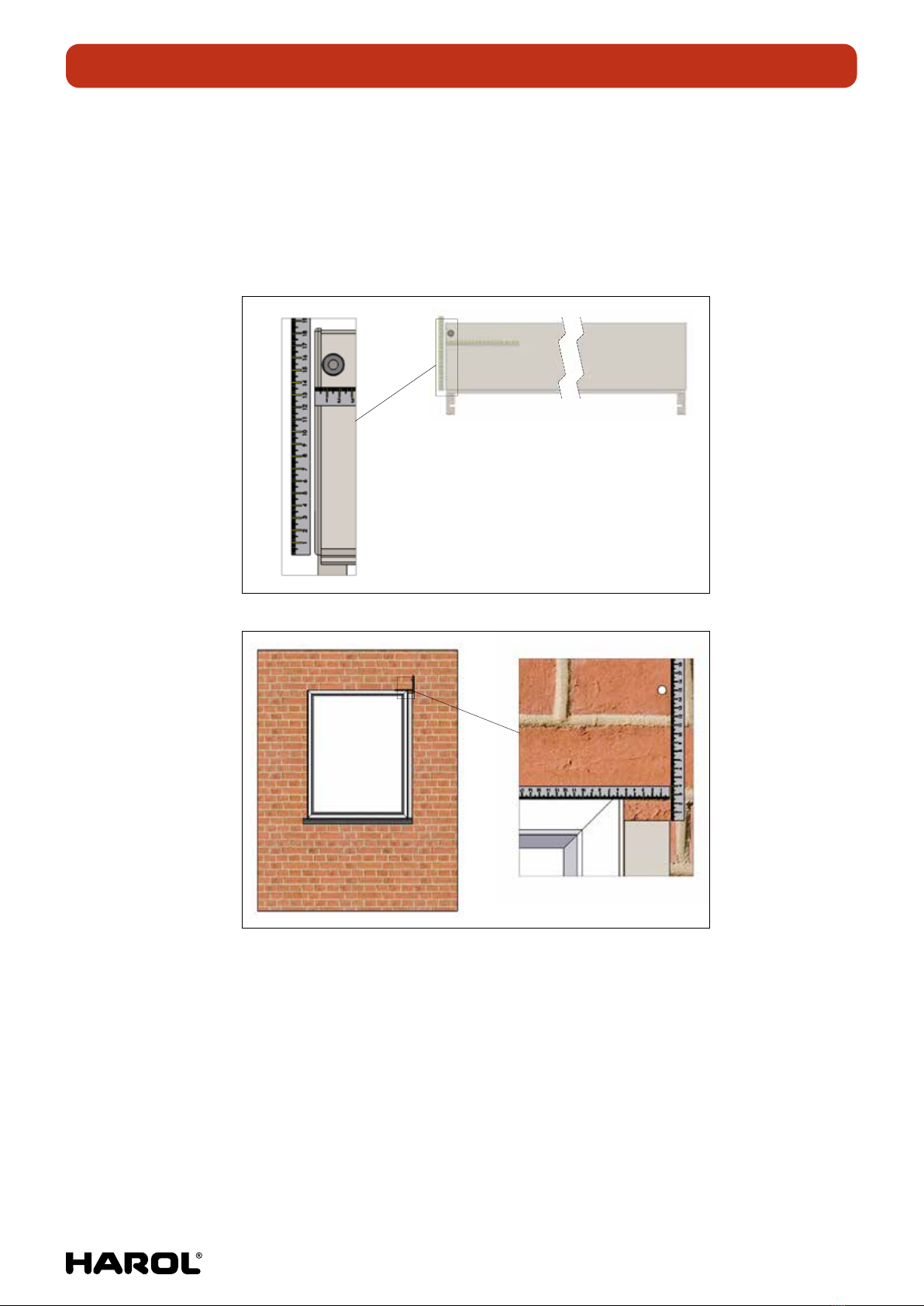
5.2. The wall cardan joint
− The cable duct or tape guide is usually found in the shutter unless otherwise requested.
It is important, however, to ensure there is a cardan joint before starting the installation.
− Measure the distance of the cardan joint (motor cable, gearbox, tape operation) on
the shutter box and mark the position on the wall or window frame. The easiest way
to determine this position is by placing a guide rail in the correct position against the
wall. Use the top of the guide rail as a point of reference.
A (1 : 1.5)
A (1 : 2)
− Carefully drill from the outside to the inside of the wall (bore hole 10 mm for motor
cable, 14 mm for crank, 20 mm for tape guide). A tube is pressed into the hole for
thetape guide to prevent damage to the tape.
− When drilling through the wall you will achieve the best results if, while drilling, someone
exerts some pressure against the inside of the wall with a piece of wood or something
similar. Use a rotating drill rather than a hammer drill for the last part.
− When drilling through the window frame make sure that you do not drill into the
glasssection!
10/20 | 7
INSTALLATION MANUAL MULTIFUNCTIONAL SURFACE MOUNTED ROLLER SHUTTER VR150
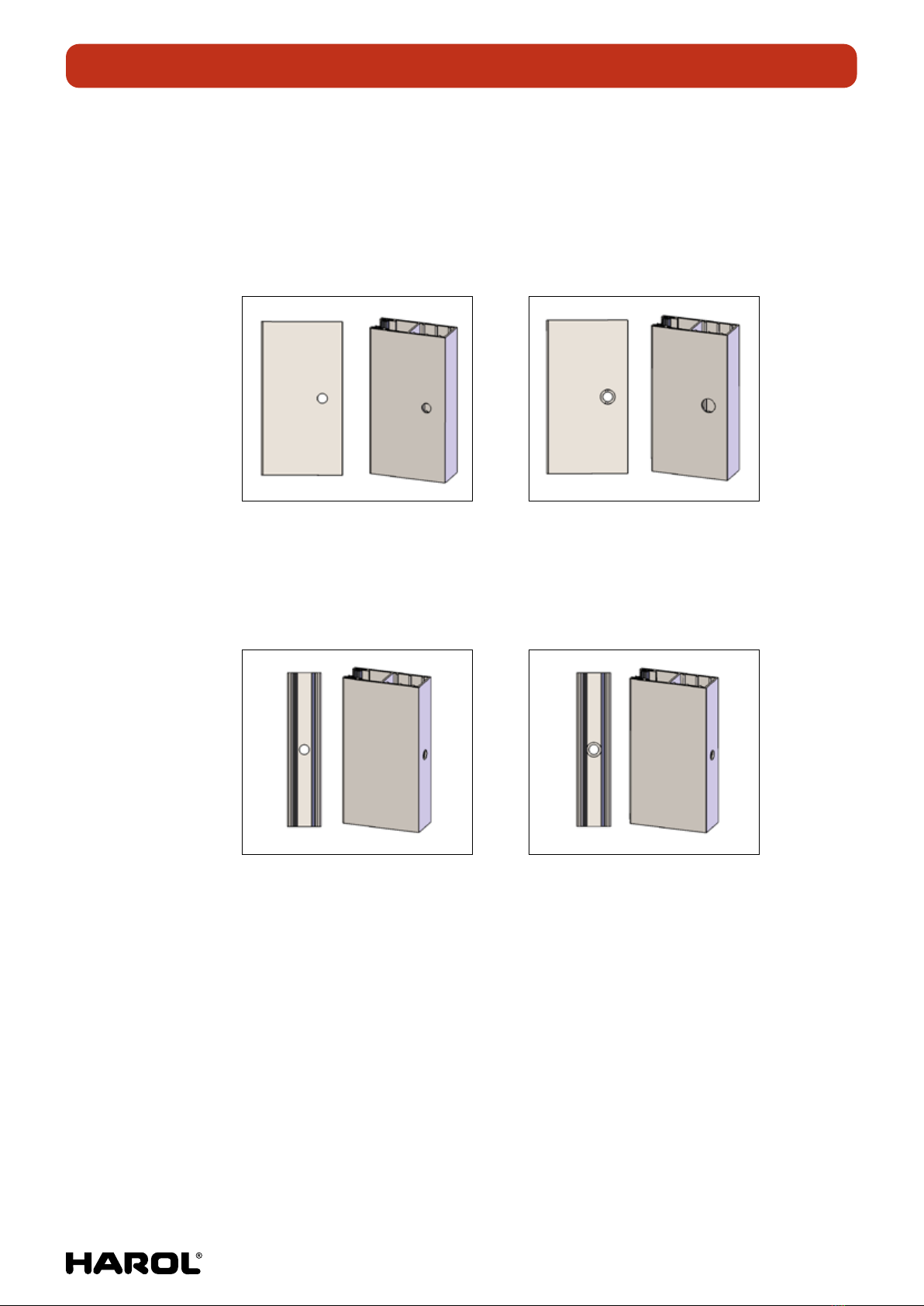
5.3. Making attachment holes in the guide rails
Determine where you want the attachment holes in the guide rail (3 for each metre
ofheight).
If the guide rail needs to be drilled from the side, then first drill a 6.5 mm hole sideways
through the hollow box and then drill a 9.5 mm hole in the front (after securing the
screws you can fill in the hole using the PVC buttons supplied).
Hole of 6.5 through both sides Hole of 9.5 through the front
If the guide rails need to be drilled from the back, start by drilling a 6.5 mm hole inside
the guide rail through the hollow box and then drill the inside front hole with a thicker
9.5 mm drill. Be careful not to damage the joints of the guide rail!
Hole of 6.5 through both sides Hole of 9.5 through the front
Always leave a distance of 8 cm or more from the top edge (pivot for console!).
Box model P has an opening in the pivot for the console (at 40 mm from the top
oftheguide rail) and this point can be used as the top screw hole.

10/20 | 8
INSTALLATION MANUAL MULTIFUNCTIONAL SURFACE MOUNTED ROLLER SHUTTER VR150
5.4. Placing the guide rails on the consoles
Remeasure the height and if necessary saw the guide rails to size.
Cut away the joint at the top of the guide rail, where you find the entry guide
oftheguide rail.
B (2.8 : 1)
If included, carefully remove the fork clamps on the bottom lath (and if necessary gently
pull down the bottom lath a little) and drop the pivots for the console into the hollow boxes
of the guide rails. Place the console with the pivots facing upwards on a piece of cardboard
on the floor. Then place the guide rails over the respective pivots for the console.
A (1 : 3)

10/20 | 9
INSTALLATION MANUAL MULTIFUNCTIONAL SURFACE MOUNTED ROLLER SHUTTER VR150
Turn everything around. Do this with at least two people so that both the guide rails and
the box are supported! If the box is not supported the pivots for the console may break o!
Then place everything against the wall or in the opening.
A (1 : 10)
5.5. Marking the drill holes
Mark the holes to be drilled for mounting the guide rails on the wall based on the
pre-drilled lateral guides. Always make sure that everything is level.
A (1 : 2)
B (1 : 10)

10/20 | 10
INSTALLATION MANUAL MULTIFUNCTIONAL SURFACE MOUNTED ROLLER SHUTTER VR150
5.6. Drilling the attachment holes
Remove the shutter from the wall and with at least two people place it carefully
onaflatsurface on a piece of cardboard. Be careful not to damage the paint!
Next, drill the screw holes and insert the correct rawlplugs.
Attention!
When drilling the guide rails against the window profile, do not drill
intotheglass!
A (1 : 5)
5.7. Installing the shutter
Pick up the shutter from the floor and – with at least two people – place it in the position
where you want to install it. Make sure that the motor cable (tape/cord) slides correctly
into the cardan joint.
A (1 : 5)
10/20 | 11
INSTALLATION MANUAL MULTIFUNCTIONAL SURFACE MOUNTED ROLLER SHUTTER VR150
Secure the fastening bolts of the guide rails and if possible also screw the consoles
tightly into the wall (and for larger dimensions also the box).
A (1 : 2)
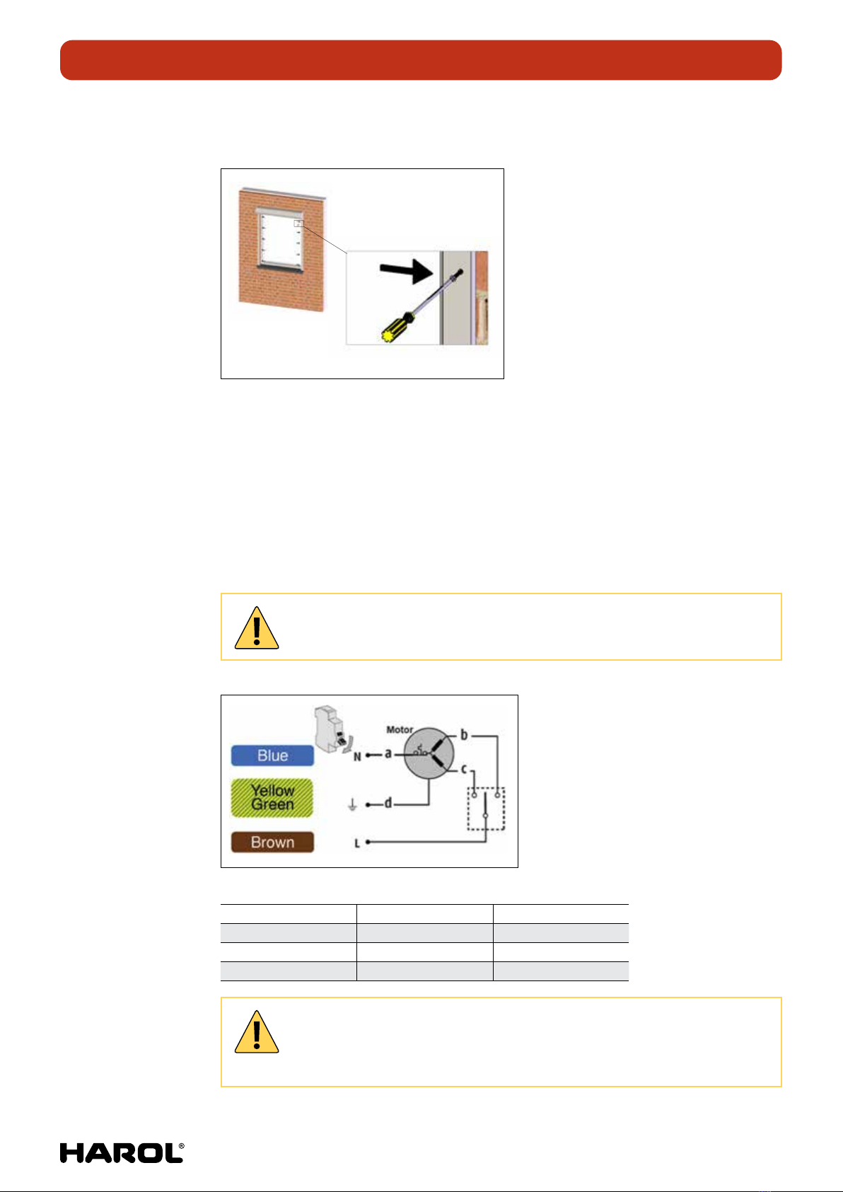
5.8. Connections
Motor:
• For motorised operation, the electrical connections must always be made according
to the applicable directives of the country where the shutter is being fitted.
Witheach motor the necessary diagrams (wiring diagram and alignment directives)
and installation instructions are included depending on the motor type and/or home
electronics accessories selected.
Wiring diagram for the standard OXIMO motor:
Attention!
Before connecting the motor make sure the power is disconnected.
a Blue Zero
b Brown Phase S1
c Black Phase S2
d Green/Yellow Earthing
Attention!
With a DVC with center conductor 120 or 121, in combination with an Oximo or
RS100 motor, the top point must be adjusted with the transmitter.

10/20 | 12
INSTALLATION MANUAL MULTIFUNCTIONAL SURFACE MOUNTED ROLLER SHUTTER VR150
Crank:
Push the square rod of the universal joint on the crank handle supplied into the previously
drilled bushing, until the bar stock is pushed far enough through the opening to engage
with the gear box. Determine the required length of the bar stock and shorten it if
necessary by cutting o the surplus length.
It is important to position the cardan joint in such a way that the bar stock does not
laterally chafe the wall of the bushing, at any point at any time. Also ensure that the bar
stock is positioned straight in the bushing and is not bent nor twisted. Drill the holes
(Ø3.2 mm) and screw the cardan joint tightly to the mounting surface.
A
A
B
A-A
B (1 : 2)
Slide the foldable crank handle over the round part of the cardan joint and use the split
pen to connect the two items. Slide the locking bush over the pin. Decide whether to
position the crank handle clip on the window frame or on the wall and secure the clip.
A
A (1 : 2)
B
B (1 : 2)
A
A (1 : 2)
B
B (1 : 2)
If a detachable crank with a rod coupling needs to be fitted: in this case the detachable
crank is provided with a cone-shaped end piece. A split pin is then inserted into the
suspended conical part of the cardan joint. The crank can then be attached or detached
from the cardan joint by turning the handle.
A
A (1 : 1)

10/20 | 13
INSTALLATION MANUAL MULTIFUNCTIONAL SURFACE MOUNTED ROLLER SHUTTER VR150
Tape:
Attaching the tape to the tape box
a. Roll down the shutter curtain all the way.
b. Make a slip in the tape.
c. Lead the tape through the covering plate to the roll-up mechanism.
d. Attach the tape to the relevant hook.
e. Unlock the roll-up spring.
f. Secure everything in/to the wall.
g. Roll the shutter curtain upwards.
Attention!
Make sure there are always 2 full rounds of tape on the holder!
5.9. Testing
Test the shutter by running the curtain up and down several times.
If all is OK, the work on the shutter can be finished.
A (1 : 1)
A (2 : 1)
B (2 : 1)
Step b Step c Step d Step e
10/20 | 14
INSTALLATION MANUAL MULTIFUNCTIONAL SURFACE MOUNTED ROLLER SHUTTER VR150
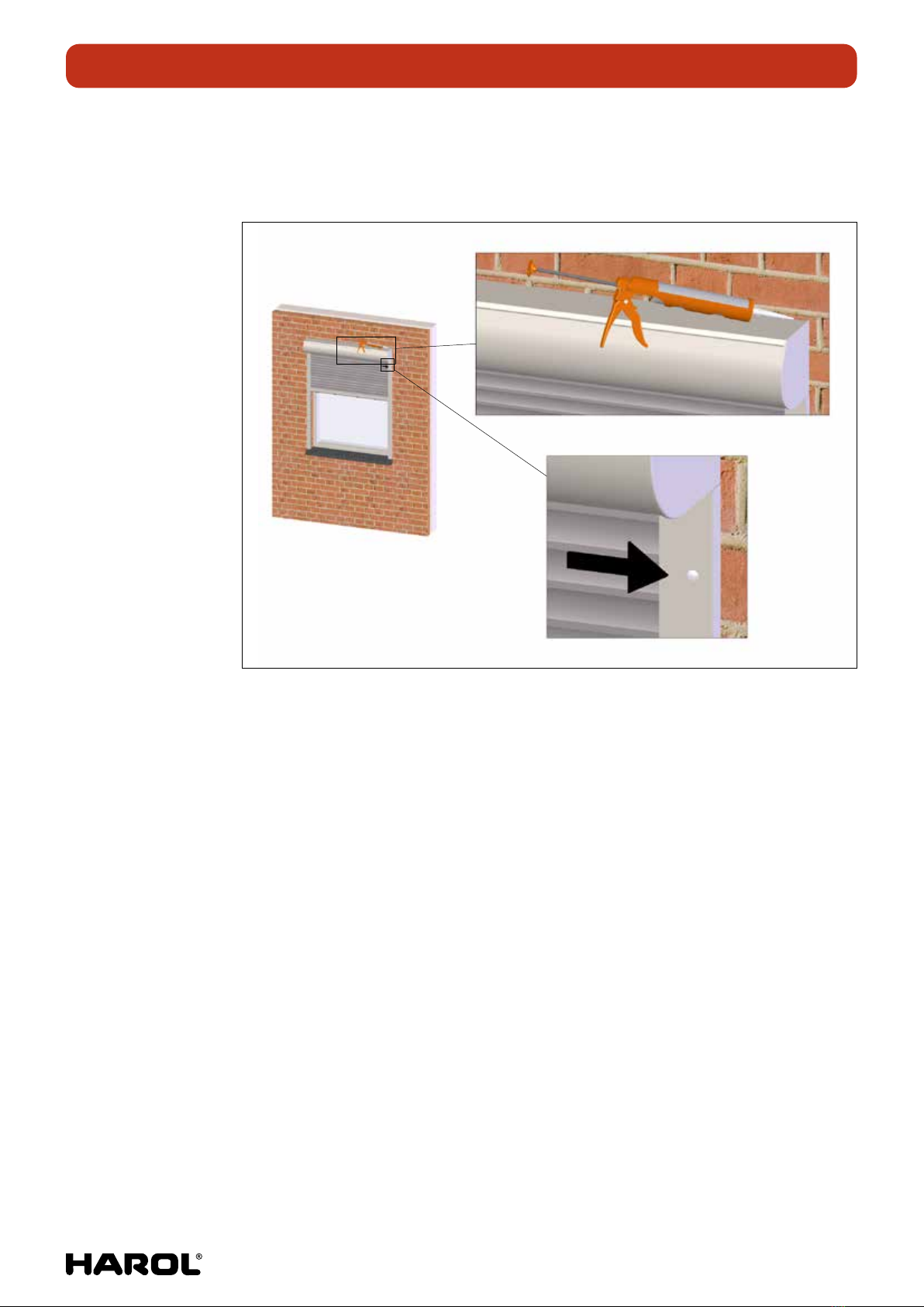
5.10. Finish
Place the PVC caps on the holes of the guide rail and use mastic to finish o the box
andthe guide rails.

10/20 | 15
INSTALLATION MANUAL MULTIFUNCTIONAL SURFACE MOUNTED ROLLER SHUTTER VR150
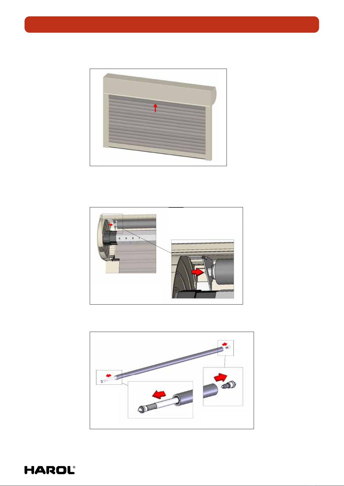
6. REPLACING THE MESH NETTING IN 12 STEPS
Number of persons: 2
1. Remove the inspection cover. Keep the shutter curtain rolled up. Pull the mesh netting
down halfway.
2. Hold the bottom lath askew and remove it from the guide rails.
3. Remove the bottom lath from the mesh netting. While doing so, hold the netting tight
or it will veer into the box.
10/20 | 16
INSTALLATION MANUAL MULTIFUNCTIONAL SURFACE MOUNTED ROLLER SHUTTER VR150
4. Completely release the shutter, and allow the mesh netting to carefully wind around
the axle.
5. Disconnect the shutter curtain from the axle.
Remove the little roller tube of the insect screen from its holders by pressing one
ofthe "buttons" on the left or right.
A
A (1 : 3)
B (1 : 1)
6. Remove the spring and the reverse side from the axle with the netting.
A (1 : 2)
B (1 : 2)
10/20 | 17
INSTALLATION MANUAL MULTIFUNCTIONAL SURFACE MOUNTED ROLLER SHUTTER VR150
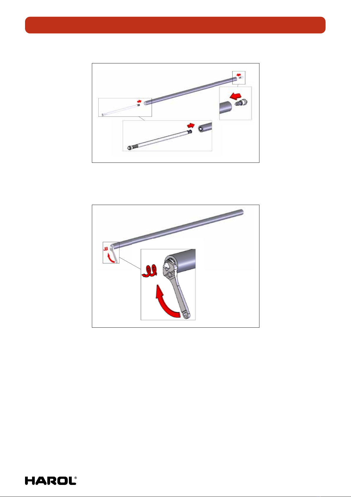
7. Insert this into the new axle with netting.
A (1 : 3)
B (1 : 2)
8. Tighten the spring using a key. In most cases this is after 18 to 19 rotations.
Removethe key carefully so that the spring is not released (it is released when
thespring fitting is pressed).
A (1 : 1.5)
10/20 | 18
INSTALLATION MANUAL MULTIFUNCTIONAL SURFACE MOUNTED ROLLER SHUTTER VR150
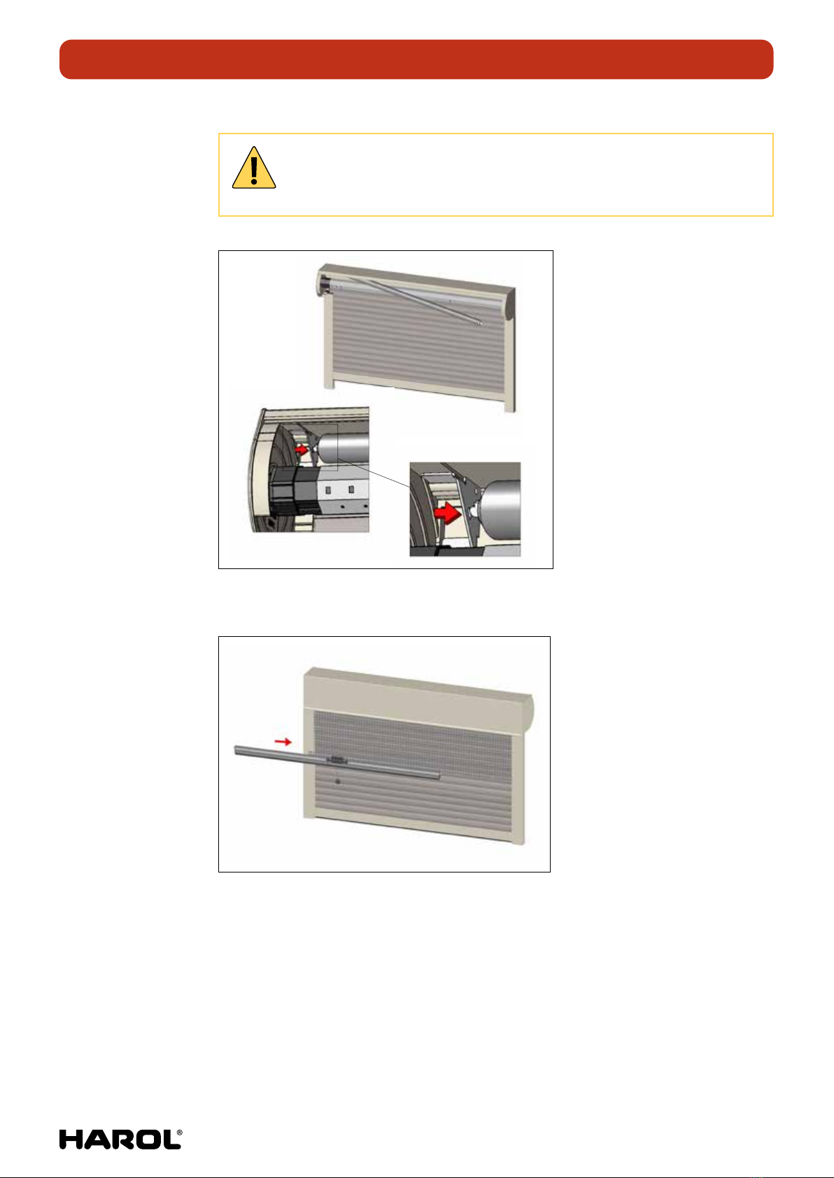
9. Insert the spring ends back into the mesh netting holders.
Attention!
First the spring side. When the spring is in place it will automatically release.
Take care to block the axle to prevent it from unwinding.
C
C (1 : 2)
E (1 : 1)
10. Roll down 50 cm of the netting to make it easy to attach the bottom lath to the netting.

10/20 | 19
INSTALLATION MANUAL MULTIFUNCTIONAL SURFACE MOUNTED ROLLER SHUTTER VR150
11. Reattach the shutter curtain to the axle and let the shutter curtain rewind completely.
Hold the bottom lath of the insect screen askew and insert it back into the guide rail.
12. Replace the bottom lath and netting in the correct position in the guide rail
andentryguide.
E
E (1 : 1)
Harol reserves the right to make any changes to the construction at all times without having to inform the client
beforehand and therefore without having to adapt existing installations.
Table of contents
Other Harol Indoor Furnishing manuals


Popular Indoor Furnishing manuals by other brands

Regency
Regency LWMS3015 Assembly instructions

Furniture of America
Furniture of America CM7751C Assembly instructions

Safavieh Furniture
Safavieh Furniture Estella CNS5731 manual

PLACES OF STYLE
PLACES OF STYLE Ovalfuss Assembly instruction

Trasman
Trasman 1138 Bo1 Assembly manual

Costway
Costway JV10856 manual


