Harris Dracon TS21 User manual
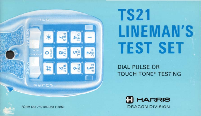
TS21
LINEMAN'S
TEST
SET
.
,-:
,-.-2g
;TpAq
DIA~
'PU
CSE
I&
*
TOUCH
TONE*
TESTING
*i
HARRIS
_1c1-
FOPIMNQ71012Mm)(l/86)
DRAGON
DIVISION
TCI Library: www.telephonecollectors.info
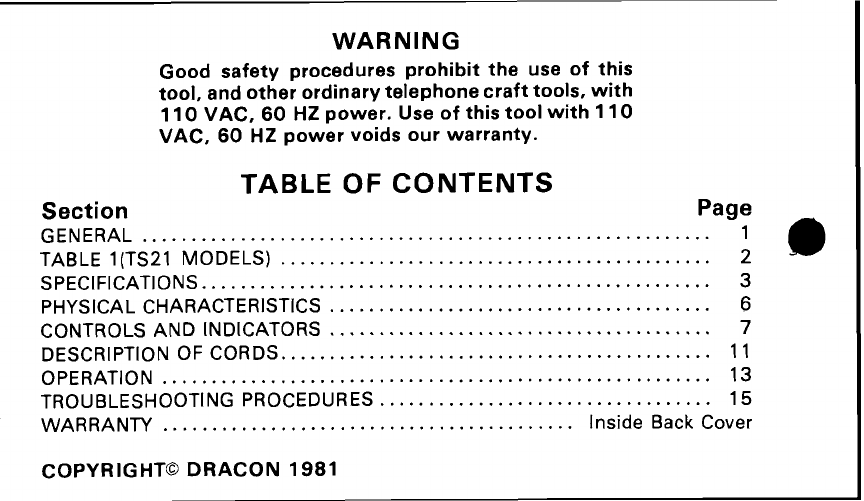
WARNING
Good safety procedures prohibit the use of this
tool, and other ordinary telephone crafttools, with
11
0
VAC, 60 HZ power. Use of this tool with 110
VAC, 60 HZ power voids our warranty.
TABLE OF CONTENTS
Section
Page
GENERAL
..........................................................
1
TABLE
1
(TS21 MODELS)
.................
.
...................
.
...
.
.
.
2
SPECIFICATIONS
....................................................
3
PHYSICAL CHARACTERISTICS
.......
.
..............
.
.........
.
......
6
CONTROLS AND INDICATORS
..
.
....
.
.......
.
.....
.
........
....
..
...
7
DESCRIPTION OF CORDS..
.......
.
..
.
........................
.
......
11
OPERATION
........................................................
13
TROUBLESHOOTING PROCEDURES
..
.
...
.
...........................
15
WARRANTY
...............
.
........
.
.........
.
....
.
.
.
Inside Back Cover
COPYRIGHT@DRACON 1981
TCI Library: www.telephonecollectors.info
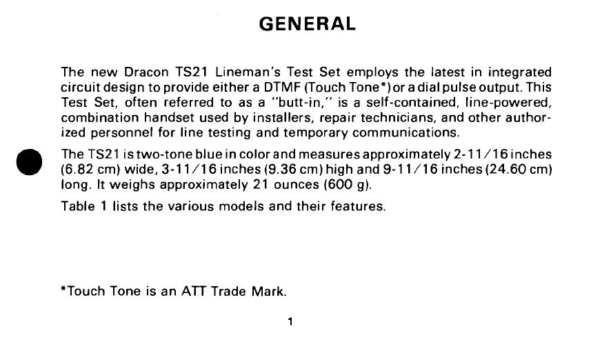
GENERAL
The new Dracon TS21 Lineman's Test Set employs the latest in integrated
circuit designtoprovide either a DTMF(TouchTone*)oradialpulseoutput.This
Test Set, often referred to as a "butt-in," is a self-contained, line-powered,
combination handset used by installers, repair technicians, and other author-
ized personnel for line testing and temporary communications.
The TS21 istwo-toneblueincolorandmeasuresapproximately 2-11/16 inches
(6.82cm)wide, 3-11/16 inches(9.36cm)highand 9-11/16 inches(24.60cm)
long. It weighs approximately 21 ounces (600g).
Table 1 lists the various models and their features.
"Touch Tone is an
ATT
Trade Mark.
1
TCI Library: www.telephonecollectors.info
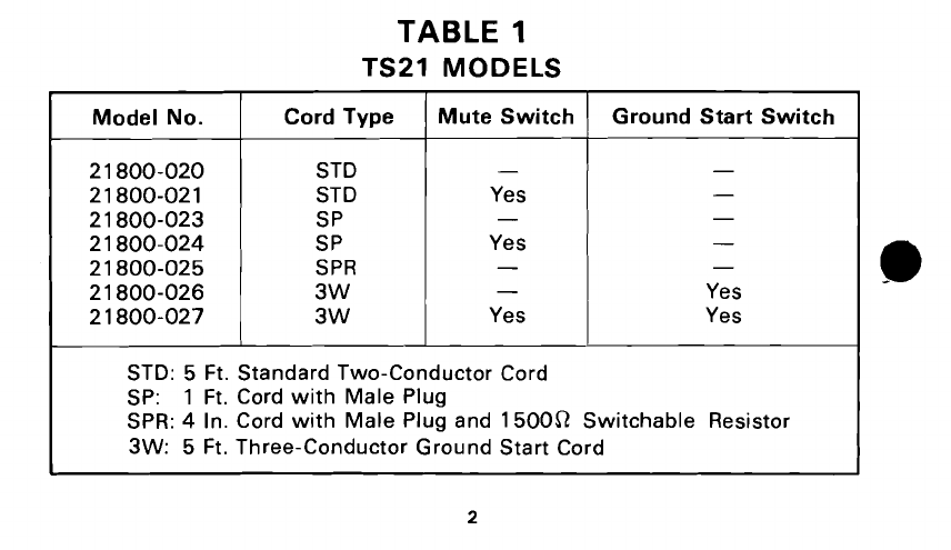
TABLE
1
TS21
MODELS
Model No.
21800-020
21800-02
1
21800-023
21800-024
21800-025
21800-026
2
1
800-027
STD:
5
Ft. Standard Two-Conductor Cord
SP:
1
Ft. Cord with Male Plug
SPR:
4
In. Cord with Male Plug and
150051
Switchable Resistor
3W: 5
Ft. Three-Conductor Ground Start Cord
Mute Switch
-
Yes
-
Yes
-
-
Yes
Cord Type
STD
STD
SP
SP
SPR
3W
3W
Ground Start Switch
-
-
-
-
-
Yes
Yes
TCI Library: www.telephonecollectors.info
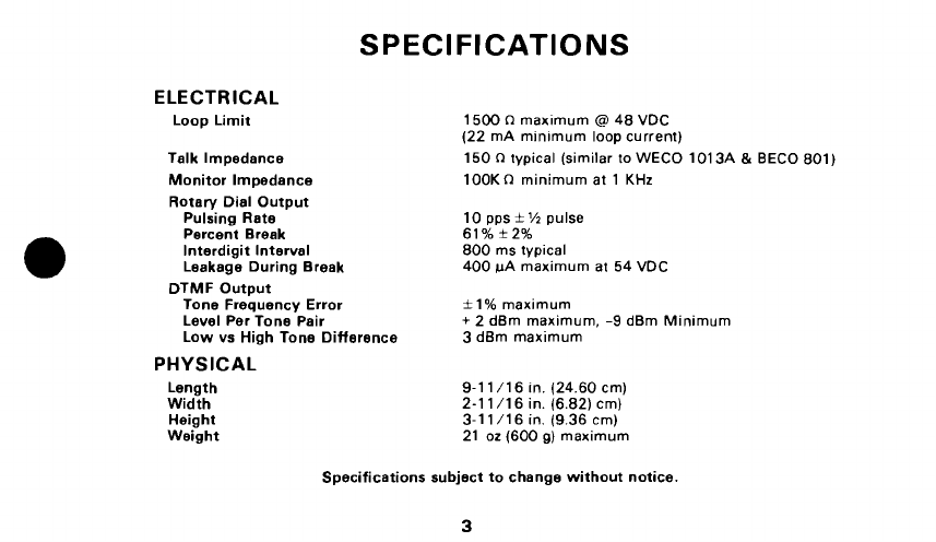
ELECTRICAL
Loop Limit
Talk Impedance
Monitor lmpedance
SPECIFICATIONS
Rotary Dial Output
Pulsing Rate
Percent Break
Interdigit Interval
Leakage During Break
DTMF Output
Tone Frequency Error
Level Per Tone Pair
Low vs High Tone Difference
PHYSICAL
Length
Width
Height
Weight
1500
n
maxlmum
@
48VDC
(22 mA min~mumloop current)
150
n
typical (similar to WECO 1013A
&
BECO 801)
lOOK
n
minimum at 1
KHz
10pps
*
%
pulse
61%*2%
800 ms typical
400 PA maximum at 54 VDC
+
1% maximum
+
2 dBm maximum, -9 dBm Minimum
3 dBm maximum
9-11/16 in. (24.60 cm)
2-11/16 in. (6.82)cm)
3-1
1/16 in. (9.36 cm)
21 oz (600
g)
maximum
Specifications subject tochange without notice.
TCI Library: www.telephonecollectors.info
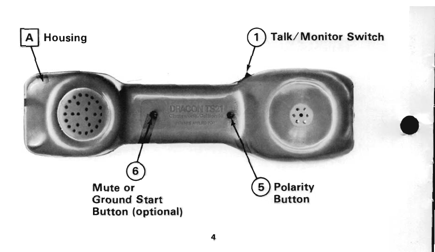
A
Housing
4
Talk/Monitor Switch
Mute or
Ground Start Button
Button (optional)
TCI Library: www.telephonecollectors.info

B
Belt Clip
A
2
Mode Tone/Pulse
Switch
d
TCI Library: www.telephonecollectors.info
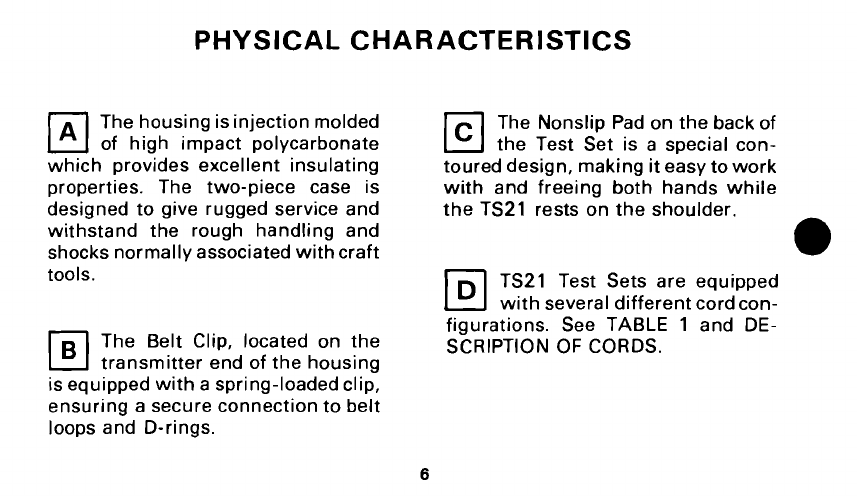
PHYSICAL CHARACTERISTICS
The housingisinjectionmolded
of high impact polycarbonate
which provides excellent insulating
properties. The two-piece case is
designed to give rugged service and
withstand the rough handling and
shocks normally associatedwithcraft
tools.
The Belt Clip, located on the
transmitter end of the housing
isequippedwith a spring-loadedclip,
ensuring a secure connectionto belt
loops and D-rings.
The Nonslip Pad on the back of
the Test Set is a special con-
toured design, making iteasy towork
with and freeing both hands while
the TS21 rests ;n the shoulder.
TS21 Test Sets are equipped
withseveral differentcordcon-
figurations. See TABLE 1 and DE-
SCRIPTION OF CORDS.
TCI Library: www.telephonecollectors.info
I
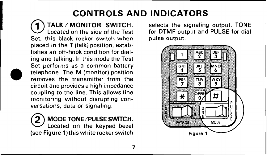
CONTROLS AND INDICATORS
TALK
/
MONITOR SWITCH.
selects the signaling output. TONE
Locatedon the side of the Test for DTMF output and PULSE for dial
Set, this black rocker switch when pulse output.
placed in the T(talk)position, estab-
lishes an off-hook condition for dial-
ing and talking. Inthis modethe Test
Set performs as a common battery
telephone. The
M
(monitor) position
removes the transmitter from the
circuit and providesa highimpedance
coupling to the line. This allows line
monitoring without disrupting con-
versations, data or signaling.
0
MODETONE/PULSE SWITCH.
Located on the keypad bezel
(seeFigure
1)
thiswhiterockerswitch
TCI Library: www.telephonecollectors.info

KEYPAD
IN/OUT
SWITCH.
when testing on dry circuits. The
Located on the keypad bezel OUT position must be usedwhen the
(see Figure
2),
this white rocker circuit voltage is
6V
or less, such as
switchselects either of twooperating when using "tones" or other test
modes. When set to the IN position, devices as a source of talk battery.
the Test Set operates as a modern
electronic telephone set. This mode
isused for all normalcommunication
functions. The OUTpositionbypasses
the Test Setelectronics, includingthe
keypad. In this mode signaling is not
possible, butthe Test Setwilloperate
at very low voltages, much like stan-
dard test sets currently in use. Line
testing is possible in either switch
position. The OUT position is recom-
mended when testing at or near the
loop limit
(1
500
R
@
48
VDC)
or
8
TCI Library: www.telephonecollectors.info
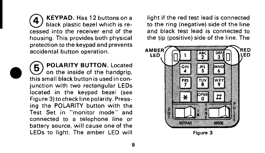
KEYPAD.
Has
12
buttons on a
black plastic bezel which is re-
cessed into the receiver end of the
housing. This provides both physical
protectiontothe keypadandprevents
accidental button operation.
POLARITY BUTTON.
Located
on the inside of the handgrip,
thissmall black buttonisusedincon-
junction with two rectangular LEDs
located in the keypad bezel (see
Figure
3)
tocheck linepolarity. Press-
ing the POLARITY button with the
Test Set in "monitor mode" and
connected to a telephone line or
battery source, will cause one of the
LEDs to light. The amber LED will
light if the red test lead is connected
to the ring (negative)side of the line
and black test lead is connected to
the tip (positive)side of the line.The
IED
.ED
Figure
3
TCI Library: www.telephonecollectors.info

red LED will light if thetest leadsare
reversed; that is, the red test lead
connected tothe tip(positive)andthe
black test lead connected tothe ring
(negative) side. In either case line
polarity has been determined.
CAUTION:
Operationof the PO-
LARITY button on a busy circuit may
cause annoying clicks or service in-
terruptions.
NOTE:
The DraconTS21 is NOT
polarity sensitive, allowing the Test
Set to function normally when con-
nected to the line ineither polarity.
MUTE BUTTON
(optional).
Located on the inside of the
handgrip just above the transmitter.
When pressed,this small blackbutton
mutes the transmitter, eliminating
sidetone and providing improved in-
telligibility in noisy locations.
GROUND START BUTTON
(optional).
Located inthesame
place as the optional MUTE button.
When pressed,thissmall blackbutton
connects the ground (green) lead to
the ring (red) lead of the special
three-conductor ground start cord,
initiating a ground start line seizure.
TCI Library: www.telephonecollectors.info

DESCRIPTION OF CORDS
STANDARD CORD (STD)
This cord consists of one redandone
black fabric covered tinsel conductor
approximately five feet long. Each
conductor is fitted with an alligator
clip offset
20°
to minimizeclipshort-
ing. The thumb handle and heel of
eachclip is covered withaninsulating
material. The clips also have insula-
tion piercing spikes.
PLUG CORD (SP)
This cord is fitted with a type
346A
male plug and is approximately one
foot long. This allows the use of a
variety of different testcordsequipped
withthe matchingtype
471A
female
connector.
TCI Library: www.telephonecollectors.info
DESCRIPTION OF CORDS
(continued)
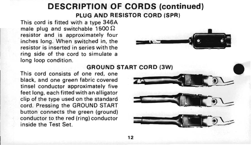
PLUG
AND RESISTOR CORD (SPR)
This cord is fitted with a type 346A
male plug and switchable
1500
fi
resistor and is approximately four
inches long. When switched in, the
resistor is inserted inseries withthe
ring side of the cord to simulate a
long loop condition.
-
GROUND START CORD
(3W)
This cord consists of one red, one
black, and one green fabric covered
tinsel conductor ap~roximatelvfive
feet long, eachfitted'with ana~l/~ator
clipof the type used onthe standard
cord. Pressina the GROUND START
button connects the green (ground)
conductor to the red(ring)conductor
inside the Test Set.
TCI Library: www.telephonecollectors.info

OPERATION
SIGNALING
entered at any rate on the keypad;
Place the TALK/MONITOR switch in digits will automatically be pulsed
the M position, and connect Test Set out at the correct rate. To terminate
to the line; verify that the line is idle.
Set the KEYPAD switch to IN. Select
the type of dial signaling required,
touch tone or rotary dial pulses, with
the MODE switch. Set the TALK/
MONITOR switch toT, andverify that
dialtone isreceived(whenfurnished).
Enter thedesired number tobecalled
onthe keypad. Iftouchtonesignaling
has been selected, the tones associ-
atedwitheach digitwillbegenerated
as its respective button is pressed. If
rotary dial pulse signaling has been
selected, the desired number maybe
thecall, either during or after dialing,
return the TALK/MONITOR switch
to the M position.
POLARITY
CHECK
Set the TALK/MONITOR switch to
M.Connecttest leadstocircuitunder
test; verify that circuit is idle. Press
and hold inthe POLARITY button. If
the red LED lights, the redtest leadis
connected to the tip
(+)
side and the
black test lead is connected to the
.ring
(-)
side; if the amber LED lights,
the red test lead is connected to the
TCI Library: www.telephonecollectors.info
ring
(-)
side and the black test lead is
connected to the tip
(+)
side:
CAUTION:
Operationof the PO-
LARITY button on a busycircuit may
cause annoying clicks or service in-
terruptions. Operation of this switch
on an idle circuit may cause line
seizure.
LINE MONITORING
Set the TALK/MONITOR switch toM
(KEYPAD and MODE switches may
be in either position), and connect
test leadstocircuit under test. Moni-
toring may nowbe done without dis-
rupting traffic.
OPERATION ON LOW VOLTAGE
OR DRY CIRCUITS
Set KEYPAD switch to OUT and
TALK/MONITOR switch to M. Con-
nect test leads to circuit under test;
verify that circuit is idle. Set the
TALK/MONITOR switchtoTfor two-
way communications.
Setting the KEYPAD switch to OUT
bypasses the Test Set electronics,
thereby increasing its loop limit.The
Test Set signaling function will not
operate in this mode, but all other
functions operate normally.
TCI Library: www.telephonecollectors.info

GROUND START LINE SEIZURE
connectstogether theground(green)
(optional)
and ring (red) leads of the three-
Pressing the GROUNDSTARTbutton conductor test cord.
TROUBLESHOOTING PROCEDURES
The following troubleshooting
procedures are based largely on the
CLICK that will be heard when the
two TS21 test leads are placed on
battery and ground respectively, or
across a charged capacitor.
These CLICKSandother soundsfrom
the receiver can greatly assist a
skilled craftsperson in locating open
circuits, shorts, crosses, andgrounds.
1.
To locate a short circuit, open
one side of the line and place the
TS21 in the loop-one test lead to
each side of the opened line. On the
C.O. side of the fault, a loud CLICK
will be heard; onthe field side of the
fault, NO CLICK will be heard.
2. Locating an open circuit is
accomplished by bridging the TS21
across the circuit-one test lead on
TCI Library: www.telephonecollectors.info
tip, the other on ring. Moving away
from the C.O., the fault is located at
the point the CLICK disappears.
3. Continuity of each side of the
loop may be verified by placingoneof
the test leads on a local ground and
the other on the conductor in ques-
tion. On a good RING conductor, a
CLICK will be heard; on a good TIP
conductor, an inductive HUMwill be
heard(duetothedifferenceinground
potential between the C.O. ground
and the local ground).
For a full discussion on these
troubleshooting procedures, you are
referred to your company's practices
or to "Lee's ABC of the Telephone",
Vol. 2, Chapters 13, 14, and 15.
CAUTION: Whentesting circuits
which are relatively close tothe bat-
tery source, theCLICKS inthereceiver
may be loudenough to causeacous-
tical shock if the receiver is held
tightly against the ear. The TS21 is
designed to rest comfortably on the
shoulder withthereceiver awayfrom
theear. Itshouldbe used inthisposi-
tion when listening for CLICKS.
TCI Library: www.telephonecollectors.info

WARRANTY:
Dracon guarantees equipment of its manufactureandeach part
or component thereof against all defects inmaterial and/or workmanship and
agreesto remedy any such defect at nochargeprovidedthatthedefective unitis
returnedtransportation prepaidtothe Draconfactoryfromwhichshipmentwas
made.This warranty extendsforaperiodof one year fromthedateof installation
or initialuse, providedthat this periodshall not exceed
18
monthsfromthedate
of shipment from factory. In no event will Dracon be liablefor any incidental or
consequential damages.
This warranty does not extend to products which have been subjected to
neglect, accident or improper use, norto unitswhich havebeenalteredbyother
than authorized Dracon personnel.
RETURN
OF
EQUIPMENT:
To return Test Set to Dracon, first obtaina Return
Authorization Number from a Dracon Representative. This number must be
clearly marked on shipping container or container will not be accepted by
Dracon.
TCI Library: www.telephonecollectors.info

809
CALLE
PLAN0
CAMARILLO
CALIFORNIA
93010
TCI Library: www.telephonecollectors.info
This manual suits for next models
7
Table of contents
Other Harris Test Equipment manuals


Popular Test Equipment manuals by other brands


Extech Instruments
Extech Instruments ET20B user manual

Rohde & Schwarz
Rohde & Schwarz RTM2032 user manual

GE
GE Druck DPI 620 user manual

MULTI MEASURING INSTRUMENTS CO.,LTD.
MULTI MEASURING INSTRUMENTS CO.,LTD. MIS-2D instruction manual

EXFO
EXFO IQS-12001B Brochure & specs

Kenwood
Kenwood CS-6020 instruction manual