RS 215-6391 Manual

Issued / Herausgegeben / Publicado / Publicatto 09/2001 V10515
Shielded tester II 215-6391
Adaptor lead/coupler 450-758
This RS data wiring tester is used to verify or indicate wiring errors on
2, 3 and 4 pair voice and data channels. The continually sequencing
LED display provides instant indication of any shorts, open, reversals
and miswires.
The master and remote units separate for end-to-end testing of
installed cabling. Use the tester to check each channel back to the main
distribution frame, verify cross connections, and test all line cords.
Troubleshooting
Main frame to test point
If there are a large number of tests to be performed or if the tests
involve substantial distances, we recommend using two people and
radio/telephone communication.
In order to protect the sockets in the tester, we recommend that adaptor
lead (RS stock no. 450-758) be plugged into the tester and that the lead
be used to connect and disconnect to/from the channel under test. This
will reduce wear on the tester contact set and ensure long term, reliable
operation. An RJ45 socket to socket coupler is included with RS stock
no. 450-758 so that the tester can test both socket and plug terminated
channels.
1. Select the proper sockets on the tester for the wiring
scheme to be tested.
2. Attach the remote unit at the test point.
3. Attach the master unit at the main distribution frame.
4. Read the LED's as follow:
Chart 1
For USOC, 568A and 568B.
Chart 2
The tester will check pairs according to the following chart:
Shielded testing
In addition to the standard troubleshooting facilities, the shielded tester
will verify the integrity of shielded twisted pair cables (STP).
It is advisable to use shielded lead (RS stock no. 365-9043) for
connection between the tester and channel sockets.
1. Connect the remote and master units to local outlet and main panel
respectively.
2. With the master shield switch in the OFF position, verify pair
continuity using Chart 1 on this sheet.
3. With master shield switch set to TEST position, verify shield
continuity as follows:
4. On remote unit, hold shield switch in BRK position and verify that
GREEN OK LEDs on BOTH units go off.
Battery replacement
Fit the battery in the master unit.
1. Remove the screws from the back of the master unit with a
size 'O' Phillips screwdriver. Set screws aside.
2. Remove and replace the 9V PP3 alkaline battery with a similar one
, e.g. RS stock no. 394-9059.
3. Replace the cover and screws, being careful not to
overtighten the screws.
WARNING: Do not use on MAINS or LIVE circuits.
RS Components shall not be liable for any liability or loss of any nature (howsoever
caused and whether or not due to RS Components’ negligence) which may result
from the use of any information provided in RS technical literature.
Master Remote
Green 1 and OK LEDs ON Green OK LED ON
USOC
6 Wire 8 Wire 568A 568B
4 5 5 5 Pair 1 (No. 1 LED)
3 4 4 4
2 3 3 1 Pair 2 (No. 2 LED)
5 6 6 2
1 2 1 3 Pair 3 (No.3 LED)
6 7 2 6
8 7 7 Pair 4 (No. 4 LED)
1 8 8
Master Remote Diagnosis
LED on (green) LED on (green) Good channel
LED on (green) LED on (red) Reversal
LED on (green) LED off Short within pair
2 LEDs on (green) 2 LEDs on Short between pairs
LED off LED off Open
LED out of LED out of Transposed pairs
sequence sequence
RS Stock No.
Data Wiring Tester
Prüfgerät für Datenverkabelungen
Comprobador del cableado de datos
Analizzatore per cablaggi dati
Instruction Leaflet
Bedienungsanleitung
Hojas de instrucciones
Foglio d’instruzioni

2
215-6391 Geschirmtes Prüfgerät II
450-758 Adapterleitung/Kupplungsstück
Dieses RS Prüfgerät für Datenverkabelungen dient zur Überprüfung
von zwei-, drei- und vierpaarigen Sprach- und Datenkanälen und zur
Anzeige von Verkabelungsfehlern. Die kontinuierliche LED-
Sequenzanzeige gibt sofort Aufschluss über Kurzschlüsse, offene
Anschlüsse, verpolte und falsch angeschlossene Leitungen.
Die Basis- und Fernstationen lassen sich unabhängig voneinander
einsetzen, um eine durchgängige Überprüfung der installierten
Verkabelung zu ermöglichen. Sie können das Prüfgerät verwenden, um
jeden Kanal bis zum Hauptleitungsverteiler zurückzuverfolgen,
Querverbindungen zu überprüfen und alle Leitungskabel zu testen.
Fehlersuche
Verbindung vom Hauptleitungsverteiler zum Prüfpunkt
Falls Sie eine große Zahl von Tests vornehmen möchten oder falls die
Tests über erhebliche Entfernungen durchgeführt werden sollen, ist es
empfehlenswert, eine weitere Person hinzuzuziehen, mit der Sie über
eine Funk- oder Telefonverbindung Kontakt aufnehmen können.
Damit die Anschlussbuchsen des Prüfgeräts geschützt werden, wird
empfohlen, dieAdapterleitung (RS Best.-Nr. 450-758) an das Prüfgerät
anzuschließen und die Verbindung mit dem zu überprüfenden Kanal
dann über dieseAdapterleitung herzustellen und zu trennen. Auf diese
Weise verringern Sie den Verschleiß am Kontaktsatz des Prüfgeräts
und stellen einen langen und zuverlässigen Betrieb des Prüfgeräts
sicher. Zur Adapterleitung (RS Best.-Nr. 450-758) gehört auch ein
Kupplungsstück von RJ45-Buchse auf RJ45-Buchse, sodass Sie mit
diesem Prüfgerät Kanäle überprüfen können, die mit Buchsen und
Steckern terminiert sind.
1. Wählen Sie am Prüfgerät die richtige Buchse für das
Verdrahtungsschema, das überprüft werden soll.
2. Schließen Sie die Fernstation an den Prüfpunkt an.
3. Schließen Sie die Basisstation an den Hauptleitungsverteiler an.
4. Lesen Sie die Diagnoseinformationen an den LEDs ab (siehe
folgende Tabelle).
Tabelle 1
Verkabelungen nach USOC, 568A und 568B
Tabelle 2
Sie können mit dem Prüfgerät Paare nach den Angaben in der
folgenden Tabelle überprüfen:
Geschirmte Prüfung
Neben den Standardmöglichkeiten zur Fehlersuche bietet Ihnen das
geschirmte Prüfgerät auch die Möglichkeit, die Integrität von STP-
Kabeln (geschirmten verdrillten Paaren) zu überprüfen.
Bei solchen Prüfungen ist es jedoch empfehlenswert, ein geschirmtes
Anschlusskabel (RS Best.-Nr. 365-9043) für die Verbindung zwischen
dem Prüfgerät und den Kanalbuchsen zu verwenden.
1. Schließen Sie die Fernstation und die Basisstation an den lokalen
Auslass bzw. an den Hauptleitungsverteiler an.
2. Bringen Sie den Schirmungsschalter der Basisstation in die Stellung
OFF (Aus) und überprüfen Sie dann die Durchgängigkeit des Paars
entsprechend den Angaben in Tabelle 1.
3. Bringen Sie den Schirmungsschalter der Basisstation in die Stellung
TEST und überprüfen Sie dann die Durchgängigkeit der Schirmung
auf folgende Weise:
4. Halten Sie den Schirmungsschalter der Fernstation in der Stellung
BRK und überzeugen Sie sich, dass die grüne LED OK an beiden
Stationen erlischt.
Batteriewechsel
Legen Sie die Batterie folgendermaßen in die Basisstation ein:
1. Entfernen Sie die Schrauben der Batterieabdeckung auf der
Rückseite der Basisstation mit einem Kreuzschlitzschraubendreher
der Größe "O". Legen Sie die Schrauben zur Seite.
2. Entfernen Sie die alte 9V-Alkalibatterie des Typs PP3 (E-Block) und
legen Sie eine neue Batterie des gleichen Typs ein - z.B. RS Best.-
Nr. 394-9059.
3. Setzen Sie die Batterieabdeckung wieder ein und ziehen Sie die
Schrauben wieder fest. Achten Sie dabei darauf, dass Sie die
Schrauben nicht zu fest anziehen.
Vorsicht! Verwenden Sie dieses Prüfgerät keinesfalls für Prüfungen
im NETZ oder an STROMFÜHRENDEN Schaltungen.
RS Components haftet nicht für Verbindlichkeiten oder Schäden jedweder Art (ob auf
Fahrlässigkeit von RS Components zurückzuführen oder nicht), die sich aus der
Nutzung irgendwelcher der in den technischen Veröffentlichungen von RS
enthaltenen Informationen ergeben.
Basisstation Fernstation
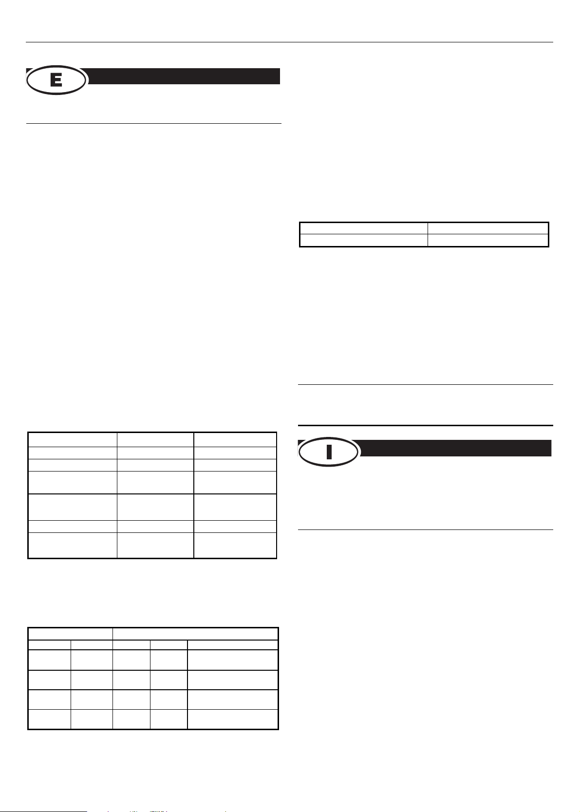
Grüne LED Nr. 1 und LED OK leuchten Grüne LED OK leuchtet
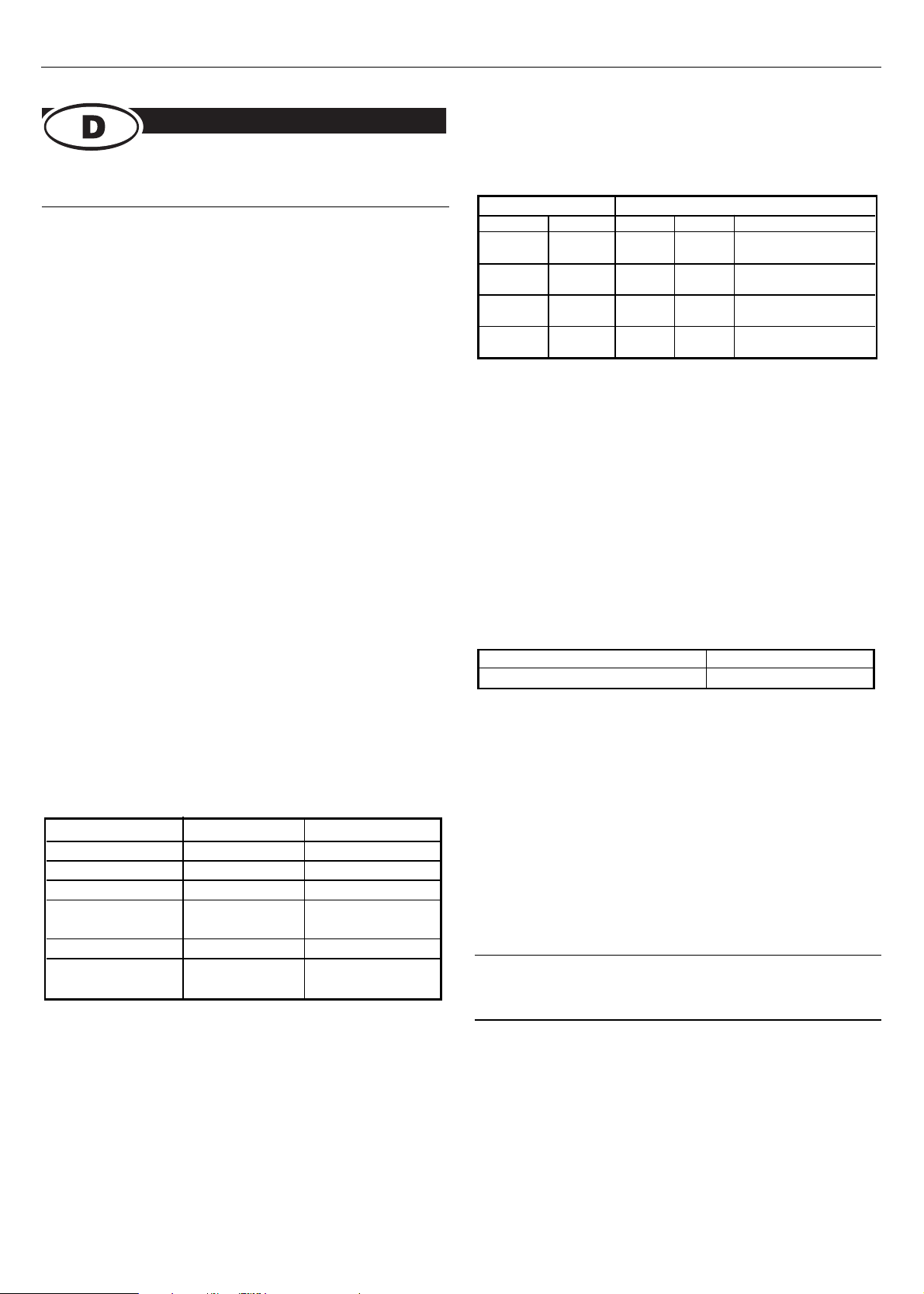
USOC
6-Draht 8-Draht 568A 568B
4 5 5 5 Paar 1 (LED Nr. 1)
3 4 4 4
2 3 3 1 Paar 2 (LED Nr. 2)
5 6 6 2
1 2 1 3 Paar 3 (LED Nr. 3)
6 7 2 6
8 7 7 Paar 4 (LED Nr. 4)
1 8 8
Basisstation Fernstation Diagnose
LED leuchtet (grün) LED leuchtet (grün) Einwandfreier Kanal
LED leuchtet (grün) LED leuchtet (rot) Verpolung
LED leuchtet (grün) LED leuchtet nicht Kurzschluss im Paar
2 LEDs leuchten (grün) 2 LEDs leuchten Kurzschluss zwischen
Paaren
LED leuchtet nicht LED leuchtet nicht Offener Anschluss
LED nicht in Sequenz LED nicht in Sequenz Vertauschte
Paare
RS Best-Nr.
V10515

3
215-6391 yComprobador apantallado II
450-758 Adaptador toma/acoplador
Este comprobador de cableado de datos de RS se utiliza para verificar
o indicar los errores de cableado en 2, 3 y 4 pares de canales de voz
y datos. El LED de secuencia continua indica instantáneamente
cualquier puente, cableado abierto, inverso y defectuoso.
Las unidades maestra y remota se separan para la verificación de
extremo a extremo del cableado instalado. Utilice el comprobador para
chequear que cada canal vuelve al cuadro de distribución principal,
verificar las conexiones cruzadas y comprobar toda la línea de cables.
Resolución de problemas
Cuadro principal para comprobar la punta
Si el número de pruebas a realizar es grande o si las pruebas implican
distancias considerables, recomendamos la colaboración entre dos
personas utilizando comunicación por radio/teléfono.
Para proteger los zócalos del comprobador se recomienda enchufar el
cable adaptador (Código RS 450-758) al comprobador y utilizar el
adaptador para conectar y desconectar el canal en prueba. Con ello,
se reduce el desgaste en el conjunto de contacto del comprobador y
se garantiza un funcionamiento fiable. Se incluye un zócalo RJ45 para
que el comprobador pueda chequear los canales que terminan en
zócalo y los que terminan en enchufe.
1. Seleccione en el comprobador los zócalos apropiados para
el esquema de cableado que se ha de comprobar.
2. Junte la unidad remota al punto de prueba.
3. Junte la unidad maestra al cuadro de distribución principal.
4. La lectura de los LED es la siguiente:
Cuadro 1
Para USOC, 568A y 568B
Cuadro 2
El comprobador verificará los pares de acuerdo con el cuadro
siguiente:
Comprobación apantallada
Además de la facilidad de resolución de problemas estándar, el
comprobador apantallado verificará la integridad de los cables de
pares trenzados apantallados (STP).
Se recomienda utilizar un cable apantallado (Código RS: 365-9043)
para realizar las conexiones entre el comprobador y los zócalos del
canal.
1. Conecte las unidades remota y maestra a una toma local y
al panel principal respectivamente.
2. Con el interruptor apantallado maestro en la posición OFF,
compruebe la continuidad del par utilizando el Cuadro 1 de
esta hoja.
3. Con el interruptor apantallado maestro en la posición TEST,
compruebe la continuidad del par de la manera siguiente:
4. En la unidad remota, mantenga el interruptor apantallado
en la posición BRK y compruebe que los LED VERDE y OK
de AMBAS unidades se desactivan.
Sustitución de las baterías
Coloque la batería en la unidad maestra.
1. Retire los tornillos de la parte trasera de la unidad maestra
con un destornillador Phillips de tamaño ´O´. Sitúe los
tornillos aparte.
2. Retire y sustituya las baterías alcalinas PP3 de 9V por unas
similares, por ejemplo, las Código RS: 394-9059.
3. Coloque de nuevo la cubierta y los tornillos, prestando
atención para no apretar demasiado los tornillos.
ADVERTENCIA: No lo utilice en circuitos CON CORRIENTE o
en REDES ELÉCTRICAS.
RS Components no será responsable de ningún daño o responsabilidad de cualquier
naturaleza (cualquiera que fuese su causa y tanto si hubiese mediado negligencia de
RS Componentscomo si no) que pudiese derivar del uso de cualquier información
incluida en la documentación técnica de RS.
215-6391
Analizzatore schermato II
450-758
Cavo/accoppiatore dell’adattatore
Questo analizzatore per cablaggio dati RS è utilizzato per
verificare o indicare gli errori di cablaggio su canali dati/fonia a 2, 3
e 4 paia. Il display LED a sequenza continua segnala
tempestivamente cortocircuiti, circuiti aperti, inversioni e cablaggi
errati.
Le unità master e remota sono separate per permettere l’analisi end-
to-end dei cavi installati. L’analizzatore può essere utilizzato per
controllare ogni canale fino al quadro di distribuzione, verificare i
collegamenti incrociati e analizzare tutti i cavi di linea.
Risoluzione dei problemi
Dal quadro principale al punto di prova
Se occorre eseguire molti test, oppure il test presuppone distanze
notevoli, è consigliabile che l’apparecchiatura sia usata da due persone
in contatto via radio/telefono.
Per proteggere le prese dell’analizzatore, il cavo dell’adattatore (codice
450-758) dovrebbe essere inserito nell’analizzatore e usato per
collegare e scollegare il canale in fase di analisi. In questo modo si
riduce l’usura dei contatti dell’analizzatore garantendo una maggiore
affidabilità a lungo termine dell’apparecchiatura. Il codice 450-758 è
fornito con accoppiatore da presa a presa RJ45 e può essere pertanto
utilizzato anche per l’analisi di canali con terminazione a presa e a
spina.
RS Codici.
Maestro Remoto
LED Verde 1 y OK en ON (activos) LED Verde y OK en ON (activos)
USOC
Cable 6 Cable 8 568A 568B
4 5 5 5 Par 1 (1 LED)
3 4 4 4
2 3 3 1 Par 2 (2 LED)
5 6 6 2
1 2 1 3 Par 3 (3 LED)
6 7 2 6
8 7 7 Par 4 (4 LED)
1 8 8
Maestro Remoto Diagnóstico
LED activo (verde) LED activo (verde) Canal bueno
LED activo (verde) LED activo (rojo) Invertido
LED activo (verde) LED desactivado Puente dentro del
par
2. LED activos (verde) 2. LED activos Puente entre
pares
LED desactivado LED desactivado Abierto
LED fuera de LED fuera de Pares
secuencia secuencia transpuestos
Código RS.
V10515

1. Selezionare sull’analizzatore le prese adatte agli schemi di
cablaggio da analizzare.
2. Collegare l’unità remota al punto di prova.
3. Collegare l’unità master al quadro di distribuzione principale.
4. Leggere i LED come segue:
Schema 1
Per USOC, 568A e 568B.
Schema 2
L’analizzatore controlla le paia in base allo schema seguente:
Controllo con schermatura
Oltre alle funzionalità di risoluzione dei problemi standard,
l’analizzatore schermato verifica l’integrità dei cavi twisted pair
schermati (STP).
Per il collegamento tra l’analizzatore e le prese del canale, è
consigliabile utilizzare il cavo schermato (codice 365-9043).
1. Collegare le unità remota e master rispettivamente alla presa locale
e al pannello principale.
2. Con l’interruttore master schermato in posizione OFF, verificare la
continuità del paio utilizzando lo Schema 1.
3. Con l’interruttore master schermato in posizione TEST, verificare la
continuità della schermatura come segue:
4. Sull’unità remota, tenere l’interruttore schermato in posizione BRK
e verificare che i LED VERDI OK su ENTRAMBE le unità siano
spenti.
Sostituzione della batteria
Installare la batteria nell’unità master.
1. Rimuovere le viti sul retro dell’unità master utilizzando un cacciavite
Phillips di dimensione 'O'. Riporre le viti.
2. Rimuovere e sostituire la batteria alcalina da 9V PP3 con una
simile, ad esempio codice 394-9059.
3. Installare nuovamente il coperchio e le viti, facendo attenzione a
non serrarle troppo.
Attenzione: Non utilizzare su circuiti DI RETE ELETTRICA o SOTTO
TENSIONE.
La RS Components non si assume alcuna responsabilità in merito a perdite di
qualsiasi natura (di qualunque causa e indipendentemente dal fatto che siano dovute
alla negligenza della RS Components), che possono risultare dall’uso delle
informazioni fornite nella documentazione tecnica.
Master Remoto
LED verde 1 e OK ACCESI LED verde OK ACCESO
USOC
6 cavi 8 cavi 568A 568B
4 5 5 5
Paio 1 (LED n. 1)
3 4 4 4
2 3 3 1
Paio 2 (LED n. 2)
5 6 6 2
1213
Paio 3 (LED n. 3)
6726
8 7 7
Paio 4 (LED n. 4)
1 8 8
Master Remoto Diagnosi
LED acceso (verde) LED acceso (verde) Canale senza problemi
LED acceso (verde) LED acceso (rosso) Inversione
LED acceso (verde) LED spento Cortocircuito nel paio
2 LED accesi (verde) 2 LED accesi Cortocircuito tra un
paio e l’altro
LED spento LED spento Circuito aperto
LED fuori LED fuori Paia trasposte
sequenza sequenza
V10515
Table of contents
Languages:
Other RS Test Equipment manuals