Teradyne Z1890 Manual

Artisan Technology Group is your source for quality
new and certied-used/pre-owned equipment
• FAST SHIPPING AND
DELIVERY
• TENS OF THOUSANDS OF
IN-STOCK ITEMS
• EQUIPMENT DEMOS
• HUNDREDS OF
MANUFACTURERS
SUPPORTED
• LEASING/MONTHLY
RENTALS
• ITAR CERTIFIED
SECURE ASSET SOLUTIONS
SERVICE CENTER REPAIRS
Experienced engineers and technicians on staff
at our full-service, in-house repair center
WE BUY USED EQUIPMENT
Sell your excess, underutilized, and idle used equipment
We also offer credit for buy-backs and trade-ins
www.artisantg.com/WeBuyEquipment
REMOTE INSPECTION
Remotely inspect equipment before purchasing with
our interactive website at www.instraview.com
LOOKING FOR MORE INFORMATION?
Visit us on the web at www.artisantg.com for more
information on price quotations, drivers, technical
specications, manuals, and documentation
Contact us: (888) 88-SOURCE | sales@artisantg.com | www.artisantg.com
SM
View
Instra

Z1800-Series
Teradyne, Inc.
Assembly Test/Walnut Creek
2625 Shadelands Drive
●
Walnut Creek, CA 94598-2597
Publication Number 1800M009 Copyright Teradyne, Inc.
OPERATOR’S
GUIDE

Product Warranty
THE STANDARDTERADYNE WARRANTY CONSTITUTES THE ONLY REPRESENTATION OR
WARRANTY MADE BY TERADYNE WITH RESPECTTO ANY EQUIPMENT, GOODS OR SERVICES
SUPPLIED BY TERADYNE. TERADYNE MAKES NO OTHER WARRANTIES OR
REPRESENTATIONS, EXPRESSED OR IMPLIED, IN FACT OR IN LAW, INCLUDING THE IMPLIED
WARRANTIES OF MERCHANTABILITY AND FITNESS FOR A PARTICULAR PURPOSE. IN NO
EVENT WILL TERADYNE BE LIABLE FOR INCIDENTAL, SPECIAL OR CONSEQUENTIAL
PENALTIES OR DAMAGES, INCLUDING LOST PROFITS, OR PENALTIES AND/OR DAMAGES FOR
DELAY IN DELIVERY OR FAILURE TO GIVE NOTICE OF DELAY, EVEN IF TERADYNE HAS BEEN
ADVISED OF THE POSSIBILITY OF SUCH DAMAGES.
Due to an ongoing policy of constantly updating equipment and procedures, the contents of this
document are subject to change without notice.
Teradyne assumes no responsibility for errors or for any damages that result from the implementation of
the procedures described in this publication. Teradyne also reserves the right to make changes in its
products without incurring any obligation to incorporate such changes in units previously sold or
shipped. Teradyne makes no commitment to update nor to keep current the information contained in
this document.
Teradyne assumes no responsibility for the use of any circuitry other than the circuitry embodied as a
Teradyne product. No other circuit patent licenses are implied.
This software system consists of computer software and documentation.It contains trade secrets and
confidential information which are proprietary to Teradyne, Inc. Its use or disclosure in whole or in part
without the express written permission of Teradyne, Inc.is prohibited.
This software system is also an unpublished work protected under the copyright laws of the United
States of America. If this work becomes published, the following notice shall apply:
Copyright © 1998 Teradyne, Inc. All Rights Reserved.
Trademarks
The following are trademarks or registered trademarks of Teradyne and may be used to describe only
Teradyne, Inc., Assembly Test/Walnut Creek products:
Borland and Paradox are trademarks of Borland International, Inc.
C++ and UNIX are registered trademarks of AT&T Bell Laboratory.
Codewright is a trademark of Premia Corporation.
ETHERNET is a trademark of Xerox Corporation.
FABmaster is a registered trademark of FABMASTER S.A.
HP-UX is a registered trademark of Hewlett-Packard Company.
IBM, MicroChannel, and PS/2 are registered trademarks of International Business Machines, Inc.
LabWindows, LabWindows/CVI, NI-488.2, and NI-VXI are trademarks of National Instruments
Corporation.
Microsoft, MS-DOS, QuickC, Windows 95, and WindowsNT are either registered trademarks or
trademarks of Microsoft Corporation in the United States and/or other countries.
Okidata and Microline are registered trademarks of Oki Electric Industry Company, Ltd.
OS-9 and Microware are registered trademarks of Microware Systems Corporation.
SunOS and Solaris are registered trademarks of Sun Microsystems, Inc.
VAX and VMS are registered trademarks of Digital Corporation.
APC
AutoLoad
AutoLocate
BoardWatch
Boundary Scan Intelligent
Diagnostics (BSID)
CapScan
Component Designer (CDES)
DeltaScan
FrameScan
FrameScan Plus
HostLink
Inline Device Programmer
(ILDP)
InterScan
MultiScan II
PentaVision
PRISM
ProcessWatch
Programmer Efficiency
Package (PEP)
Quick-Check
Safecracker
Spectrum 8800-Series
Test Toolbox
Tester-Aided Instruction
TestQA
VICTORY
VP/VXI
WaveScan
Z1800-Series

Z1800-S
ERIES
O
PERATOR
’
S
G
UIDE
Manual History
•
Nineth Edition, October 1998, F.2b operating system
•
Eighth Edition, June 1996, F.1 operating system
•
Seventh Edition, October 1995, F.0 operating system
•
Sixth Edition, June 1995, Version E.4 operating system
•
Fifth Edition, January 1994, Version E.0 operating system
•
Fourth Edition, December 1992, Version D.2 operating system
•
Third Edition, February 1992, Version D.1 operating system
•
Preliminary Second Edition, November 1991, Version D.0 operating system
•
First Edition, July 1991, Version C.1 operating system
Additional copies of this manual may be obtained from Teradyne.
Publications No. 1800M009
© 1992, 1994, 1995, 1996, 1998 Teradyne Inc.,Assembly Test/Walnut Creek
2625 Shadelands Drive .Walnut Creek, CA 94598 .(925) 932-6900
Customer Service Hotline (800) 457-8326


C
ONTENTS
Preface
Chapter 1 Safety
Teradyne’s Product Safety Policy....................................................... 1-1
General Safety Information................................................................. 1-1
Safety Practices.................................................................................. 1-2
Operation ...................................................................................... 1-2
Electrostatic Discharge ................................................................. 1-3
Safety Symbols and Markings............................................................. 1-4
Safety Symbols ............................................................................. 1-4
Safety Labels ................................................................................ 1-4
Warning Terminology.................................................................... 1-5
Power On/Off Sequence..................................................................... 1-5
Power On ...................................................................................... 1-5
Normal Power Off.......................................................................... 1-6
Emergency Power Off......................................................................... 1-9
Emergency Manual Off Switch...................................................... 1-9
External Hazards................................................................................. 1-9
Electrical........................................................................................ 1-9
Mechanical.................................................................................... 1-9
Safety Notes...................................................................................... 1-10
Z1890, Z1880.............................................................................. 1-10
Z1888—Z1888-1, Z1888-2.......................................................... 1-12
Z1884.......................................................................................... 1-15
Z1866.......................................................................................... 1-18
Z1860-NB.................................................................................... 1-20
Z1860.......................................................................................... 1-22
Z1850.......................................................................................... 1-24
Z1840.......................................................................................... 1-26
Z1820.......................................................................................... 1-28
Z1808, Z1805.............................................................................. 1-30
Z1803 Plus—Z1803-1, Z1803-2.................................................. 1-32
Z1800.......................................................................................... 1-34
Z1860M....................................................................................... 1-37
Z1850M....................................................................................... 1-39
Z1840M....................................................................................... 1-41

II
Chapter 2 Tester Description
Illustrations of the Testers................................................................... 2-1
Z1890, Z1880................................................................................ 2-2
Z1888—Z1888-1, Z1888-2............................................................ 2-3
Z1884............................................................................................ 2-4
Z1866............................................................................................ 2-5
Z1860-NB...................................................................................... 2-6
Z1860............................................................................................ 2-7
Z1850............................................................................................ 2-8
Z1840............................................................................................ 2-9
Z1820.......................................................................................... 2-10
Z1808, Z1805.............................................................................. 2-11
Z1803 Plus—Z1803-1, Z1803-2.................................................. 2-12
Z1800.......................................................................................... 2-13
Z1860M....................................................................................... 2-14
Z1850M....................................................................................... 2-15
Z1840M....................................................................................... 2-16
Console Controls......................................................................... 2-17
Operator Control Panels ............................................................. 2-17
Operator Control Pod.................................................................. 2-20
Emergency Manual Off Switch.................................................... 2-20
Test Jack Panels......................................................................... 2-21
Interface Vacuum Switches......................................................... 2-24
Rear Panels ...................................................................................... 2-26
Rear Panels—Z1890, Z1888, Z1880, Z1808,
Z1805, Z1803 Plus...................................................................... 2-26
Rear Panel—Z1884, Z1860-NB, Z1860, Z1840, Z1866, Z1850 . 2-27
Rear Panels—Z1820, Z1800 ...................................................... 2-28
Rear Panel—Z1860M, Z1840M, Z1850M................................... 2-29
AC Power System............................................................................. 2-29
AC Power Distribution Assembly—Z1890, Z1888,
Z1880, Z1860-NB, Z1808, Z1805, Z1803................................... 2-30
AC Power Distribution Assembly—Z1884................................... 2-31
AC Power Distribution Assembly—Z1866, Z1860, Z1850,
Z1840,Z1860M, Z1850M, Z1840M ............................................. 2-32
Fixture Receiver Interface................................................................. 2-33
Fixture Receiver Interface—Z1890, Z1888, Z1880,
Z1808, Z1805, Z1803 Plus.......................................................... 2-33
Fixture Receiver Interface—Z1884 ............................................. 2-34
Fixture Receiver Interface—Z1866 ............................................. 2-35

III
Z1800-Series Operator’s Guide
Fixture Receiver Interface—Z1860-NB, Z1860........................... 2-36
Fixture Receiver Interface—Z1850 ............................................. 2-37
Fixture Receiver Interface—Z1840 ............................................. 2-37
Fixture Receiver Interface—Z1860M, Z1850M, Z1840M............ 2-37
Fixture Receiver Interface—Z1820 ............................................. 2-38
Fixture Receiver Interface—Z1800 ............................................. 2-38
Vacuum System—Vacuum Testers.................................................. 2-39
Fixture—Vacuum Testers ................................................................. 2-39
Computer .......................................................................................... 2-39
Keyboard..................................................................................... 2-39
Mouse ......................................................................................... 2-39
Screen Color ............................................................................... 2-39
Printer.......................................................................................... 2-39
Chapter 3 Operating the Tester
Daily Operations.................................................................................. 3-2
Set Up for Static Safety................................................................. 3-2
Check the Printer .......................................................................... 3-3
Inspect the Fixture......................................................................... 3-3
Board Testing...................................................................................... 3-4
Load the Fixture and Board........................................................... 3-4
Log In ............................................................................................ 3-5
Test Boards................................................................................... 3-6
Testing Digital Connectivity............................................................... 3-11
Analyzing Printout of Test Results.................................................... 3-17
Component Failure Message...................................................... 3-17
AutoProbeCheck Failure Messages............................................ 3-18
Section Abort Messages ............................................................. 3-19
Shorts Locator Messages ........................................................... 3-19
Troubleshooting for Operators.......................................................... 3-20
Tester Power............................................................................... 3-20
Inconsistent Board Failures......................................................... 3-20
Failing Batches of Boards ........................................................... 3-20
Run Command............................................................................ 3-21
Vacuum Tester Problems............................................................ 3-21
Index

IV

V
Z1800-Series Operator’s Guide
P
REFACE
The
Z1800-Series Operator’s Guide
provides the information you need to operate Z1800-
series testers. The procedures outlined here are meant to be performed by persons
designated as operators.
This manual provides operator safety information, a description of tester hardware, and
instructions for operating the tester and interpreting test results.
Procedures requiring the expertise of technicians, programmers, or supervisors are
documented in your tester-specific system reference, the
Z1800-Series Maintenance
Reference, Z1800-Series Programmer’s Guidebook
, and the
Z1800-Series options
documentation pertinent to your system.
For detailed information about the documentation set, refer to the
Getting Started Quick
Reference.
How to Use the
Manual
To find information efficiently, refer to the table of contents and the index. The table of
contents lists first- and second-level headings and also lists the titles of illustrations and
tables. The index will help you find specific information in greater detail, often under
different terms reflecting varying ways of thinking about a topic.
To help you accomplish tasks, procedures are broken into numbered steps. Illustrations
accompanying procedures facilitate the performance of complex tasks.

VI

C
HAPTER
1 S
AFETY
The Z1800-Series test systems have been carefully designed for long-term safe and reliable
operation in a manufacturing environment. However, in-circuit testing requires that these
testers use and distribute high power and high voltage, both AC and DC. As a consequence,
if you do not follow proper tester operation procedures, the testers can cause serious
personal injury and equipment damage.
This chapter identifies tester hazards that operators may encounter. Read this chapter
before performing any operations on the tester.
Follow the precautions in this chapter during all stages of tester operation. Teradyne does
not assume liability for a customer’s failure to comply with established procedures.
Teradyne’s Product
Safety Policy
•
Teradyne equipment is designed and manufactured to be functionally safe for persons
who operate or service it. Potential hazards are addressed through a combination of
careful system design, appropriate warning labels, and documentation.
•
Teradyne equipment design reflects the Teradyne Product Safety Standards. These
standards incorporate applicable electrical codes and safety regulations. When codes
and regulations do not directly apply to automatic test equipment, the Teradyne Product
Safety Standards adhere to the spirit and purpose of these publications.
•
If specific questions arise about product safety or local requirements, Teradyne is
prepared to address these issues with any customer.
General Safety
Information
The tester is a “Safety Class 1” apparatus using a protective grounding scheme provided
from the protective ground wire of the “AC Mains” power cable.
WARNING!
Any interruption of the protective conductor inside or outside the apparatus or
disconnection of the protective earth terminal could possibly make the apparatus
dangerous. Intentional interruption is prohibited.
This apparatus has been designed and tested in accordance with
IEC Publication 348,
Safety Requirements for Electronic MeasuringApparatus
, and has been supplied in a
safe condition. The present instruction manual contains some information and warnings
which have to be followed by the user to ensure safe operation and to retain the apparatus
in safe condition.
The apparatus has been designed for indoor use. It may occasionally be subjected to
temperatures between -5
°
C and -10
°
C without degradation of its safety.
When the apparatus is connected to its power supply, terminals may be live, and the
opening of covers or removal of parts (except those to which access can be gained by hand)
is likely to expose live parts. The apparatus shall be disconnected from all voltage sources
before it is opened for any adjustment, replacement, maintenance, or repair.
Capacitors inside the apparatus may still be charged even if the apparatus has been
disconnected from all voltage sources.

1-2 SAFETY
Safety Practices
Safety features incorporated in the Z1800-Series testers are:
•
Safety warnings and information labels placed on testers close to hazards to warn a
knowledgeable service person of a potential hazard.
•
Detailed installation, verification, and service documentation.
•
Door locks to prevent unauthorized access to the interior of the testers.
Teradyne recommends that persons using the tester observe the safety practices described
below while the tester is operating.
WARNING!
The tester is capable of producing lethal voltages. Extreme care must be taken to
ensure the safety of persons operating the tester. Please read all safety information
before attempting operation.
Operation
Operators should read this manual and understand the procedures and precautions.
Teradyne does not assume liability for the customer’s failure to comply with established
procedures.
•
Consult your supervisor about the proper steps to take if the tester should experience an
operational problem.
•
Do not operate the tester in the vicinity of flammable gases or fumes.
•
Do not substitute parts or perform any unauthorized modifications to the tester, in order
to avoid introducing additional hazards.
•
Do not place tools, food, liquids, or any other items on the top surfaces of the tester.
•
Wear protective eyewear and nonflammable clothing.
•
Remove or cover conductive items such as rings and watches before using or servicing
the tester.
•
Exercise electrostatic discharge (ESD) control measures when handling components or
circuit assemblies. Refer to the section titled “Electrostatic Discharge.”
•
Do not replace components on a board-under-test when it is installed on the tester.
•
Be aware of and exercise caution against all electrical hazards which include:
•
DC voltages equal to or greater than 60V
•
AC voltages equal to or greater than 30Vrms (42 V peak)
•
24 V pulses
•
240 V-A power combination
•
10 joules reactive energy
•
Keep tester doors locked.
•
Use caution near the device-under-test when power is applied.Capacitors mounted in
reverse (reverse polarity) can explode.
•
Do not use water or any other unauthorized cleaning agent either externally or
internally.
•
Use caution when lifting large fixtures.
•
Do not work on the fixture while it is connected to the tester.
•
Do not remove fixture receiver covers while a program is running. Power may be
applied to the fixture receiver and consequently place the operator at risk.
•
If you have a vacuum tester, do not use the tester vacuum hose to clean any part of the
tester. Doing so clogs the vacuum and shortens the vacuum pump life.
•
Z1805, Z1808, Z1880 and Z1890 testers can be tilted up to 15 degrees or be raised up to
eight inches. Only qualified maintenance technicians should perform tilt adjustments.

1-3
Z1800-Series Operator’s Guide
•
Z1884 can be tilted up to 30 degrees with the powered tilt mechanism. Only qualified
maintenance technicians should perform tilt adjustments. The tester is intended to
operate in the tilted mode.
Electrostatic
Discharge
Manufacturers and users of electronic systems are becoming increasingly aware of the
impact which electrostatic discharge (ESD) can have on the operation and long term
reliability of complex equipment. This tester contains semiconductors which, by the nature
of their material or design, are susceptible to damage from ESD. The nature of ESD
damage may be either:
•
Hard failures, such as open or fused semiconductors, or
•
Partial failure caused by stressing device lands and junctions which degrades electrical
performance and increases failure susceptibility.
Teradyne offers the following recommendations to help prevent ESD damage.
Static Prevention
While operating the tester, use the operator’s wrist strap or another approved method of
preventing ESD. Connect the wrist strap to the wrist strap receptacle. Wrist strap
receptacles are located on the test jack panel of all testers and the rear (I/O) panels.
To minimize electronic charge generation:
•
Use ground straps whenever you are operating the tester.
•
Inform yourself about electrostatic charge phenomena, discharge damage, and methods
to prevent problems.
•
Eliminate offending insulating materials, such as the following, from work areas:
•
Plastic and styrofoam coffee cups
•
Food containers and wrappers
•
Clothing and shoes made from synthetic materials as well as rubber-soled shoes
•
Cellophane and paper tapes
•
Create a static conductive work area including static conducting floors and tables.
•
Properly ground both operators and boards to prevent ESD damage during unpacking,
installation, or removal of boards from the tester.
Static Control
To control electronic charge generation:
•
Drain static charges from persons and tools in the work area by using static conductive
floor mats and grounded antistatic service mats and using grounded wrist straps with 1
Megohm resistors.
•
When handing electronic devices or assemblies to another person, touch each other
before the exchange to neutralize static charges.
•
Minimize ESD damage by:
•
Moving and handling electronic parts and assemblies in antistatic containers.
•
Not touching printed circuit board lands or component leads of electronic
assemblies.
•
Servicing electronic assemblies in a static-controlled area.
•
Discharging static from tools before servicing electronic assemblies.
•Not using photocopies around the tester. Photocopies may carry electrostatic
charges.
1-4 SAFETY
Safety Symbols and
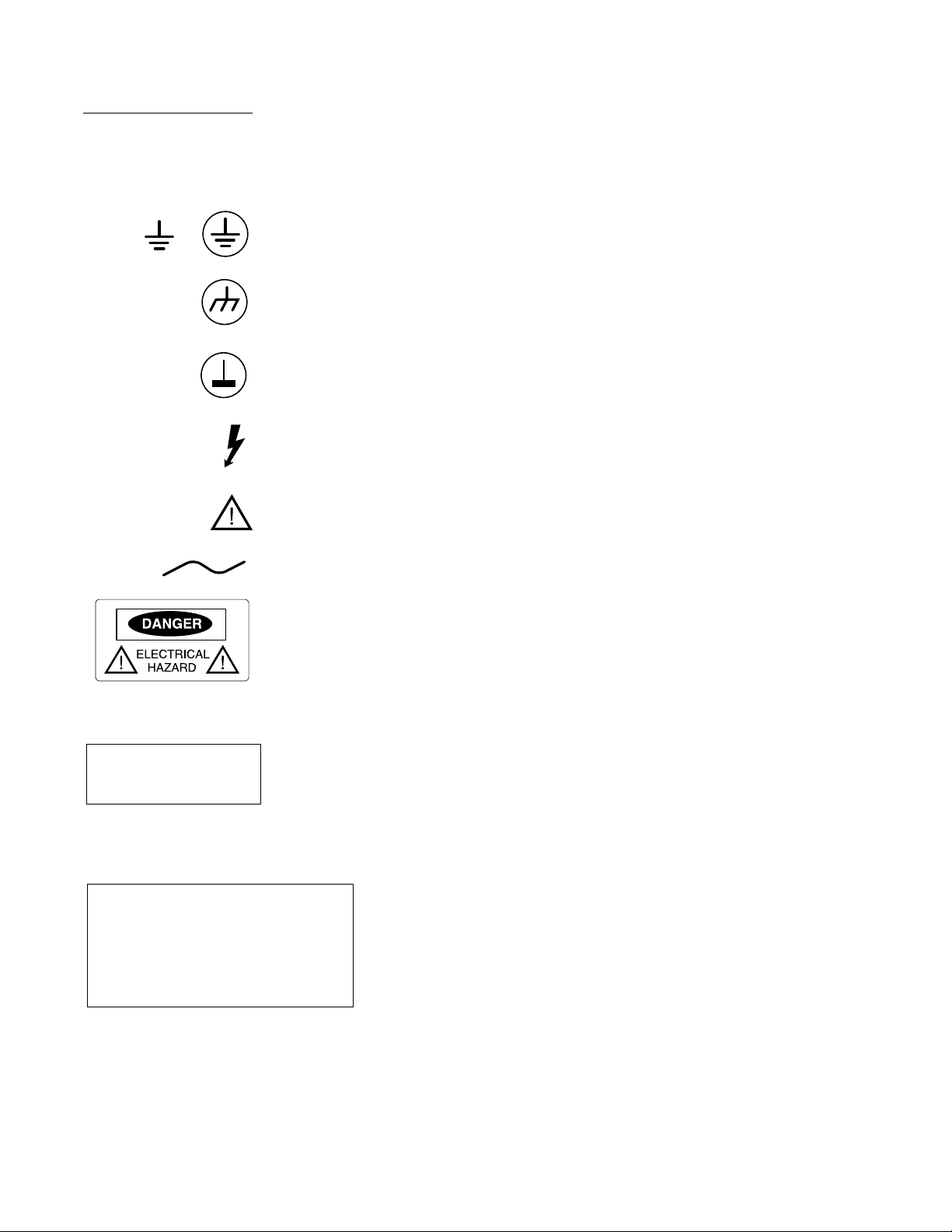
Markings The following symbols appear in various places on the tester to call your attention to
hazards or to indicate that you should consult the manuals for further information.
Safety Symbols
The protective ground symbol is used to define any connection point where a safety ground
wire is added to the hardware. This would normally be any conductive point referenced to
the safety ground wire of the main AC input.
The frame or chassis terminal symbol indicates a connection to the frame (chassis) of the
equipment which normally includes all exposed metal structures.
The remote instrumentation ground symbol indicates grounding for instruments attached to
the tester.
The black high voltage flash symbol indicates any connection where a high voltage, either
AC or DC, from 60 V to 999 V may be present.
The information symbol on hardware indicates that there is important servicing or
operating information in the manual. It appears close to the documented area.
Alternating current (power line).
The red and black danger label calls attention to a high energy
electrical connection or a concealed hazard. Qualified technicians should consult
appropriate manuals before servicing the instrument.
Safety Labels
The warning label above appears near the fixture receiver interface.
•Do not remove fixture receiver covers while a test program is running. Power may be
applied to the fixture receiver, which places you at risk.
•Keep fingers away from fixture receiver pins.
•Remove rings, watches, bracelets, or any other conductive material you are wearing.
WARNING
Hazardous voltages may be
present on receiver/fixture
Caution
Do not remove or install printed circuit boards
or other subassemblies without first removing
power from that subassembly. Failure to remove
power may result in component damage.
Proper electrostatic discharge precautions
must be observed.
The Caution label appears on the test head cage. Turn off tester power
before removing any printed circuit boards or electrical subassembly,
and observe ESD practices.

1-5
Z1800-Series Operator’s Guide
WarningTerminology The following terms are used in respect to Teradyne products.
Power On/Off
Sequence The steps below describe how to turn the power on and off under normal operating
conditions.
Important: For emergency situations, see the “Emergency Off Procedures” section.
The Power Control switch is on:
•Operator control panel for the following testers:
Z1890
Z1888
Z1884
Z1880
Z1860
Z1860-NB
Z1850
Z1840
Z1808
Z1805
•Dual operator control panel for the Z1866
•Test jack panel for the following testers:
Z1820
Z1800
•Operator control pod for the following testers:
Z1860M
Z1850M
Z1840M
Power On Follow the steps below to turn the power on to the tester and other accessories. See Chapter
3 of your tester-specific system reference for information about powering up the tester after
installation or maintenance.
1Turn on the Power Control switch.
Turn on the switch at least 30 minutes prior to production use to ensure that the
analog components of the stimulus and measurement instrumentation have reached
temperature equalization.
2Turn on the computer.
Z1866: Turn on the computers for systems A and B. Refer to your computer manual
for more information.
3Turn on the printer.
Term Definition
Danger HAZARD PRESENT.Before proceeding, refer to the operator or maintenance
documentation to avoid personal injury and damage to equipment, or HAZARD NOT
IMMEDIATE, but potentially lethal if a barrier is removed.
Caution POTENTIAL HAZARD. Before proceeding, refer to operator or maintenance manual to
avoid personal injury and damage to equipment.
Warning WARNING. Calls attention to a hazard. If the procedure, practice, or condition is not
adhered to or is performed incorrectly, injury or death could result.

1-6 SAFETY
Z1866: Turn on the printers for systems A and B. Refer to your printer manual for
more information.
On Z1890, Z1888, Z1884, Z1880, Z1866, Z1860-NB, Z1860, Z1850, Z1840, Z1808, Z1805,
and Z1803 Plus testers Power Control, Interface Vacuum, Start, and Cancel switches are
illuminated when they are on.
On Z1820 and Z1800 testers Power Control switch on the test jack panel and Start,
Cancel, Manual, Fix 1 and Fix 2 switches on the operator control panel are illuminated
when they are on.
On Z1860M, Z1850M, and Z1840M testers Power Control, Start, and Cancel switches are
illuminated when they are on.
Normal Power Off Under normal operation, the tester, computer, and printer are left on. Generally they are
turned off only for certain maintenance procedures. Follow the procedures below to turn off
the tester, computer, and printer.
Important: Under extreme conditions, turn off the Power Control switch first to remove power from
the tester. See the “Emergency Off Procedures” section below.
Power Off Procedure for VacuumTesters Z1890, Z1888, Z1884, Z1880, Z1860-
NB, Z1860, Z1850, Z1840, Z1820, Z1808, Z1805, Z1803 Plus, and Z1800
To prevent damage to the tester and loss of data, follow the steps below to power down the
tester from a production situation.
1Quit the test program.
•Continue pressing Q or ESC to return to the Main menu.
•Select Files from the Main menu.
•Select Exit to return to the DOS prompt.
2Release the vacuum under the board.
Turn off the Fixture Vacuum 1 and Fixture Vacuum 2 switches if quitting from the
program has not already released the vacuum.
3Remove the board from the fixture.
4Release the fixture.
Turn off the Interface Vacuum switch on the following testers:
Z1890
Z1888
Z1884
Z1880
Z1860-NB
Z1860
Z1850
Z1840
Z1808
Z1805 Plus
Turn off the Receiver Vacuum Valve switch on the Z1820 and Z1800 testers.
5Remove the vacuum hoses from the fixture.
6Take the fixture off the fixture receiver.

1-7
Z1800-Series Operator’s Guide
You may choose to leave the fixture mounted on the tester. In that case, place the
clear plate over the probes on the fixture top. The clear plate protects the fixture from
contamination and damage.
7Turn off the computer power.
8Turn off the Power Control switch.
9Turn off the vacuum pump.
10 Turn off the printer.
Power Off Procedure for the Z1866
•To power off both systems:
1Quit the test program on each of the computers.
•Continue pressing Q or ESC to return to the Main menu.
•Select Files from the Main menu.
•Select Exit to return to the DOS prompt.
2Release the vacuum under the board or boards.
Turn off the fixture vacuum switches if quitting from the program has not already
released the vacuum.
3Remove the board or boards from the fixture.
4Release the fixture by turning off the Interface Vacuum switch on the operator
control panel.
5Remove the vacuum hoses from the fixture.
6Take the fixture off the fixture receiver.
You may choose to leave the fixture mounted on the tester. In that case, place the
clear plate over the probes on the fixture top. The clear plate protects the fixture from
contamination and damage.
7Turn off the computer power for both systems.
8Turn off the printers.
9Turn off the Power Control switch.
10 Turn off the vacuum pump.
•To power off one system only:
1Check that the tester is in individual mode.
2Quit the test program.
•Continue pressing Q or ESC to return to the Main menu.
•Select Files from the Main menu.
•Select Exit to return to the DOS prompt.
3Release the vacuum under the board.
Turn off the appropriate fixture switch if quitting the program has not released the
vacuum.
4Remove the appropriate board from the fixture.
5Turn off the computer power.
6Turn off the printer.

1-8 SAFETY
7Turn off DUT and Test Head circuit breakers at the DUT and Test Head Power
Supply.
Power Off Procedure for the Z1860M, Z1850M, and Z1840MTesters
To prevent damage to the tester and loss of data, follow the steps below to power down the
tester from a production situation.
1Quit the test program.
•Continue pressing Q or ESC to return to the Main menu.
•Select Files from the Main menu.
•Select Exit to return to the DOS prompt.
2Remove the board from the fixture.
3Turn off the printer.
4Turn off the computer power.
5Turn off the Power Control switch.
Other Power Off Procedures
You can turn off power to the tester in several ways. Depending on the situation, you may
need to turn off all power to the tester, including the computer, or it may be enough just to
cancel the test you are executing.
Important: For emergency situations, see the “Emergency Off Procedures” section.
Power Control Switch To turn off power to all test head electronics, use the Power
Control switch.
Turn off the power if the program is producing dangerous voltages or other hazardous test
situations due to a problem with the board-under-test.
Be aware that power remains on the line conditioner,AC power control, and unswitched
user outlets after you have turned the Power Control switch off.
Stop the Program To stop the program immediately and return to the test menu, press the
ESC key.
Z1866: To stop the program for both systems, you must press the ESC key on both
keyboards.
If an error message is displayed, press the ESC key multiple times to cycle through the
error messages until you return to the currently displayed menu.
Cancel theTest You may cancel the test you are running by:
•Pressing the Cancel key (F4) on the computer keyboard,
•Clicking the Cancel button in the lower right portion of the screen
•Pressing the Cancel switch on the operator control panel or pod
Z1866: Press the appropriate system Cancel switch on the operator control panel if you
are in Independent mode. To cancel the tests for both systems you must cancel the test
for one system, then the other. If you are running the systems in tandem, pressing either
Cancel switch cancels the test for both systems.
Cancelling returns you to the start of the test program.

1-9
Z1800-Series Operator’s Guide
Emergency Power Off To turn off power to everything connected to the tester, turn off the AC breaker. The AC
breaker is on theAC power distribution assembly for all Z1800-series testers except for the
Z1820/00 breaker. The Z1820/00 AC breaker is on the rear panel.
Note: Because turning off power to everything connected with the tester may result in loss of data
if the computer is powered off at the same time, you should do it only in emergencies.
EmergencyManualOff
Switch Z1890, Z1888, Z1884, Z1880, Z1808, and Z1805 The Emergency Manual Off (EMO)
switch is a large red button set in a black panel at the left front corner of the tester tabletop.
Push the switch to activate it. Turn the switch to reset it.
Activating the EMO has the same effect as pressing the Power Control switch on the
operator control panel. Power remains on the line conditioner, AC power control, and
unswitched user outlets.
For the Z1890, 1888, and Z1880, the EMO may be flush with the tabletop, or you can tilt it
15 degrees up from the tabletop.A screw at the back of the switch secures it in the desired
position.
External Hazards Be aware of the hazards described below which are on the outside of the tester. Hazards
may be electrical or mechanical.
Electrical Electrical hazards include test points, fixture receiver, andAC connections at the rear of the
tester.
Test Points The E, F, and G test points on the test jack panel can have high voltages when
the analog debug light is on.
Fixture Receiver Hazardous voltage may be present on the fixture receiver.
AC Power Distribution Assembly or Rear Panel(s) Hazardous voltage and current may
be present at the AC power input and the user outlets.
Mechanical Mechanical hazards include fixture receiver pins, test area probes, fixtures, and printers.
Fixture Receiver Pins Use caution to avoid puncture wounds.
Test Area Probes Use caution with probes to avoid puncture wounds.
Fixtures Tools left inside the fixture will damage the pins or cause shorts.
Use care when lifting heavy fixtures.
If your fixture is hinged, be sure it is locked together before picking it up. The hinged
bottom of the fixture must be mated to the fixture, and the spring-loaded release on the left
side of the fixture must be retracted into the sleeve.
Printer(s) After extended use, the print head is hot.
This manual suits for next models
15
Table of contents
Other Teradyne Test Equipment manuals


Popular Test Equipment manuals by other brands


AlcoSafe
AlcoSafe KX6000S-4 owner's manual

Halma
Halma Ocean Optics AR-1 Installation and operation instructions

JDS Uniphase
JDS Uniphase OneExpert DSL user guide

OPW
OPW DW-VAC-TEST Installation and maintenance instructions

National Instruments
National Instruments SMB-2145 user guide

Dixon Bayco
Dixon Bayco FloTech FT530 manual


