Harris 9250-05 User manual

© 2000 HARRIS INSTRUMENT CORPORATION.
ALL RIGHTS RESERVED
Model 9250-05 High-Speed Resistance Tester
Operators Manual

High-Speed Resistance Tester – Model 9250-05
Operators Manual
Section Table of Contents
Introduction 3
Product Overview 3
Computer Interface 4
Operational Considerations 5
Manual Conventions 5
Pow er Sw itch 5
Product Specifications 6
Pow er 6
Accuracy 6
Resolution 7
Connections 7
Terminal INPUT Connector 7
Serial Communications Connector 8
Logic Input Connector 8
Physical Dimensions 8
Optional Configurations 9
Accessories 9
Model 9250-05 Commands 10
Data Entry Conventions 10
Invalid Command Response 11
Averaging Setting 11
Baud Rate Setting 12
Resistance Calibration 12
Line SYNC Commands 13
Line SYNC ON 13
Line SYNC OFF 13
Limits Settings 13
Set UPPER Limit 13
Set LOWER Limit 13
Start Readings 13
HELP Screen 14
Set Resistance Range 14
Stop Readings 15
Auto-Range Selection 15
Set Auto-Range ON 15
Set Auto-Range OFF 15
Diagnostic Output 15
Restore Factory Defaults 15
System Operation 16
Serial Communications 16
RX/TX Lamps 16
Configuring Window s® TERMINAL 17
Verify Communications 18
Model 9250-05 Calibration 19
Calibration Example 19
9250-05-Manual.DOC
07/19/00
High-Speed Resistance Tester – Model 9250-05
Operators Manual
2
Introduction
The Harris Instrument Corporation High-Speed Resistance Tester – Model 9250-05 is designed
for high-volume testing of the resistance of the parts and components manufactured in industrial
environments. It is a high-resolution ohmmeter that couples laboratory precision with the durability
and speed required by industry.
Utilizing a powerful digital signal processor (DSP) micro-controller, the Model 9250-05 is capable
of 250 readings per second over a serial communications link (RS-232) or via a remote LED
Display/Keypad Customer interface (DK Option). The Model 9250-05 responds to a variety of
ASCII commands and includes a help screen for operator assistance. The resistance tester
requires connection to a host computer or any device capable of transmitting commands via RS-
232. Calibration is software controlled.
Product Overview
The Model 9250-05 performs a 4½-digit, 4-wire Kelvin-based resistance measurement. The use
of a four-terminal resistance measurement system eliminates the inaccuracies introduced by test
lead resistance. All functions of the Model 9250-05 are selected and data is returned by
commands across the serial communications link.
The measurement ranges are selectable via instructions from the host computer (or optional LED
Display/Keypad Customer Interface). Resistance ranges of 0.20000, 2.0000, 20.000,
200.00, and 2,000.0 are available and can be operator selectable or can be set up for auto-
range selection. Auto-ranging selects the range when the resistance falls below 10% of the
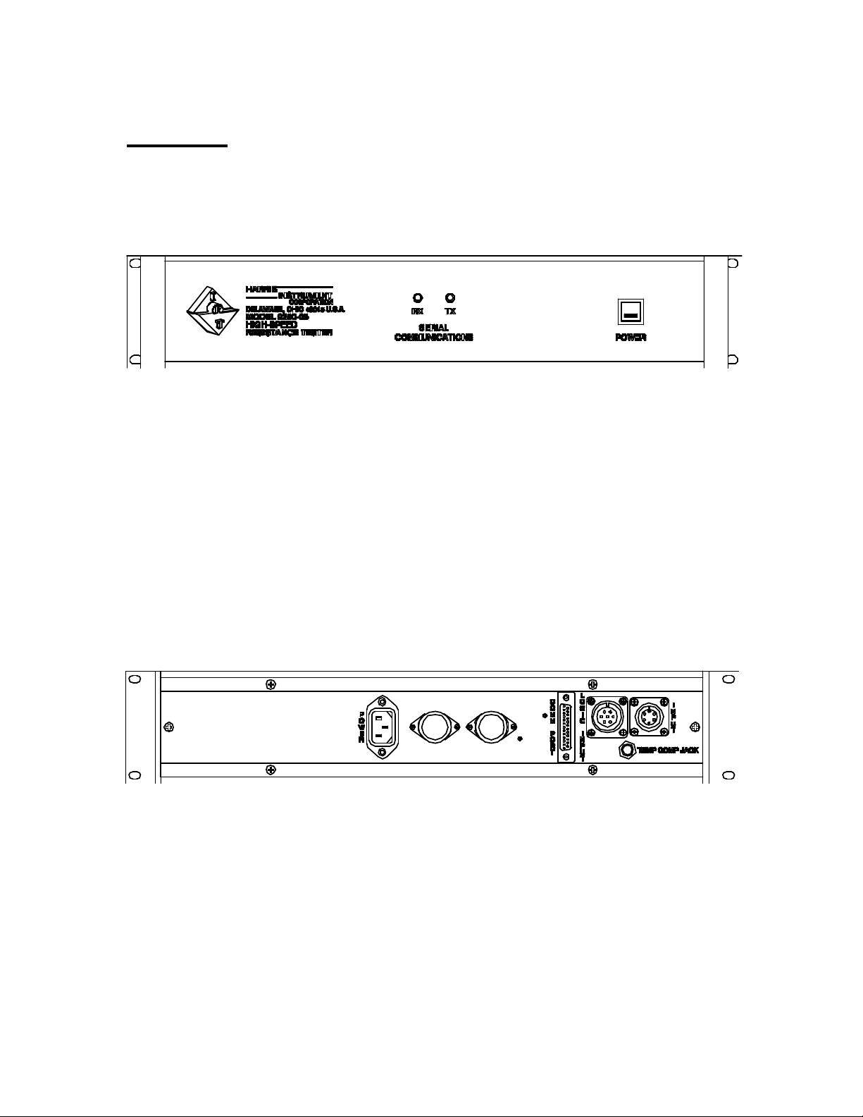
current range and automatically switches to the lower range. A lighted ON/OFF push-button
switch is mounted on the front panel of the unit, along with two red LED lamps that indicate when
the serial communications link is functioning.
Figure 1: Typical Model 9250-05 Front Panel
Figure 2: Typical Model 9250-05 Back Panel

9250-05-Manual.DOC
07/19/00
High-Speed Resistance Tester – Model 9250-05
Operators Manual
3
The Model 9250-05 also includes a relay output which may be triggered via high/low limits (set via
the computer interface) permitting the automated rejection (GO/NO-GO) of unacceptable
components. To protect the instrument from high voltage damage, there is a safety relay that locks
out the resistance tester during high-pot or surge tests.
A Temperature Compensation probe input is available for measuring the ambient temperature. An
infrared Temperature Compensation Probe is available for measuring the temperature of the part
under test by the Model 9250-05. The temperature range is 0 - 120ºC with an accuracy of ±2ºC.
The temperature is available over the serial communications link.
Computer Interface
The resistance ranges are selected and data returned by ASCII commands via the serial
communications link to either a host computer or the LED Option Customer Interface. The unit
requires a RS-232 command to begin sending, and to stop, resistance readings. The Model 9250-
05 returns the measured data within 10msec over the RS-232 communications link (format
X.XXXX followed by a carriage return/line feed) with a floating decimal point matching the
selected range. Resistance range changes and temperature readings may be polled from the link.
Calibration is performed by placing a calibration standard for each range across the resistance
tester inputs and transmitting a calibration command for each range.

9250-05-Manual.DOC
07/19/00
High-Speed Resistance Tester – Model 9250-05
Operators Manual
4
Operational Considerations
The Model 9250-05 is highly resistant to most of the industrial environments that can cause
problems with resistance test equipment. The operating temperature of the Model 9250-05 is 32ºF
to 122ºF [0ºC to 50ºC]. Operations outside this range should be avoided. Temperature
compensation for resistance readings is detailed in the TC Option section (if applicable).
NOTE:
If any welding is to be performed near the Model 9250-05, or
anywhere on the process line where the Model 9250-05 is installed,
disconnect ALL cables from the Model 9250-05. This prevents system
overload by the current generated from welding.
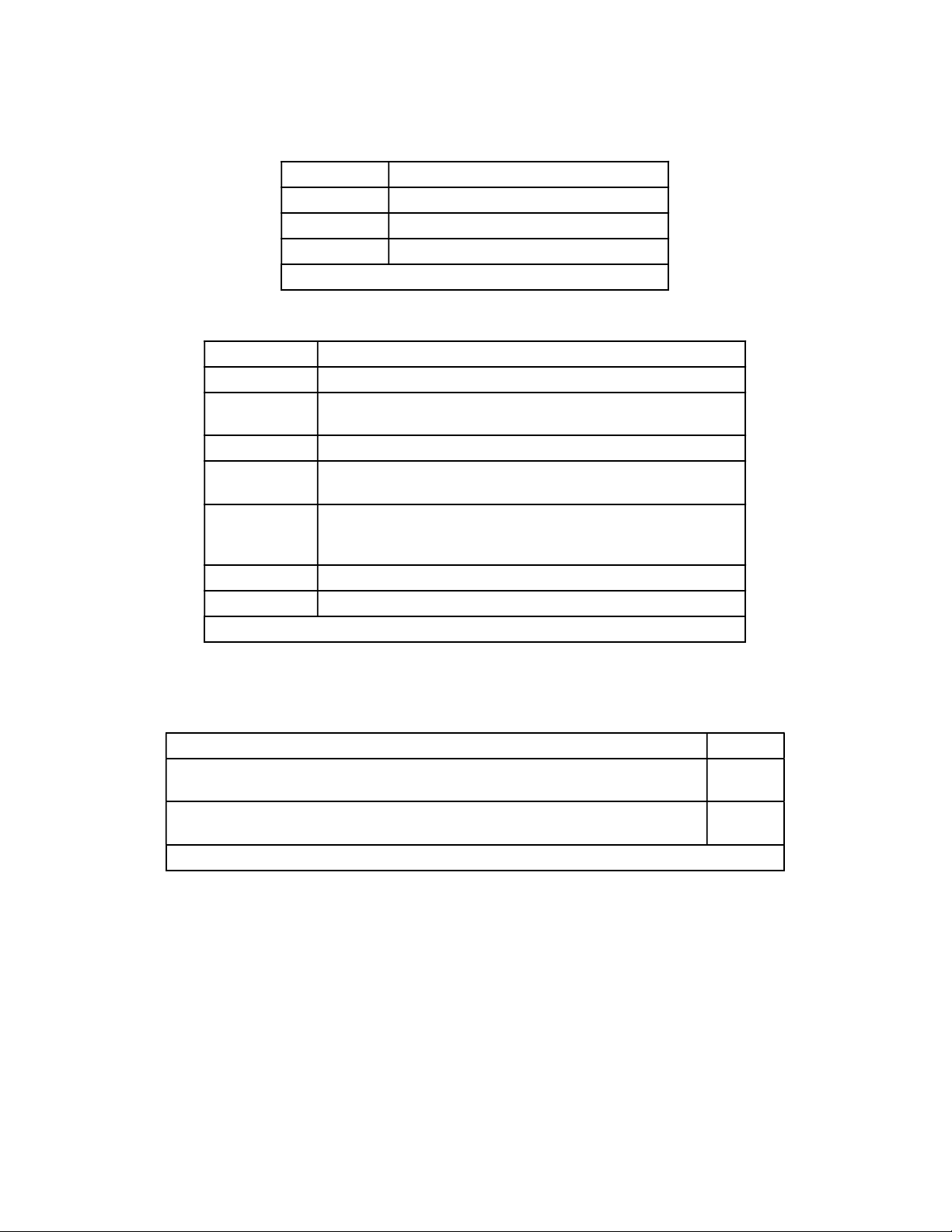
Manual Conventions
Throughout this manual section, there are many keyboard commands that will be used to signify
command sequences. Different fonts will be used for the keyboard commands. The following
table describes these commands and keystrokes.
Key Description
Space Bar
Enter Key
Command Sequence Start
Backspace
Caps Lock
Keystroke
*S Communications Software Response
Mouse Action on Host Computer
Table 1: Manual Conventions
Power Switch
A lighted push-button power switch is located on the front panel of the Model 9250-05. This
switch is the master power switch for the unit. If this switch is pushed in, the green LED lamp
should light. If the lamp does not illuminate, check the power line cord connections to ensure that
the unit has power. If the unit does have power and the lamp will still not illuminate, contact Harris
Instrument Corporation IRT Service for more information.
9250-05-Manual.DOC
07/19/00
High-Speed Resistance Tester – Model 9250-05
Operators Manual
5
Product Specifications
The Model 9250-05 is available with a variety of standard and optional features which allow the
unit to meet a wide range of industrial resistance testing requirements.
Power
Power Supply (rated at 122ºF [50ºC]):
105VAC - 125VAC @ 50Hz - 60Hz, 2.0Amp Maximum, 250Watts Maximum;
208VAC - 248VAC @ 50Hz - 60Hz, 1.0Amp Maximum, 250Watts Maximum.
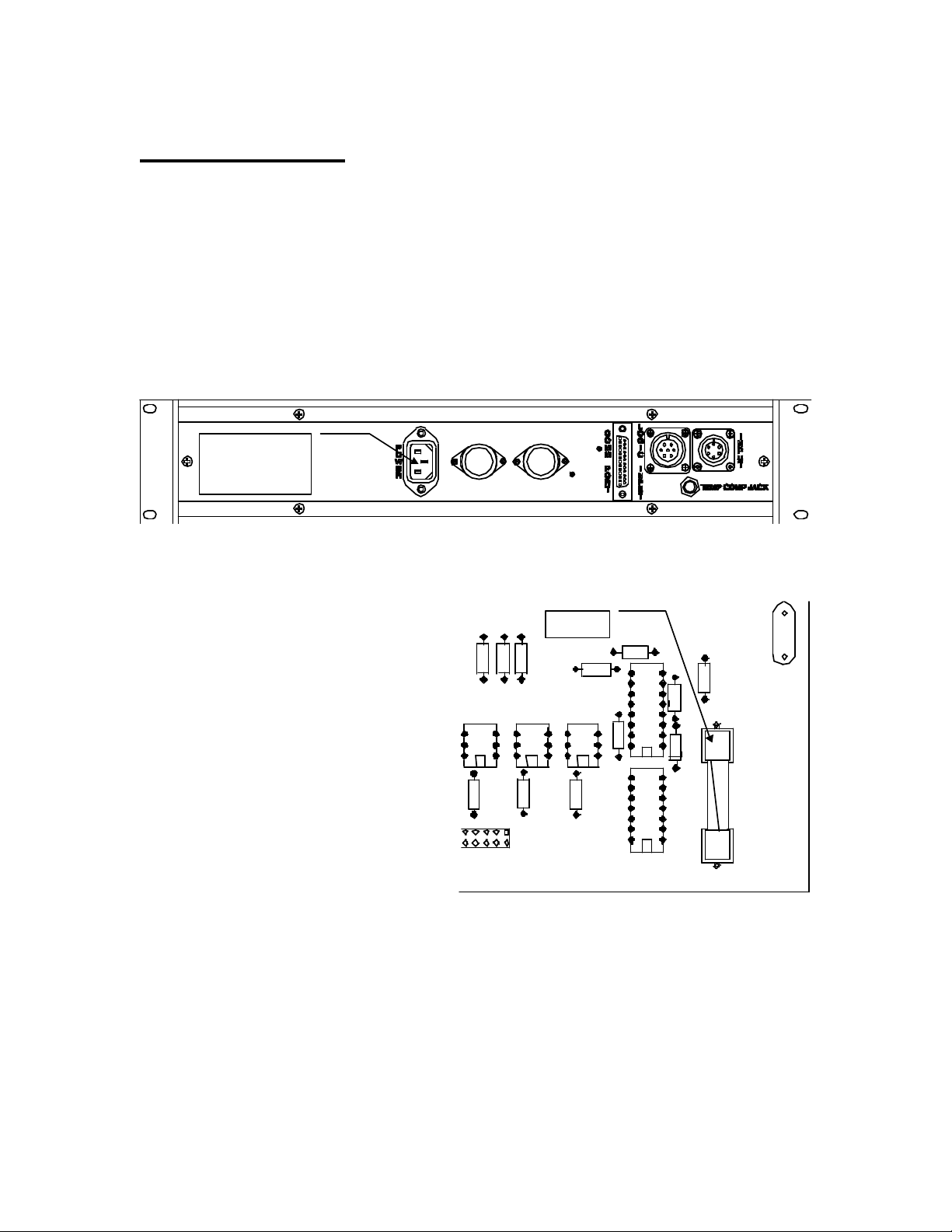
Power connection is via a three-prong HP-
style enclosed connector on the back panel
of the unit.
The power line is filtered to suppress power
line transient noise and power line induced
RF interference. Quick disconnect power
line connections are made directly to the
internal power line filter inside the enclosure.
The input power is fused with a 2Amp Slo-
Blo type 3AG fuse. See Figure 4 for fuse
location.
Accuracy
±0.02% of Full Scale
±1 digit at 25ºC
±0.02% per ºC for 0ºC - 50ºC.
Figure 3: Power Connection for Model 9250-05
Figure 4: Fuse Location on 3696032 Board
Fuse
HP-Style
Power Cord
Connector
9250-05-Manual.DOC
07/19/00
High-Speed Resistance Tester – Model 9250-05
Operators Manual
6
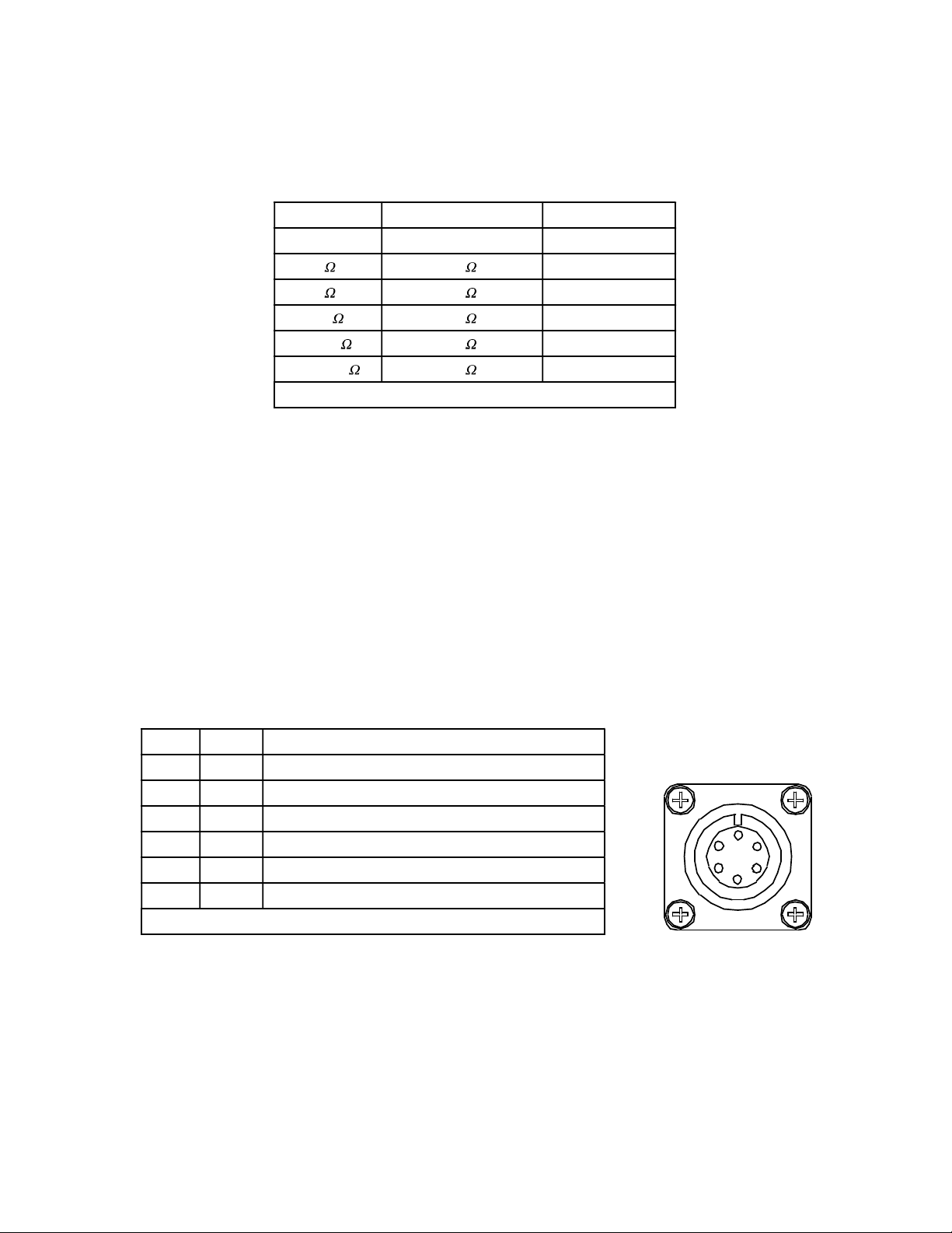
Resolution
The resolution of the Model 9250-05 is based upon the range of resistance tests being performed.
Range Resolution (4½-digit) Range Number
0 None 0
0 - 0.2 0.00001 1
0 - 2.0 0.00010 2
0 - 20.0 0.00100 3
0 - 200.0 0.01000 4
0 - 2000.0 0.10000 5
Table 2: Resolution Specifications and Range Numbers
The Range Number in Table 2 is the value (X) entered with the Set Range command.
Connections
There are several connectors on the back panel of the Model 9250-05 for attachment of terminals,
RS-232, resistance inputs, and logic inputs.
Terminal INPUT Connector
The six-pin MS-Style female circular connector on the back panel of the unit is for the current and
voltage terminals, and the GO/NO-GO relay (dry contact closure) output. A 4-wire Kelvin
connection is required. No internal snubbing is provided for the relays. All voltages are compliance
voltages.
Pin # Term Function
AI - Current Minus – 5VDC @ 1Amp Full Scale
BI + Current Plus – 5VDC @ 1Amp Full Scale
C - - - GO/NO-GO Relay – 2A @ 30VDC, 1/2A @ 120VAC
D - - - GO/NO-GO Relay – 2A @ 30VDC, 1/2A @ 120VAC
EV - Voltage Minus – 5VDC @ 1Amp Full Scale
FV + Voltage Plus – 5VDC @ 1Amp Full Scale
Table 3: 6-pin Terminal INPUT Circular Connector Pinouts
Figure 5: INPUT
Connector
A
B
C
DE
F
9250-05-Manual.DOC
07/19/00
High-Speed Resistance Tester – Model 9250-05
Operators Manual
7
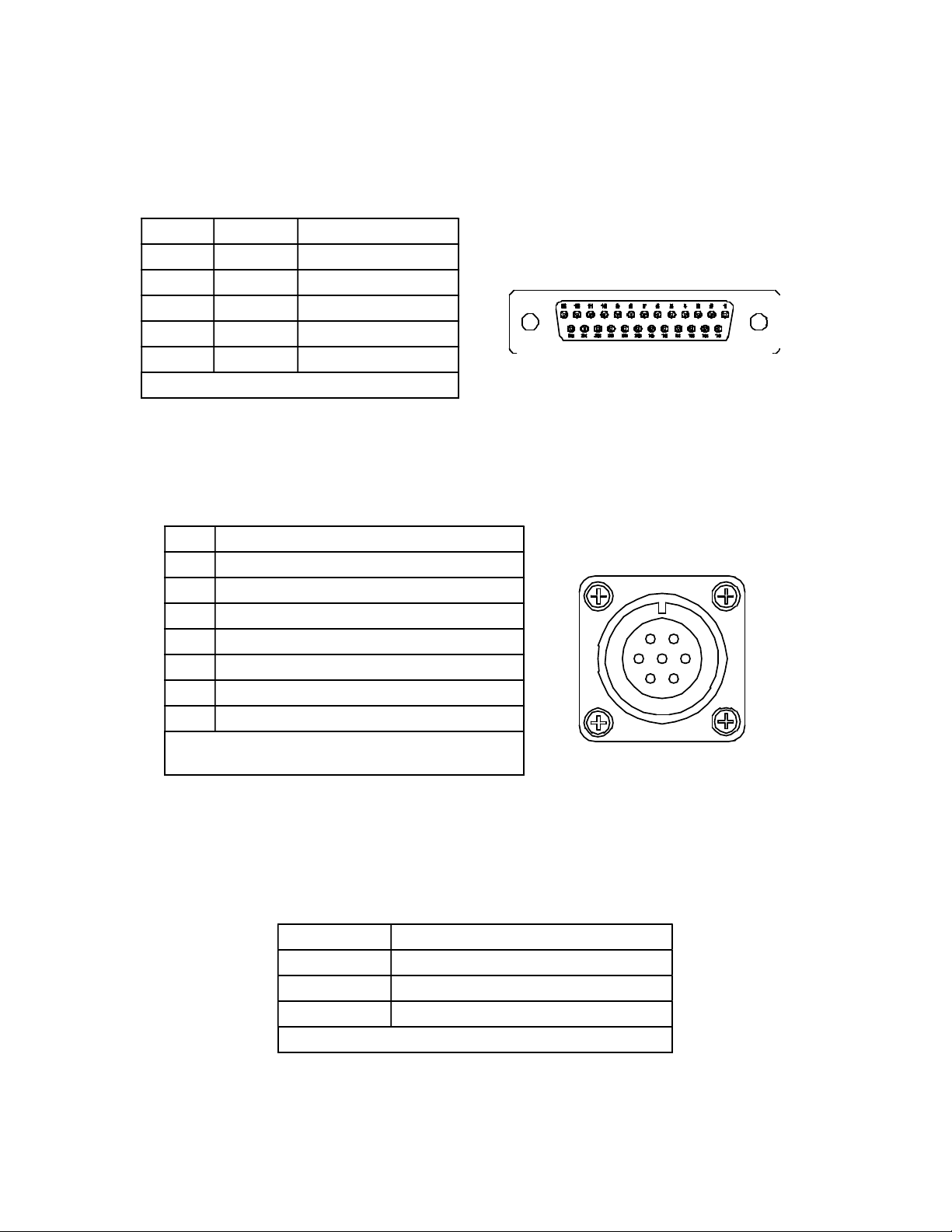
Serial Communications Connector
The Serial Communications Connector is a female D-Shell Sub-Miniature 25-pin connector (DB-
25) for the Serial Communication Link. This connector uses the RS-232C protocol.
Pin # Term Function
2 TX Transmit Data
3 RX Receiver Data
5 CTS Clear-to-Send
7 GND Signal Ground
20 DTR Data-Terminal Ready
Table 4: DB-25 Connector Pinouts
LOGIC INPUT Connector
Several logic inputs to the Model 9250-05 are available via the 7-pin MS-style female circular
connector on the back panel {Figure 7}.These inputs are not currently defined and will be
available by custom order in the first quarter of 1998.
Pin # Function
A Input 1
B +5VDC
C Input 4
D Input 3
E Input 2
F LOGIC COMMON
G GROUND
Table 5: 7-pin Logic INPUT Circular Connector
Pinouts
Physical Dimensions
The standard Model 9250-05 is provided in a 19 inch [483mm] rack mount case.
View Dimension
Front Panel 19.00" [483mm] wide x 3.50" [89mm] tall
Side Panel 14.00" [356 mm]
Back Panel 17.00" [432mm]
Table 6: Rack Mount Case Dimensions
Figure 6: DB-25 Connector Pinouts
Figure 7: Logic Input
Circular Connector
2
3
5
7
20
A
B
CD
E
F
G
9250-05-Manual.DOC
07/19/00
High-Speed Resistance Tester – Model 9250-05
Operators Manual
8
A bench top model is also available (optional).
View Dimension
Front Panel 11.25" [286mm] wide x 3.75" [95mm] tall
Side Panel 14.00" [356mm]
Back Panel 11.00" [279mm]
Table 7: Bench-top Case Dimensions
Optional Configurations
Option Description
TC Option Temperature Compensation – Measures ambient temperature.
IRTC Option Infrared Temperature Compensation – Measures temperature of
part under testing by Model 9250-05.
MPI Option Multiplexing Input – Multiple test input.
LED Option LED Display/Keypad Customer Interface – Remote display and
keypad for entry of commands and control of the Model 9250-05.
LCD Option
LCD Touchscreen Customer Interface – Remote touch screen
for entry of commands and control of the Model 9250-05
(availab le first quarter 1998).
HR Option High Resistance Testing (available first quarter 1998).
LR Option Low Resistance Testing (availab le first quarter 1998).
Table 8: Options for Model 9250-05
Accessories
Several accessories for the Model 9250-05 are available from Harris Instrument Corporation.
Accessory Nam e
Circular Mating Connector for INPUT 6-pin MS-Style circular connector (supplied
with every Model 9250-05). -97
Circular Mating Connector for LOGIC INPUT 7-pin MS-Style circular connector
(supplied with every Model 9250-05 in first quarter 1998). -97/7
Table 9: Accessories for Model 9250-05

9250-05-Manual.DOC
07/19/00
High-Speed Resistance Tester – Model 9250-05
Operators Manual
9
Model 9250-05 Commands
The Model 9250-05 is controlled by a host computer. A remote LED Display/Keypad is also
available and is detailed in the DK Option section of this manual (if applicable).
The following commands must be entered in FULL CAPITAL LETTERS, proceeded by an
asterisk symbol (*). The command sequencer is case sensitive, so setting the CAPS LOCK key to
ON with the host computer is recommended.
Comm and Sequence Description
Set Averaging: Numb er of averages (1 - 10000, 60).
Set Baud Rate: 9600, 19200, 38400, 57600.
Calibrate: Calibrate current range at XXXXXX .
Set Line SYNC: Power line SYNC set OFF.
Set UPPER Limit: Set high limit at XXXXXX .
Start Readings: Begin sending resistance readings.
or Display Help Screen.
Set Line SYNC: Power line SYNC set ON.
Set LOWER Limit: Set the low limit at XXXXXX .
Set Range: Change to x resistance range (0, 1, 2, 3, 4, 5).
Stop Readings: Stop sending resistance readings.
Set Auto-Range: Auto-range mode set ON.
Set Auto-Range: Auto-range mode set OFF.
Diagnostics – Displays the raw counts from the analog-to-digital
converter for calib ration and troubleshooting.
Reset: Sets all user selected variab les to factory default.
Table 10: Command Sequence Listing
Commands for Temperature Compensation – TC & IRTC Options, can be found in the TC
Option section. Commands for the Multiplex Input Option – MPI Option, can be found in the MP
Option section. Operation with the LED Display/Keypad – LED Option, is documented in the DK
Interface section, while operation with the LCD Touchscreen Display – LCD Option, is covered
in the LCD Section.
Data Entry Conventions
All data entered in XXXXXX entries (LOW Limit, HIGH Limit, etc.) may be entered as 1 to 10
digits with a decimal point if necessary. The decimal point position on all displayed variables
matches current customer selected decimal point position. Up to ten command sequences may be
sent in rapid succession by the terminal device EXCEPT the calibration command and the factory
default command.
9250-05-Manual.DOC
07/19/00
High-Speed Resistance Tester – Model 9250-05
Operators Manual
10
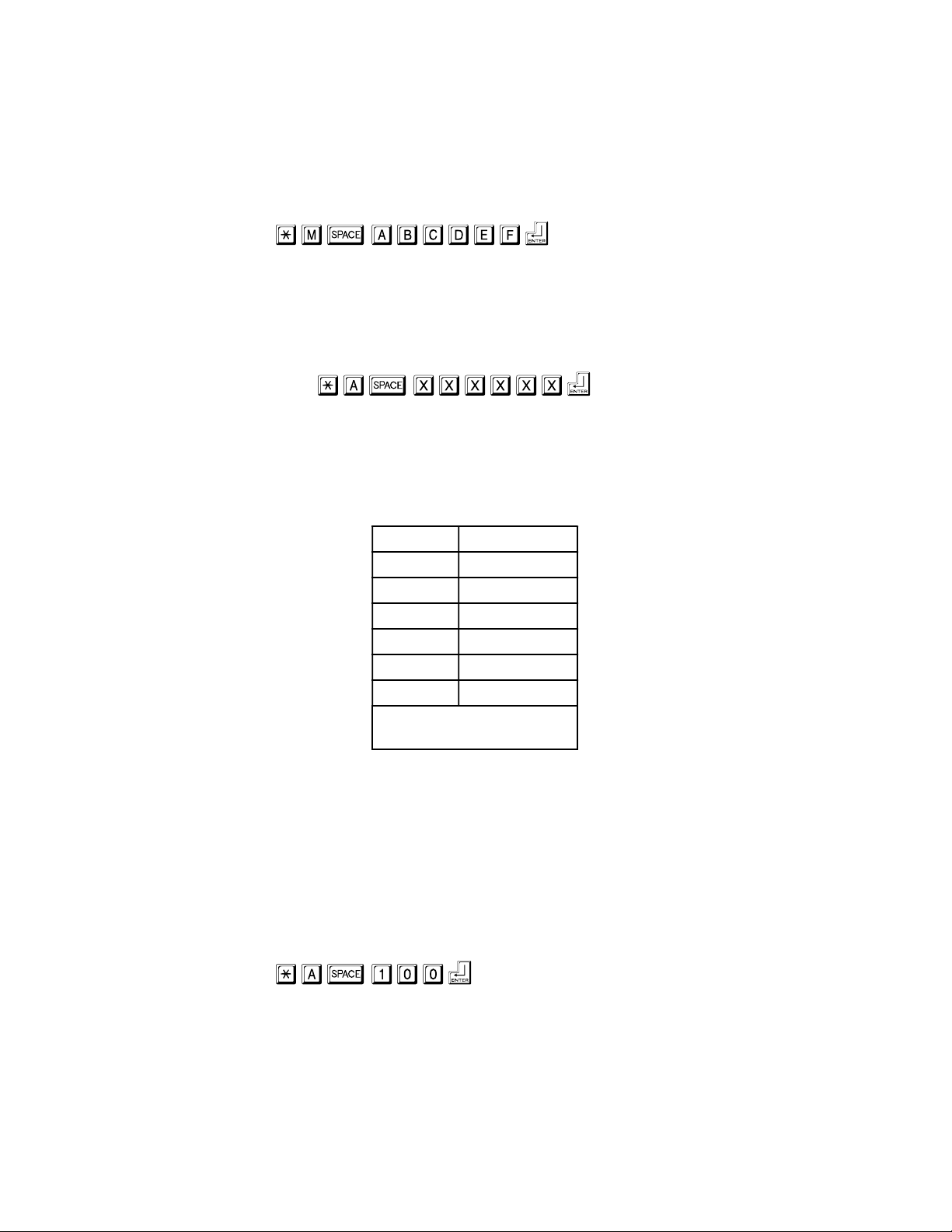
Invalid Command Response
Any time an invalid command is sent via the serial communications link to the Model 9250-05, the
system will respond with a “What?” statement. The following example shows the Set LOW Limit
command being used with an improper sequence.
Command> *M ABCDEF
What?
Any time a “What?” response is received in the communications terminal software, check the
command sequence that was previously entered and re-enter the command sequence properly.
Averaging Setting:
The Set Average command will change the number of averages that will be used to calculate the
resistance reading using the example formula (XXXXXX = number of readings, factory default
value is 60 readings) on the next page.
The averaging value will affect the update rate as shown in Table 11 (9600 baud):
Setting Update Rate
1 110Hz
100 83Hz
200 33Hz
500 15Hz
1000 8Hz
10000 0.8Hz
Table 11: Update Rates with
Averaging Settings
Higher baud rate settings will increase the update rate.
Example: 57600 baud with averages @ 1 = 250Hz update rate.
Averaging Formula:
Output reading = (SUM of readings) divided by setting value.
Example: A total of 100 readings is required for averaging. Enter the following command
sequence for setting the averaging:
Command> *A 100
The 100 readings are totaled and divided by 100 to give the average readings. With no averaging,
the actual readings will be displayed.
Typically, the averaging setting is 60 with Line SYNC set on. This gives the best overall output for
the system.

9250-05-Manual.DOC
07/19/00
High-Speed Resistance Tester – Model 9250-05
Operators Manual
11
Baud Rate Setting:
The Set Baud Rate command will change the serial communications baud rate (bps). The valid
baud rates are (underlined rate is the factory default):
9600, 19200, 38400, 57600.
Example: Setting the baud rate to 19200
Command> *B 19200
See System Operation – Serial Communications for more information on the serial
communications link.
Resistance Calibration:
NOTE:
Any units delivered from the factory with certified calibration
SHOULD NOT BE RE-CALIBRATED by the operator.
This WILL void the certified calibration.
Calibration of the Model 9250-05 is performed by placing a calibration standard, near the full scale
resistance for each range, across the meter inputs and transmitting a calibration command for the
current selected range over the serial communications link.
Command>*C XXXXXX
When the full scale reading is complete, the unit will prompt the operator to insert a lower (10% of
first standard) resistance standard across the meter inputs. This will assures an accurate zero
reference point for each range.
Example: Calibrating to a 1.9 resistance standard.
Command>*C 1.9000
Command> Please insert a low resistance
standard
Line SYNC Commands
There are two commands for setting line SYNC, ON or OFF.
Line SYNC ON:
This command turns the power line synchronization ON (maximum update rate is now 60Hz).
This allows the Model 9250-05 to give steady readings output.

9250-05-Manual.DOC
07/19/00
High-Speed Resistance Tester – Model 9250-05
Operators Manual
12
All Set Averaging values from 1 to 60 will output at 60Hz with Line SYNC set ON. Averaging
values higher than 60 will result in update rates lower than 60 Hz with Line SYNC set ON.
Line SYNC OFF:
This command will turn the power line synchronization off. Line SYNC ON is the factory default
for the Model 9250-05.
Limit Settings
High and low limit settings are available with the Model 9250-05. The Set UPPER Limit command
sets the high limit and the Set LOWER Limit command sets the low limit.
Set UPPER Limit:
Enter the UPPER Limit in OHMS, with the appropriate decimal point. When resistance =
1.5000 and the high limit = 1.4900 the “GO” relay will be open.
Example: Set UPPER Limit to 20.500.
Command> *E 20.500
Set LOWER Limit:
Enter the LOWER Limit in OHMS, with the appropriate decimal point. When resistance =
1.0999 and the low limit = 1.1000 the “GO” relay will be open.
Example: Set LOWER Limit to 10.500.
Command> *M 10.500
Start Readings:
The Start Readings command will initiate the sending of resistance readings for the current range.
The measured data will be in the following format (this reading is for Range One):
.XXXXX
Note that the decimal point will move, depending upon which range is being tested (i.e. Range
Two = X.XXXX, for Range Three = XX.XXX, etc.).
HELP Screen: or
This displays a screen with all of the command sequences listed with short descriptions and value
ranges. Also displayed is a short summary of many of the settings for the system under Current
Settings.
9250-05-Manual.DOC
07/19/00
High-Speed Resistance Tester – Model 9250-05
Operators Manual
13
Sample HELP Screen output:
Command> *H
*A_XXXXX - Number of averages (1-10000).
*B_XXXXX - Set baud rate (9600, 19200, 38400, 57600).
*C_XXXXXX - Calibrate current range at XXXXXXohms.
*E_XXXXXX - Set the UPPER Limit at XXXXXXohms.
*G - Output resistance readings, *S - Stop sending readings.
*H - (Help) Sends this output.
*K_XXXXXX - Set temperature coefficient.
*I - Temperature Compensation ON, *J - Temperature Compensation OFF.
*L - Line SYNC ON, *D - Line SYNC OFF.
*M_XXXXXX - Set the LOWER Limit at XXXXXXohms.
*Q_XX.X - Set reference temperature for compensation.
*RX - Change to X resistance range (0, 1, 2, 3, 4, 5).
*T - Output the current temperature.
*U - Auto-range mode ON, *V - Auto-range mode OFF.
*X - Multiplexer command string, *X 1-2R4,4-9R1,3-7R2.
*Y_XX.X - Temperature calibration point.
Current Settings - Range: 2 ohm
Averages: 00060 Baud rate is now: 9600
High Limit: 1999.99 Low Limit: .000
The line synchronization is: ON
Temp. Compensation: OFF
Temperature Coefficient: .00393
Reference Temperature: 25.0
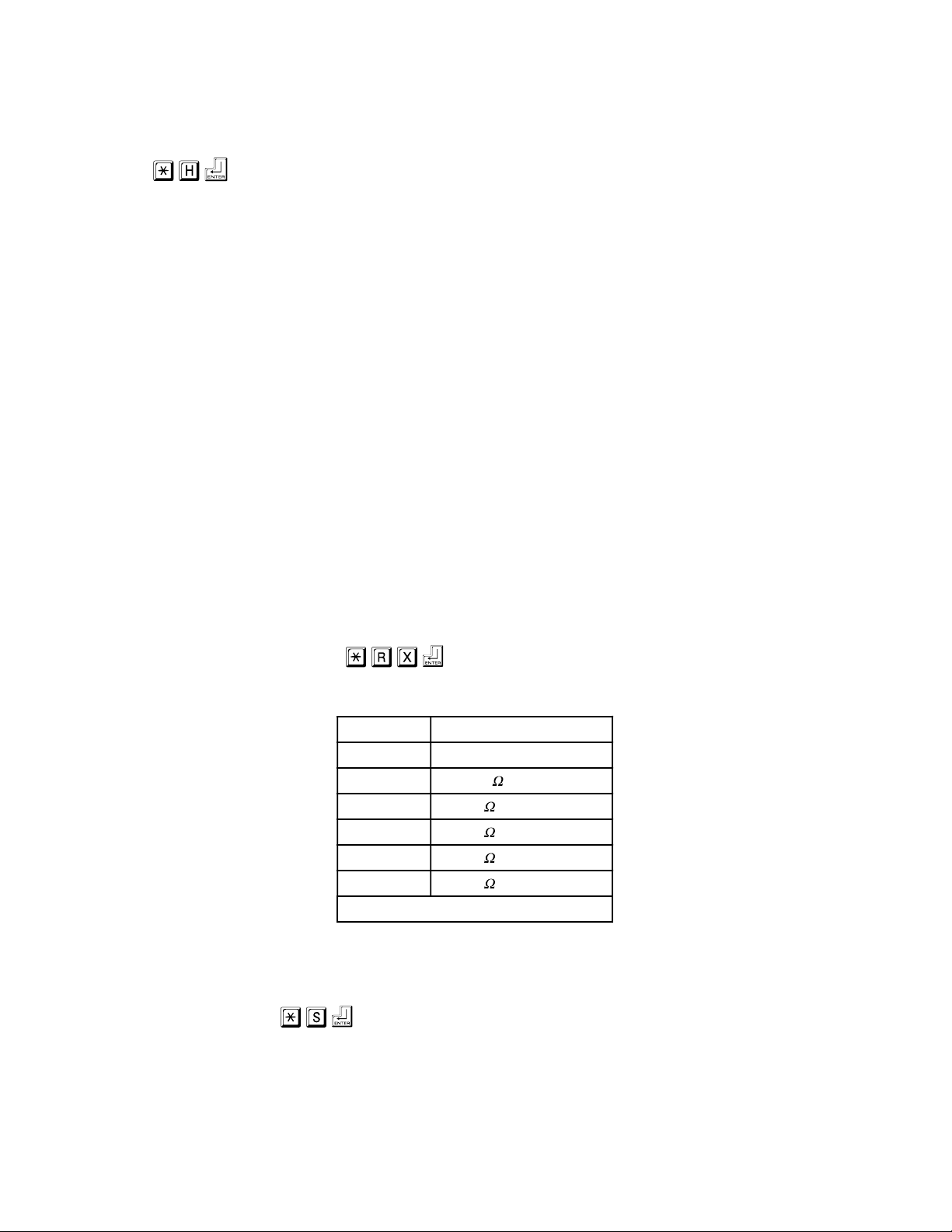
Set Resistance Range:
The resistance range may be changed by the Set Resistance Range command. Valid settings are:
Setting Range
0 Turns off Safety Relay
1 0.20000
2 2.0000
3 20.000
4 200.00
5 2000.0
Table 12: Resistance Range Settings
If an invalid range for the test is selected, the unit will default to Range 2 (2). The unit will
default to no relays on (Range 0) at power up.
Stop Readings:
When the Model 9250-05 is powered on, the unit is in IDLE Mode. It is taking no readings in this
mode. After the Start Readings command or the Send Temperature command are given, the unit

9250-05-Manual.DOC
07/19/00
High-Speed Resistance Tester – Model 9250-05
Operators Manual
14
can be returned to IDLE Mode with the Stop Readings command. Also, any command entered
(except Start Readings or Send Temperature) will return the unit to the IDLE Mode.
Auto-Range Selection
One of the premiere features of the Model 9250-05 is the Auto-Range Selection. The Auto-Range
command begins the automatic selection of the resistance range. When the measured resistance
falls below 10% of the current range, the meter will automatically switch to the next lower range.
Set Auto-Range ON:
Turn on the automatic ranging feature.
Set Auto-Range OFF:
Disables the automatic range selection. The meter will remain on the last selected range until a
new range command is issued. Auto-Range OFF is the factory default.
Diagnostic Output:
Displays the raw counts from the analog-to-digital converter. Used in calibrating the system.
Restore Factory Defaults:
This command will reset the stored system settings to the factory defaults. Calibration values are
not affected by this command.
Factory Default System Settings are:
Serial Communications: 9600 Baud Rate
Resistance Range: Range 0
Auto-Range: OFF
Averages: 60
Power Line SYNC: ON
Temperature Compensation: OFF

9250-05-Manual.DOC
07/19/00
High-Speed Resistance Tester – Model 9250-05
Operators Manual
15
System Operation
Before applying power to the Model 9250-05, set up the communications software that will be
used to interface with the Model 9250-05. Also be sure that the communications lines are installed
and attached to the Model 9250-05 and the host computer.
Serial Communications
The host computer serial communications interface for the Model 9250-05 is based upon the DEC
VT-100 (ANSI) terminal emulation for the IBM PC®for RS-232 communications. The RS-232
output communications port operates as the DCE, with the host computer as the DTE. Any ANSI
terminal emulator will probably function with the Model 9250-05 as a terminal emulator, as well as
many commercial communications software packages (such as PROCOMM®).
Communications protocol for the serial output are RS-232C ASCII, six-characters with a decimal
point, space padded with a carriage-return and line feed in a 10-bit frame running:
No Parity, Eight Data Bits and One Stop Bit (N,8,1)
with One Start Bit.
The communications can be set for a baud rates of (underlined is factory default):
9600bps, 19200bps, 38400bps, 57600bps.
When setting up for operation with a personal computer (PC), be sure that no other serial devices
are sharing the communications port on the PC. The Model 9250-05 requires a standard
communications port for operation.
For this manual, the Windows® TERMINAL program will be used as an example communications
program for interfacing with the Model 9250-05. The Windows® TERMINAL communications
program must be configured to operate with the Model 9250-05.
RX/TX Lamps
In the middle of the front panel of the Model 9250-05 are two red lamps labeled RX and TX.
These lamps will illuminate when RS-232 communications are in operation. Whenever commands
are being received by the Model 9250-05, the RX lamp will illuminate and whenever the unit is
transmitting data to the host computer (or LED Display/Keypad Customer Interface – DK Option
section), the TX lamp will illuminate.
If these lamps do not light when power is on to the unit AND the host computer is sending
commands to the Model 9250-05, verify that the serial communications cable is properly attached
at both ends. If the lamps still will not illuminate, contact Harris Instrument Corporation IRT
Service for more information.

9250-05-Manual.DOC
07/19/00
High-Speed Resistance Tester – Model 9250-05
Operators Manual
16
Configuring Windows® TERMINAL
The following example on the next page is based upon the Microsoft® Windows® for Workgroups
TERMINAL software program. This program is used because of the commonplace occurrence
of it on most DOS-based computer systems today. Any DEC VT-100 (ANSI) compatible terminal
emulation program can be used to communicate with the Model 9250-05 RS-232 customer
interface.
Terminal Start TERMINAL.EXE (located in the Accessories or Main
Program Group).
Settings Open the Settings Menu and select Terminal Emulation...
Terminal Emulation...
Verify that the DEC VT-100 (ANSI) Terminal Emulation is
selected. If it is not selected, click on the DEC VT-100
(ANSI) choice.
OK
Click on OK to close the Terminal Emulation dialog box.
Open the Settings menu again and select
Communications...
Settings
Communications
Select under the CONNECTOR Scroll Box the proper
communications port on the host computer that is connected
to the Model 9250-05. Typically, this w ill be COM2 as the
mouse for Window s®is typically on COM1 .
COM2 Select the 9600 Radio Button in the BAUD RATE area.
9600 Select the 8 Radio Button in the DATA BITS area.
8Select the 1 Radio Button in the STOP BITS area.
1Select the None Radio Button in the PARITY area.
None Select the None radio button in the FLOW CONTROL area.
None Click on OK to Close the COMMUNICATIONS Dialog Box.
SETTINGS Open the Settings menu.
Modem Commands Select Modem Commands...
None Select the None radio button in the Modem Defaults area.
OK Close the Modem Commands dialog box.
File Save the settings for operating the Model 9250-05 by
choosing the Save As function under the File menu.
Save As... Save file as 9250.TRM
OK Click on OK to close the File dialog box.
Now, whenever starting Terminal to operate the Model 9250-05, load the file 9250.TRM and the
settings for the Model 9250 factory defaults will be available.

9250-05-Manual.DOC
07/19/00
High-Speed Resistance Tester – Model 9250-05
Operators Manual
17
Verify Communications
If the Model 9250-05 is connected correctly to the host computer and the TERMINAL or other
communications software is configured properly, when power is applied to the Model 9250-05 the
communications software should respond within ten seconds with:
Warm up!
After approximately four to five seconds, the output will read:
Power up!
Once the power up message is displayed, the unit is in IDLE Mode. It is not taking readings from
the terminal probes. To start taking readings, issue the Start Readings command; or configure the
unit with one of the other commands.
NOTE:
The Model 9250-05 is a precision resistance measurement instrument
and requires a warm-up period of approximately five minutes
BEFORE readings should be taken.
Also, verify that the RX and TX lamps on the front of the Model 9250-05 are illuminating when
the unit is receiving commands (RX) or transmitting data (TX).
If the unit will not issue the power up messages within ten to twenty seconds, check the serial
communications cable to ensure that it is connected properly. Also check that power is applied to
the unit (green LED indicator on ON/OFF push-button switch is illuminated). If both of these
checks are valid, contact Harris Instrument Corporation IRT Service for more information.

9250-05-Manual.DOC
07/19/00
High-Speed Resistance Tester – Model 9250-05
Operators Manual
18
Model 9250-05 Calibration
Calibration of the Model 9250-05 is relatively simple as the adjustments to the system are all
software-controlled. The following example details the calibration of the unit.
NOTE:
Any units delivered from the factory with certified calibration
SHOULD NOT BE RE-CALIBRATED by the operator.
This WILL void the certified calibration.
To perform the following Calibration Procedure later in this manual, it is suggested that you obtain
six resistors or resistance standards. The values of these standards for this example are:
1.9K ±10%, 190 ±10%, 19 ±10%, 1.9 ±10%, 0.19 ±10%, and 0.019 ±10%.
Almost any standard or resistor can be used for the Calibration Procedure, as long as they match
the ranges of the meter and are 10% of the higher standard.
Calibration Example
1) Apply power to the Model 9250-05.
WARM UP!
POWER UP!
The unit will respond with “WARM UP!” within ten seconds and “POWER UP!” in another four
to five seconds.
2) Perform the Set Averaging command and set the number of readings to average to 60.
Command> *A 60
The Averaging value is now set to 60.
3) Set Line SYNC ON.
Command> *L
The Line Sync is now enabled.
4) Disable the Auto-Range function.
Command> *V
The Auto-Range command has been disabled.

9250-05-Manual.DOC
07/19/00
High-Speed Resistance Tester – Model 9250-05
Operators Manual
19
5) Disable Temperature Compensation, if applicable.
Command> *J
Temperature Compensation is now disabled.
6) Place a 1.9K ±10% resistance standard on the resistance test inputs to the Model 9250-05.
7) Perform the Set Resistance Range command for the 2K range – Range 5.
Command> *R5
The unit is now set for testing in the 2K range.
8) Display the Diagnostic Output for verification of resistance reading.
Command> *Z 61,234
Verify that the reading output is 60,000 ± 3,000. If out of range, then verify connections to the
resistance tester and that the range is set correctly.
9) Stop diagnostic readings.
Command> *S
10) Begin the Resistance Calibration command.
Command> *C 1900.0
The unit will now prompt you to connect a lower resistance standard (199 ±10%) to the unit and
then enter the value of the low resistance standard.
Command> Please insert a low resistance
standard
11) Enter the value of the 1.9 standard.
Command> 1.9
The 2K range is now calibrated.
12) Repeat steps 6 through 11 to calibrate the remaining ranges substituting the following values
for step 6 and step 7.
Step 6 Step 7 Step 11
199 ±10% *R4 199.00
19 ±10% *R3 19.000
1.9 ±10% *R2 1.9000
0.19 ±10% *R1 0.1900
Re-enable any applicable functions and options.
Table of contents
Other Harris Test Equipment manuals


Popular Test Equipment manuals by other brands


iqualitrol
iqualitrol iRock-439T instruction manual

Dräger
Dräger 8103530 Instructions for use

Keysight Technologies
Keysight Technologies InfiniiVision M9241A SCPI Programmer's Guide

The Diagnostic Box
The Diagnostic Box TDB760 operating manual

TESTO
TESTO 175-H2 manual

Dräger
Dräger Alcotest 7410 GLC Operator's manual


