Harris 156593 Guide

5718 52nd Street Kenosha WI 53144|Orders and Customer Care: 1-866-616-1270|Fax: 1-866-616-1271|HarrisPoolProducts.com
Sand Filter
Systems
Item #s 156593, 156594 & 156595
▲WARNING
This equipment must be installed and serviced by a qualied technician in accordance with all applicable codes
and ordinances. Improper installation can create hazards which could result in property damage, serious injury
or death. Improper installation will void the warranty. The NOTICE label indicates special instructions that are
important but not related to hazards.
Notice to Installer
This manual contains important information about the installation, operation and safe use of this product. Once
installation is complete, this manual must be given to the owner / operator of this equipment.
INSTALLATION, OPERATION & PARTS

5718 52nd Street Kenosha WI 53144|Orders and Customer Care: 1-866-616-1270|Fax: 1-866-616-1271|HarrisPoolProducts.com
CHAPTER 1:
IMPORTANT SAFETY INSTRUCTIONS
READ AND FOLLOW ALL INSTRUCTIONS
1. The Sand Filters are designed to work with water
at a temperature from 32ºF and 113ºF. The
lter should never be operated outside of these
temperatures or damage may occur.
2. The installation should be carried out in accordance
to the safety instructions of swimming pools and
the specic instructions for each facility.
3. The user should make sure that the installation is
carried out by qualied authorized persons and that
these persons have rst carefully read the following
instructions. Incorrectly installed equipment may
fail, causing severe injury or property damage.
4. The operating safety of the lter is only guaranteed if
the installation and operation instructions are
correctly followed.
5. To reduce the risk of injury, do not permit children
to use this product.
6. Incorrectly installed equipment may fail, causing
severe injury or property damage.
7. Chemical spills and fumes can weaken Swimming
Pool or Spa. Corrosion can cause lters and other
equipment to fail, resulting in severe injury or
property damage. Do not store pool chemicals near
your equipment.
8. Any modication of the lter requires the prior
consent from the supplier’s original replacement
parts and accessories authorized by the
manufacturer ensure a high level of safety. The
supplier assumes no liability for the damage and
injuries caused by unauthorized replacement parts
and accessories.
Sand Filtration System Working Principle
Incoming water from the piping system is automatically
directed by the Multi-Port Valve to the top of the lter
bed. As the water is pumped through the lter sand,
dirt and debris are trapped by the lter bed, and ltered
out. The ltered water is returned from the bottom of
the lter tank, through the Multi-Port Valve and back
through the piping system.
CHAPTER 2: PREPARATION BEFORE INSTALL
▲WARNING This product should be installed and
servicedonlybyaqualiedprofessional.
1.
Position the lter next to the Swimming Pool or Spa.
2. The lter should be placed on a level concrete
slab, very rm ground, or equivalent. Ensure that
the ground will not subside, preventing any strain
from the attached plumbing.
3. Position the lter so that the piping connections,
Multi-Port Valve and winter drain is convenient and
accessible for operation, servicing and winterizing.
4. Ensure that the compliance label is facing the
front to allow easy identication in the case of
service difculties.
CHAPTER 3: INSTALLATION INSTRUCTIONS
▲WARNING This product should be installed and
servicedonlybyaqualiedprofessional.
1. Put the lter tank on the base. Turn the lter tank to
the right to tighten it. Position the outlet drain plug
so it is facing outside for easy operation.
2. Before lling the lter media into the lter vessel, do
a visual check of the laterals. Look for broken or
loose laterals. Replace if necessary. The laterals of
side-mount valve sand lter are all installed.
3. Match the Raised Point of the laterals to Folding
Umbrella lateral holder, insert the laterals and turn
90º clockwise. Listen for a sound to conrm the
lateral is in place. Please refer to following picture.
4. Make sure the air release hose is running along
side the body of the lateral holder. One end of the
air release hose MUST be out of the sand. DO
NOT bury the air release hose in the sand.
5. To eliminate stress on the laterals, ll the lter
vessel with enough water to provide a cushioning
effect when the lter sand is poured in.
6. Use the clear clamshell cover to protect the lter
top mount and make sure the central stem pipe has
been fully covered.
7. Carefully pour the exact amount of sand into the
lter vessel (see sand lter tank label for amount
or chapter 9 of this manual). DO NOT allow sand
to go into the stem pipe. DO NOT damage the lter
top mount or it can cause a leak.
8. Put the O-Ring on the the top mount valve and
then connect the valve on the lter vessel. The
stem pipe should be straight and aligned with the
top mount valve. Tighten the ange clamp on the
valve. NOTE: The ange clamp should be in place
and tight or it could cause injuries.
Raised Point

5718 52nd Street Kenosha WI 53144|Orders and Customer Care: 1-866-616-1270|Fax: 1-866-616-1271|HarrisPoolProducts.com
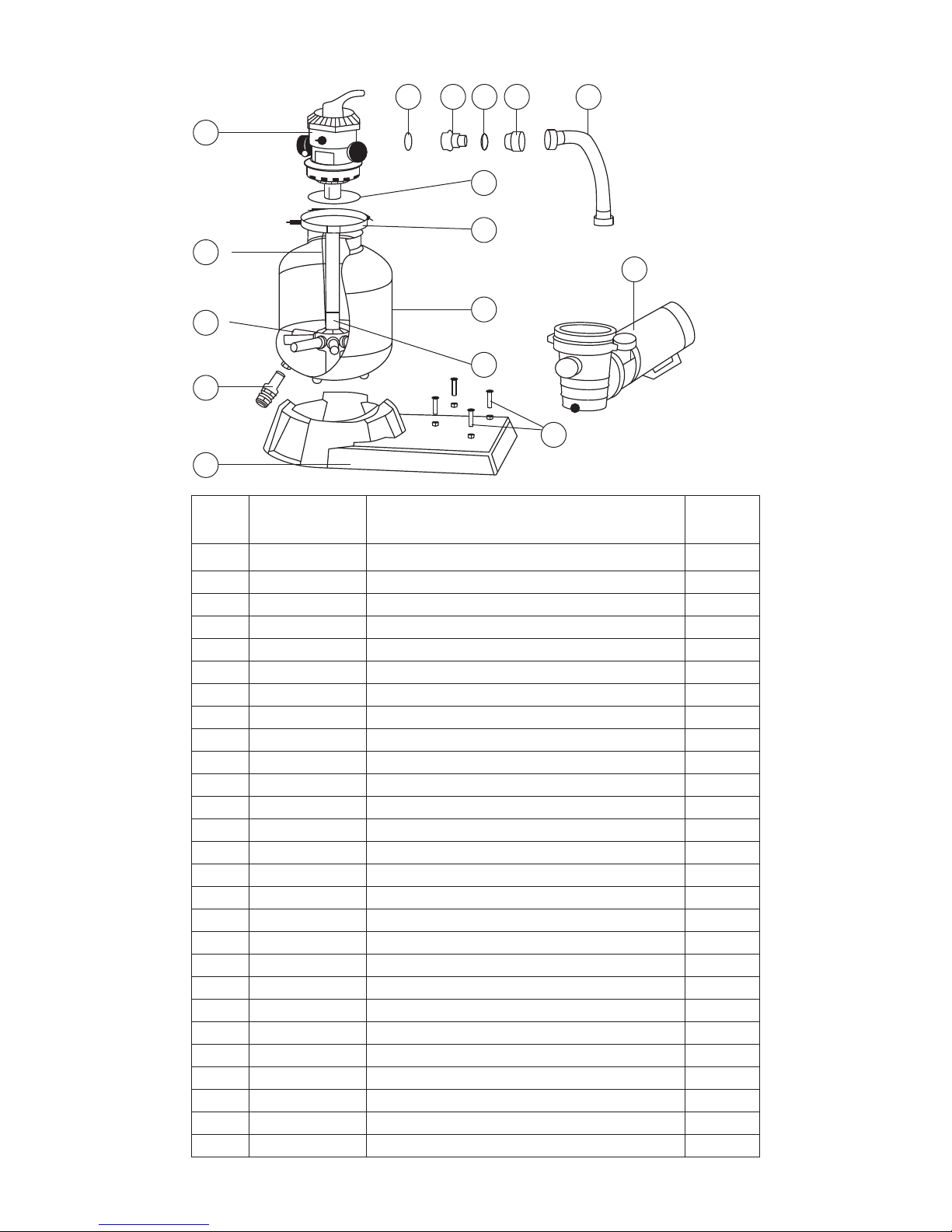
9. To connect the pump to the base, use the screws
from the pump hardware pack. Use the pump
manual to install the and operate the pump.
10. Adjust the valve position. The white pressure hose
connects to the pump output/input valve.
11. The other two connection ends of the valve connect
to the swimming pool and the drain outlet hose.
Installation Notes
1. Make sure the lter is worked under the work
pressure and using a pressure control valve when
the system is using a booster pump.
2. If the pump position is higher than the water level,
it requires to install the back water control valve.
3. If the pump position is lower than the water level,
it requires installing an isolation valve.
4. Minimize the length of pipe and the number of
ttings to minimize friction loss to ensure maximum
efciency.
5. Connect all plumbing to the Multiport Valve taking
care that all joints are glued or tightened securely
to prevent leaking.
6. To prevent breakage and damage to the pump and
Multiport Valve, use only pipe sealants specically
formulated for plastics.
7. Ensure solvents are not excessively applied to
ttings as this could run into O-Rings and create
sealing problems.
8. Do not over tighten ttings or adapters.
InstallationoftheMultiportValve
Top Mount Sand Filters are supplied with a screw
down
Multiport Valve. Supplied with the Multiport Valve are
Flange clamp, screws and O-Ring.
1. Screw the barrel unions onto the threaded ports on
the Multiport Valve.
2. When rotating the Multiport Valve into position
on a Top Mount Filter, leave some leeway for better
alignment of plumbing.
3. Once the Multiport Valve is in position and the
plumbing is aligned, apply the thread tape to the
barrel union thread.
4. Using the roll of Teon tape wrap the Teon tape
around the thread (tail) of the barrel union in a clock
wise direction.
5. Screw the barrel union into the thread of the
Multiport Valve and hand tighten. The barrel union
should be rmly threaded into the Multiport Valve
and there should be no play between the thread.
6. Once you have done this tighten the barrel union
with an appropriate tool until it is tight.
7. Repeat steps until all barrel unions are rmly onto
the Multiport Valve.
8. Glue the plumbing to the Barrel unions and allow
24 hours for glue (solvent) to set before starting
the lter.
9. Test the lter and check for leaks around the
threads. If leaking occurs disconnect plumbing and
repeat the steps 2 to 6 until the leak has stopped.
CHAPTER 4: INITIAL STARTUP OF FILTER
Be sure correct amount of lter media is in tank and
that all connections have been made and are secure.
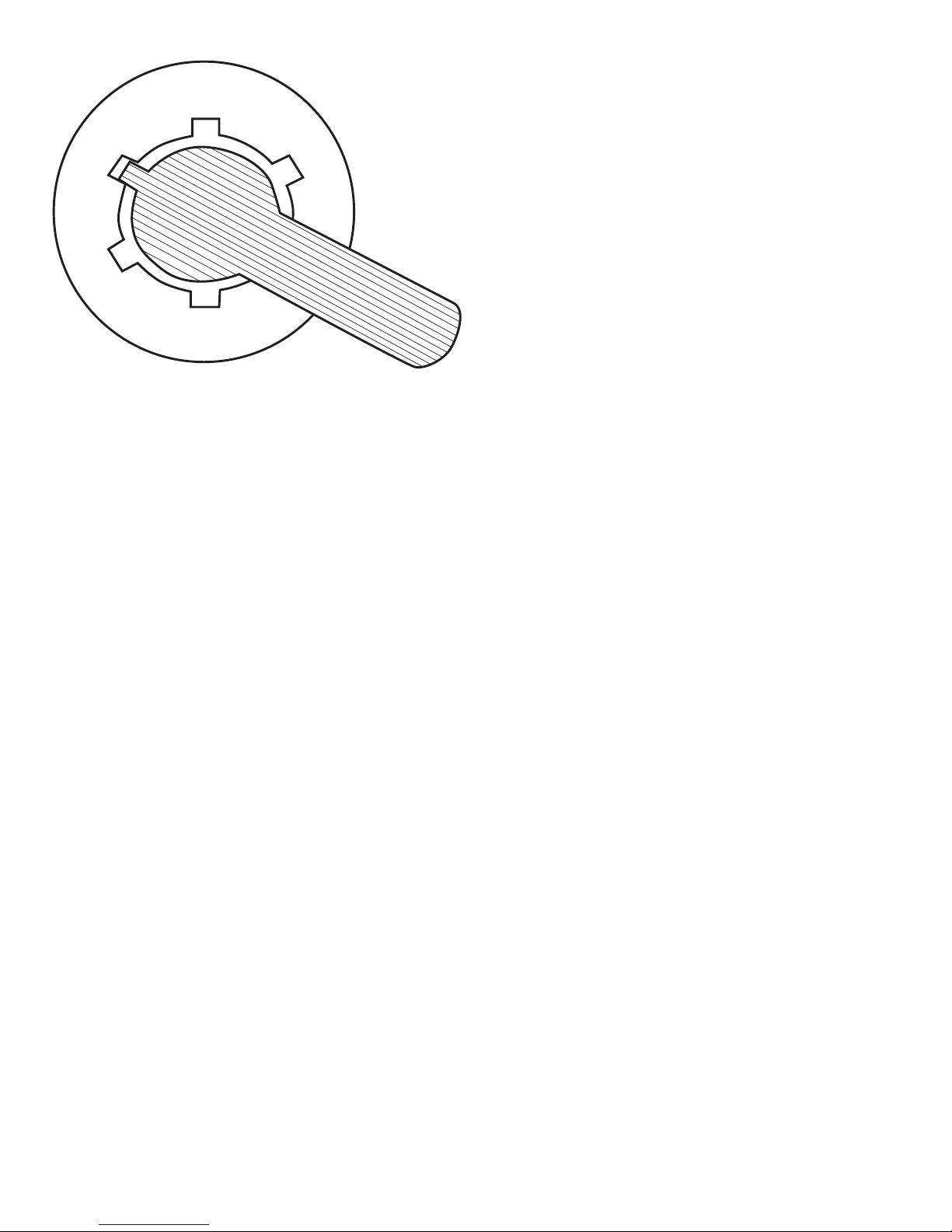
1. Depress Multiport Valve handle and rotate to the
BACKWASH position. NOTE: To prevent damage
to control valve seal, always depress handle
before turning.
2. Switch on the Pump. Open the Inlet Valve allowing
the lter tank to ll with water. CAUTION: All
suction and discharge valves must be open
when starting the pump. Failure to do so could
cause severe personal injury and/ or property
damage. NOTE: If a pump is installed, switch the
pump on and off, instead of closing and opening
the Inlet Valve.
3. Once water ow is steady out the waste line, run
the pump for at least one minute. The initial
backwashing of the lter is recommended to
remove any impurities or ne sand particles in the
lter media.
4. Turn the pump off. Set the Multiport Valve to the
RINSE position. Switch on the Pump. Open the
Inlet Valve until water in sight glass is clear -
approximately 10 to 15 seconds.
5. Switch off the Pump. Close the Inlet Valve, set the
Multiport Valve to the FILTER position and Switch
on the Pump. Open the Inlet. Your lter is now
operating in the normal lter mode.
6. Adjust pool suction and return valves to achieve
desired ow. Check the plumbing and lter for water
leaks and tighten connections, bolts, and nuts, as
required. NOTE: During initial clean-up of the
pool water, it may be necessary to backwash
frequently due to the unusually heavy initial dirt
load in the water.
7. Record the pressure gauge reading (start up
pressure) during initial operation. After a period
of time, the accumulated dirt and debris in the lter
causes a resistance to ow, and the ow diminishes.
The pressure will start to rise and the ow of
water will start diminishing. When the pressure
gauge reading is 8-10 PSI higher than the
initial “Start up” pressure, it is time to backwash
(clean) the lter (see Backwashing). NOTE: To
prevent unnecessary strain on piping system
and valving, always shut off the pump before
switching lter control valve position. To
prevent damage to the pump and lter and
for proper operation of they system, clean
pump strainer and skimmer baskets regularly.

5718 52nd Street Kenosha WI 53144|Orders and Customer Care: 1-866-616-1270|Fax: 1-866-616-1271|HarrisPoolProducts.com
CHAPTER 5: MULTIPORTVALVEOPERATION
1. Filter: Position for ltering the body of water.
Incoming water from the piping system is
automatically directed by the Multiport Valve to the
top of the lter bed. As the water is pumped through
the lter sand, dirt and debris are trapped by the
lter bed, and ltered out. The ltered water is
returned from the bottom of the lter tank, through
the Multiport Valve and back through the piping
system.
2. Backwash: Position for cleaning the lter media.
Water ow is reversed by the Multiport Valve
through the lter bed so that water ow is directed
to the bottom of the tank and up through the lter
bed, ushing the previously trapped dirt and debris
out the waste line.
3. Rinse: Position for ushing the lter system.
The water ow is directed by the Multiport Valve
through the lter bed and out the waste line. This
process settles the lter media bed into place and
ensures any dirt or debris is rinsed out of the lter,
preventing possible return to the Swimming Pool or Spa.
4. Waste: Position for bypassing the lter bed to
Waste. The water ow is directed by the Multiport
Valve straight to the backwash outlet, bypassing the
entire lter bed. This Multiport Valve position is used
to lower the water level or for vacuuming water with
high dirt loads. NOTE: This position is not available
on 4-Way Multiport Valves.
5. Re-circulate: Position for bypassing the lter bed
to the Swimming Pool or Spa. The Mulitport Valve
recirculates water ow directly back to the Pool or
Spa, bypassing the lter. NOTE: This position is not
available on 4-Way Multiport Valves.
6. Closed: Position for closing all ow to the lter.
This position is not to be used with the pump
operating. NOTE:This position is not available on
4-Way Multiport Valves. CAUTION: Operation of
the Multiport Valve or mode selection is to be
always done with the pump switched off.
CHAPTER 6: BACKWASHING
The function of backwashing is to separate the
deposited particles from lter media grains and ush
them from the lter bed. Backwashing is achieved by
reversing the ow of water through the lter bed at a
fairly high ow rate. This high ow rate expands the
lter bed and the water collects the debris taking it to
waste.
ConditionsforBackwashing
Time for backwashing is determined by the following
conditions:
1. The ow rate through the lter bed decreases until
it is insufcient to meet the demand.
2. The removal efciency of the lter bed decreases
to the point where the efuent quality deteriorates
and is no longer acceptable.
3. When the pressure gauge reading is 7.2 PSI
higher than the start up pressure.
4. If the lter is connected to mains water, pressure rise
is not an accurate indicator as mains pressure
tends to uctuate. It is best to rely on the actual ow
rate. NOTE: We recommend that you backwash
a swimming pool sand lter in a residential
installation at least once a month.
ImportanceofBackwashing
The importance of backwashing cannot be overstated.
Dense lter media can become “packed” without
proper and frequent enough backwashing. Debris
will remain trapped and create channeling within the
lter bed. This will result in the lter bed exhausting
early. Moreover, if debris is not ushed from the media
grains, the lter bed will become dirtier and dirtier as
time goes on until the lter operation fails.
Backwashing Instructions
1. Switch off the Pump. Close the Inlet Valve.NOTE:
If a pump is installed, switch the pump on and off,
instead of closing and opening the Inlet Valve.
2. Release the lter’s pressure by loosening Pressure
Release Valve until the Pressure Gauge needle
drops to zero <0>.
3. Retighten Pressure Release Valve.
4. Depress and turn Handle 180º to the BACKWASH
position. In the BACKWASH position, the water
ow is automatically reversed through the lter so
that it is directed to the bottom of the lter vessel,
up through the sand, ushing the previously trapped
dirt and debris out the waste line.
5. Switch on the Pump. Open the Inlet Valve.
Backwash water will ow out through drain pipe.
6. When the backwash water in the sight glass
appears clear, Switch off the Pump. Close the Inlet
Valve.
Backwash
Filter
Close
Waste
Recirculate

5718 52nd Street Kenosha WI 53144|Orders and Customer Care: 1-866-616-1270|Fax: 1-866-616-1271|HarrisPoolProducts.com
7. Depress and turn the handle to the RINSE position.
In the RINSE water ow is directed through the
lter bed and out of the lter through the backwash
outlet. This process settles the lter media bed into
place and ensures any dirt or debris is rinsed out of
the lter, preventing possible return to the pool.
8. Switch on the Pump. Open the Inlet Valve. Rinse
water will ow out through the drain pipe.
9. When the rinse water in the sight glass appears
clear. Switch off the Pump. Close the Inlet Valve.
10. Depress and turn the handle to the Filter position
and Switch on the Pump. Open the Inlet Valve for
normal operation.
CHAPTER 7: MAINTENANCE
The lter media will only require replacement once it
has reached the limits of its designated life. Refer to
the product information of the particular lter media
used. To ensure the maximum life of the selected lter
media, please follow the procedures below.
1. Backwash the lter regularly according to the
instructions set under BACKWASHING.
2. Maintain a correct chemical balance for your pool
or spa’s water. The chemical balance of the water
is a relationship between its pH, Total Alkalinity,
Calcium Hardness and water temperature. The
water must be maintained to the following:
- pH Level: 7.2-7.8.
- Total Alkalinity: 80-175ppm
- Calcium Hardness: 175-300ppm
CHAPTER 8: TROUBLESHOOTING
Above normal or excessive force to operate the
Multiport Valve: Scoring or jamming with foreign
matter or debris. If this condition persists after rinsing,
disassemble the valve to clear. Continued operation
of the valve may result in a non-sealing condition
(damage to spider gasket). This will lead to water loss
to the backwash line or to inefcient ltration.
Dirty Water:
1. Insufcient ltration time.
2. Heavy contaminants or dirt load.
3. Dirty lter, requires backwashing.
4. Air leaking on suction (inuent line).
5. Pump impeller vanes blocked.
6. Insufcient water supply (water level low, blockage).
7. Pump not primed.
8. Incorrect water chemistry.
9. Excessive ow of water for lter size. Foreign
matter or debris forced through lter bed and
through the underdrain.
Filter Media in the backwash:
1. Excessive quantity of media in the lter.
2. Excessive water ow.
3. Incorrect size or grade of lter media.
Filter Media returning to Swimming Pool or Spa:
1. Filter is on recirculate.
2. Verify it is the lter media and not from another
source.
3. Damage to the underdrain laterals.
4. Damage or incorrect t of Multiport Valve are
correct.
5. Incorrect or mixed grades of media in the lter.
Shortltrationcycles:
1. Presence of algae or scale builds up.
2. Check water chemistry.
3. Excessive water ow, check pump size, mains
water ow.
4. Filter blockage. Clean lter media.
CHAPTER 9: SPECIFICATIONS
ITEM FLOW MAXIMUM FILTER MEDIA
NO. RATE PRESSURE AREA REQUIRED
GPM PSI FT LBS
156593 40 50 1.25 100
156594 49 50 2.00 175
156595 50 50 2.80 300

5718 52nd Street Kenosha WI 53144|Orders and Customer Care: 1-866-616-1270|Fax: 1-866-616-1271|HarrisPoolProducts.com
REF PART DESCRIPTION No.
No. NUMBER REQ’D
1 647202701080 Sand Filter Support for 156593, 156594 & 156595 1
2 647304073 Drain Plug 1
3a 647304017 Lateral for 156593 & 156594 8
3b 647306016 Lateral for 156595 8
4a 647304079 Center Pipe for 156593 1
4b 647305071 Center Pipe for 156594 1
4c 647306072 Center Pipe for 156595 1
5a 647304172 Air Release Assembly for 156593 1
5b 647305173 Air Release Assembly for 156594 1
5c 647306173 Air Release Assembly for 156595 1
6a 647304008 Filter Tank for 156593 1
6b 647305008 Filter Tank for 156594 1
6c 647306008 Filter Tank for 156595 1
7 647304072 Flange Clamp 1
8 65431012080 O-Ring 1
9 647304071 6-Way Valve 1
10 65431021080 O-Ring 3
11 647303014 Hose Adapter 3
12 65021005000 Hose Clamp 2
13 647201802001 Adaptor 1
14a 647202772 PVC Hose for 156593 1
14b 647202871 PVC Hose for 156594 1
14c 647202971 PVC Hose for 156595 1
15a 2601 3/4 HP HPP Pump for 156593 1
15b 6578 1 HP HPP Pump for 156594 1
15c 6579 1.5 HP HPP Pump for 156595 1
16 65862026000 Screw M8X35 and Nut M8 4
Above Ground and Inground Sand Filter Systems Item #’s 156593, 156594 & 156595
2
1
3
5
9
a
b
c
a
b
a
b
c
a
b
c
a
b
c
16
4
6
15
14
7
8
10 11 12 13
This manual suits for next models
2
Table of contents
Popular Water Filtration System manuals by other brands

Culligan
Culligan WH-S100-O Installation and operation instructions

Sera
Sera pond UV-C System 55 W manual

BWT
BWT PERMAQ COMPACT 51 Installation and operating manual

Pelican
Pelican PC600 owner's manual

KTI
KTI Keenan MK60SP Installation & user guide

Steinbach
Steinbach Speedclean Comfort 50 ORIGINAL OWNER'S MANUAL

Graf
Graf one2clean+ XXL installation instructions

BWT
BWT bestaqua 6 Fitting and operating instructions

Pall
Pall UR629 Series Service instructions

Aquafine
Aquafine SCD-H Series Installation & operation manual

Pontec
Pontec PondoClear Island 3000 operating instructions

Oase
Oase BioSmart30000 operating instructions