Noble M20 Dual User manual

DNA Line Filter
Dissipative Noise Attenuation Line Filter
Model M20 Dual and M30 Dual
Installation Manual
1.0 Introduction
The DNA product line is designed to reduce the Dirty Electricity (DE) that is commonly found on
AC power lines. This DE is sometimes referred-to by engineers as "noise".
DE is energy (voltages and currents) flowing on the AC power lines that is of a higher frequency
than the 50 or 60 Hz power frequency. DE is found from 100's of Hz to the MHz range.
These DE voltages and currents (flowing on the AC power lines) generate electric and magnetic
fields that radiate into the spaces around the power wiring. It is these fields that people have
reported sensitivity-to. Therefore by using our DNA technology the voltages and currents of the
DE that are riding on the AC power lines are reduced. This then brings about a reduction the the
DE fields that the DE voltages and currents produce.
DE is caused by a wide variety of devices:
•Dirty electricity coming in from the power utility company connection. This dirty electricity
can be from: 1] the non-linearities in the utility company’s infrastructure e.g. transformers.
This type of dirty electricity is often referred-to as “harmonics” 2] broadband dirty
electricity from insulator arcing corona/multipaction in the utility company’s infrastructure
3] poor/corroded connections within the power utility company’s infrastructure 4] dirty
electricity from neighboring residential commercial and industrial properties.
•Dirty electricity from switch mode power supplies that power various electronics which are
connected to the A.C. line including computers off-the-grid power inverters such as solar
array inverters and wind mill inverters office machines uninterruptible power supplies
(UPS) entertainment electronics etc.
•Dirty electricity from switch mode power supplies that are a part of lighting such a LED
1

lights and especially compact fluorescent light.
•Harmonics from traditional power supplies (not switch mode supplies) that power various
electronics noted above.
•Dirty electricity and harmonics from motor speed controls light dimmers and solid state
switches. The latter includes SCR’s and Triacs.
•Harmonics from electrical motors.
•Broadband Dirty electricity from electric arc welders. This is severe intense dirty electricity.
•Dirty electricity from induction heaters. This is severe intense dirty electricity.
•Dirty electricity from certain Radio Frequency (RF) transmitters.
2.0 DNA Products
Many of the DNA products as simple to install and use. They plug into a standard AC outlet. These
are "parallel" devices that provide a path-of-least resistance to the DE. They capture the DE and
turn it into a small amount of heat. These parallel devices work to reduce DE in the frequency
range from roughly 5 kHz to 500 kHz In the lower end of this range (near 5 kHz) these parallel
devices are not performing as well as they perform at higher frequencies – just by the nature of their
design. Examples of these parallel products are: MxDNA RxDNA-V2 PxDNA.
In addition there are true "line filter" products that we offer that provide excellent reduction of DE
at the frequencies of typical inverter switching regulators. Please continue to read for a discussion
on these.
3.0 Alternative Power, A Source f Dirty Electricity
3.1 Dirty Electricity Generation By Inverters
With the growing installation of alternative energy sources in recent years there has been a
significant increase in the DE in residential commercial and industrial settings.
The most common alternative energy sources are photo-voltaic solar arrays and wind mills aka
wind turbines. These devices usually produce direct current (DC). Most or all of the appliances
that the users have will be alternating current (AC) appliances at 50 or 60 Hz (cycles per second).
To accommodate this disparity between the DC available from the alternative source (solar and
wind) and the AC required by the user's appliances a device known as an Inverter is used. It is an
electronic system that switches the DC on-and-off very quickly and thereby generates AC (for use
by the appliances).
These Inverters are typically switch-mode-power-supplies and as a by-product they generate DE.
These Inverters generate 60 Hz AC (in the US) but they do so by switching the DC on-and-off at a
fundamental switch frequency such as 16 Khz. As a result the 60 Hz AC coming from this Inverter
will be "polluted" with the 16 Khz (in this example) switch frequency. In addition there will be
numerous harmonics of the 16KHz present. For example:
2 x 16 KHz = 32 Khz
3 x 16 KHz = 48 Khz
4 x 16 KHz = 64 KHz
2

etc.
These frequencies (16 32 48 64 Khz) are not really intended to be a part of the 60 Hz (in this
example) AC that is provided by the Inverter. They are a a side effect. They represent DE.
3.2 Introduction To Reducing The Dirty Electricity From Inverters
The aforementioned parallel DNA products can be used to reduce the DE from alternative energy
systems specifically the Inverter(s) that are an integral part of the system. In this approach
laboratory test have typically shown a reduction of 10-to-1 of the DE.
In the case of alternative power there can be Inverters that are supplying 1000's of watts of power
from the solar or wind devices. The DE from an Inverter can be considerable and the reduction of a
parallel device (such as a MxDNA RxDNA-V2 PxDNA) may not reduce the DE to a value that is
acceptable to the User (in the residential commercial or industrial setting).
The product that we offer to accomplish a large reduction of the DE from alternative energy systems
is a "line filter" device aka "inline filter". It is the DNA Line Filter.
While the aforementioned parallel products have the considerable convenience of the user simply
"plugging them in" the DNA Line Filter requires a professional electrician to install them.
The DNA-Line Filter will be connected between the Inverter and the users power wiring. The DNA
Line Filter will very effectively reduce the DE from the Inverter.
As a point of comparison the parallel devices (MxDNA, RxDNA-V2, PxDNA) have been tested
and typically reduce the DE 10-to-1.
DNA Line Filter testing shows typical reduction of 500-to-1 at 16 Khz and greater reductions at
higher frequencies.
3.3 Detailed Description of Using DNA Line Filter to reduce Solar/Wind Inverter Dirty
Electricity
Now specifically referring to the application of the DNA Line Filters many solar array / wind
installations in the US are configured with the Inverter supplying 240 VAC with 2 Hot lines and 1
Neutral line. If a DNA Line Filter is being used to reduce DE from the Inverter Output then 2
approaches can be used:
–Use 2 each of the single phase DNA Line Filter products
–Use 1 each of the dual phase DNA Line Filter products
Detailed connection diagram are included in the next major document section 5.0
Not all solar/wind installations in the US are 2 phase (2 Leg). In some cases there is a single phase
power circuit usually 5 KW or less. In thse cases a single phase DNA Line Filter is used.
3

3.4 Using DNA Line Filter To Reduce Dirty Electricity From The Grid
The Bau Biologists of the world have become quite familiar with the phenomenon that significant
DE can present on the incoming power utility lines. This DE can be due to one or more residential
neighbors who are generating DE on their properties industrial neighbors who are generating
DE on their properties or from the utility company itself.
When a residential or industrial neighbor share the same transformer any DE generated within a
property will be present on the utility wiring for all the users of that transformer(s). In other words
one neighbor can pollute many other properties with DE.
In a residential property obvious causes for the generation of DE include solar/wind inverters
HVAC (heating ventilating air conditioning) systems that have variable speed motors pool pumps
portable electric heaters that use pulse width modulation for continuous adjustment of the amount
of heat lamp dimmers compact flourescent lamps most LED lamps/lighting electric stoves that
use pulse width modulation for continuous heat adjustment etc.
In an industrial property the list of DE generating equipment includes most of the residential list
plus dozens and dozens of additional sources – too many to list here.
An example of DE from the utility company there are solar farms that are installed in some
locations by the utility company. These farms can generate massive DE. Unfortunately it is often at
a significantly lower frequency than the typical residential Inverter. Because of this lower
frequency it becomes particularly problematic to mitigate.
3.5 Using DNA Line Filter To Reduce Dirty Electricity From Sources Within Your Porperty
There are a variety appliances/systems within a residence/commercial/industrial property that can
generate a very significant amount of DE. Examples include pool pumps and variable speed HVAC
systems.
These appliances/systems will typically pollute the entire property and also pollute the
neighborhood. A DNA Line Filter can be used with a “reverse connection” to isolate the DE of said
appliance/system and thereby save the property and the neighborhood from the DE.
This reverse connection can be accomplished with a “single” DNA Line Filter or a “dual” DNA
Line Filter.
4

4.0 DNA Line Filter Specifications
Model Numbers
DNA Line Filters are given model designations beginning with M. The number that follows the M
is the maximum AC current rating.
Examples:
M20 = maximum current 20 amperes 50/60 Hz
M30 = maximum current 30 amperes 50/60 Hz
M100 = maximum current 100 amperes 50/60 Hz
etc.
Model Letters
The model number may be followed by a letter if there is more than one model available for that
specific configuration.
Example:
M100a
M100b
The difference between the above-cited models (version a and version b) is the amount of
attenuation (the amount of DE reduction) that is available. In the above-cited example the b model
has 4 times as much attenuation as the a model.
ther Model Descriptors
There are various descriptors that may follow the model number.
Examples:
The descriptor Dual may be used for a model.
Examples:
- A model M20 can accommodate a single AC line phase (aka single Leg) at either 120 VAC or
240/250 VAC.
- A model M20 Dual can accommodate two AC line phases (aka two Legs).
In the US in residental applications a single phase is typically 120 VAC. Appliances that require
high power (e.g. electric clothes dryers electric stoves etc.) will typically be connected with 2
phases (2 Legs) where there is 240 VAC 60 Hz across these 2 phases.
The descriptor NEMA 3R may be used for a model.
NEMA (National Electrical Manufacturers Association) designation is used with the DNA Line
Filter products to indicate certain environmental capbilities. Specifically NEMA 3R is a rain-proof
snow-proof sleet-proof drip-proof enclosure. Note that is all of these environmental conditions the
liquid is coming from above. NEMA 3R is not a “completely sealed” enclosure that will survive
being hosed.
5

Specific Model Specifications Follow
M20 Dual
Maximum Line Voltage: 250 VAC RMS 50/60 Hz.
Maximum Current: 20 amperes AC RMS 50/60 Hz.
Wire gauge range on internal terminal strip: 18 AWG to 4 AWG
Weight: 38 lbs.
M30 Dual
Maximum Line Voltage: 250 VAC RMS 50/60 Hz.
Maximum Current: 30 amperes AC RMS 50/60 Hz.
Wire gauge range on internal terminal strip: 18 AWG to 4 AWG
Weight: 50 lbs.
6

DNA Line Filter Installation Drawings and Images Follow
7

8

9

M20 Dual
10

M20 Dual
11

M30 Dual
12

M30 Dual
13

5.0 DNA Line Filter Installation
5.1 Internal Layout
Installation of the DNA Line Filter is by a professional electrician.
The DNA Line Filter is designed as a wall mount system. External welded plates have mounting
holes to fasten the unit to a wall.
Warning
O-ring sealed holes are provided as pilot holes for chassis punch to cut needed holes for conduit
entry. Remove O-ring bolts as required to use these pilot holes.
It is Very Important to not cause there to be filings, shrapnel, chips, turnings, shavings, etc. in
the chassis.
Do Not drill into the chassis.
Do Not use holesaw or sawzall to cut hole(s) in chassis.
14

6.0 DNA Line Filter peration Notes
6.1 verall peration
The DNA Line Filter has a massive inductor at the core of its design. As with all inductors and
transformers there is some humming and buzzing associated with this device.
Humming and buzzing from an inductor is caused by stray magnetic fields emanating from the
inductor causing the enclosure and accessories to vibrate. In addition Magnetostriction is a second
source of vibration (and thereby humming and buzzing) where the iron core of the inductor
changes shape minutely when exposed to magnetic fields.
The humming and buzzing will depend upon the load current placed on this device. If the
humming/buzzing seems loud then it is likely that there are loads within the facility (residential
commercial industrial) that are drawing current in a pulsed fashion.
An example is a portable electric heater that has a pulse-width-modulation controller to set the
amount of heat being produced.
While most heaters have a simple on-off thermostat to regulate the heat a few heaters have a pulse-
width-modulation scheme and will be turning the power off-on-off-on at the power line frequency
(50/60 Hz). These pulses of current will often be considerable (10 to 12 amperes) and this will
result in loud humming/buzzing in the inductor.
While this humming/buzzing will not affect the filtering performance of the DNA Line Filter the
sound may be objectionable.
In the cases where humming or buzzing does occur and if the user finds humming or buzzing
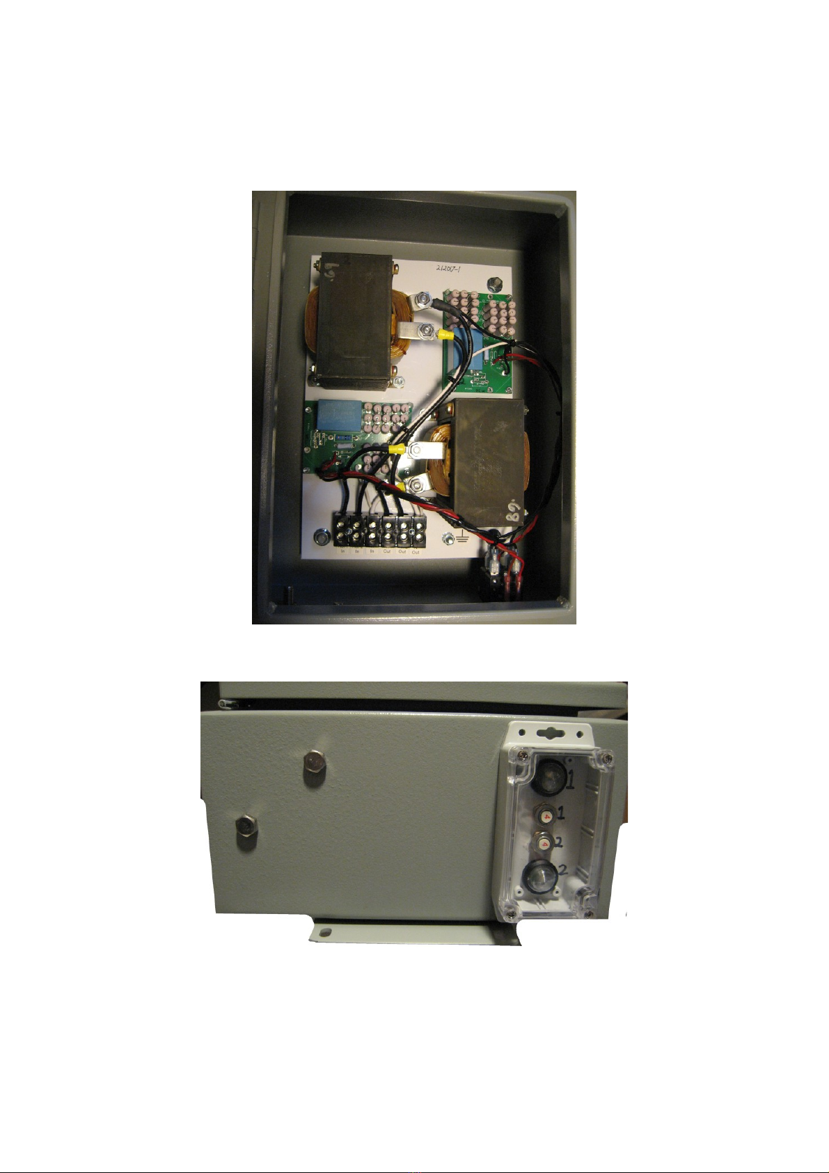
objectionable the DNA Line Filter can be mounted outdoors in a weatherproof enclosure on a
pedestal i.e. not mounted on the building that is occupied. The weatherproof enclosure and pedestal
can be provided by the installing electrical contractor.
It is important to note that the idea of installing the DNA Line filter is to reduce DE in the
facility. A heater that pulses on-off-on-off at the power line frequency, will be generating DE
within the facility and it will be very powerful DE, that likely will extend up to the hundreds
of kilohertz in range. Since this DE is down-stream of the DNA Line Filter, there will be no
attenuation of this internally-generated DE, by the DNA Line Filter. Users who want low DE
in their facility, would be well advised to not use such potent "DE generators" (the pulsed
heater).
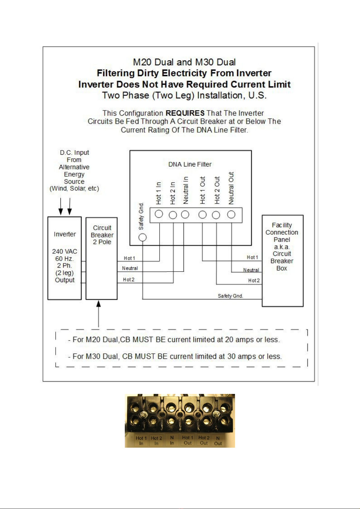
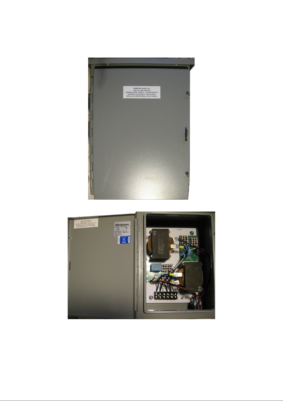
6.2 Internal Circuit Breaker and Panel Lamp
The DNA Line Filter has an internal circuit breaker that interrupts the current flow to the DNA
dissipative electronics if the Dirty Electricity current is too high into those electronics. It is
unlikely that this could ever happen because of the high impedance that the DNA Line filter
inductor presents to the DE. Nevertheless it is a prudent part of a safe design.
The DNA Line Filter front panel lamp is connected on the load side of the aforementioned circuit
breaker. If the circuit breaker is on then the unit is functioning normally and the panel lamp will be
on. If the circuit breaker has cycled off then the panel lamp will be off.
In the case where the lamp is seen to be off then reset the breaker and see if the panel lamp stays
on. If for any reason the circuit breaker continues to cycle off please contact the factory for
troubleshooting information.
Visit us on the web: http://mxdna.com
15
This manual suits for next models
1
Popular Water Filtration System manuals by other brands

Jacuzzi
Jacuzzi JCF150 owner's manual

ZeroWater
ZeroWater ZeroWater owner's manual

Oase
Oase Aquarius Universal Classic 1000 / 12 V operating instructions

SMC Networks
SMC Networks AF20-D Operation manual

Spectra Watermakers
Spectra Watermakers Newport 700C Installation and operating manual

Geekpure
Geekpure RO5-PP10 Maintenance manual