Cosmo LS-1866 User manual

OPERATION MANUAL
AIR LEAK TESTER
MODEL LS-1866
No. LS-1866-941B1-H
1 INTRODUCTION
2 GENERAL INFORMATION
AND SPECIFICATIONS
3 LEAK TESTING OVERVIEW
4 FEATURE SUMMARIES
5 INSTALLATION
6 PARTS IDENTIFICATION
AND FUNCTIONS
7 BASIC OPERATIONS
8 COMPENSATION MODE
(MASTER-PRESET)
9 CALIBRATION (CAL) MODE
10 ORIGINAL (ORG) MODE
11 INTERFACE
12 MAINTENANCE AND
TROUBLESHOOTING
13 APPENDIX


TABLE OF CONTENTS 1
TABLE OF CONTENTS
1
1INTRODUCTION...........................................................................................................................5
1.1 Introduction...............................................................................................................................................5
1.2 Safety Hints ..............................................................................................................................................5
1.3 Notes ........................................................................................................................................................6
2
2GENERAL INFORMATION AND SPECIFICATIONS....................................................................7
2.1 General Information..................................................................................................................................7
2.2 Features ...................................................................................................................................................7
2.3 Specifications ...........................................................................................................................................9
2.3.1 General Specifications ......................................................................................................................9
2.3.2 Test Pressure Gauge........................................................................................................................9
2.3.3 Timer Setting...................................................................................................................................10
2.3.4 Leak Rate Limit ...............................................................................................................................10
2.3.5 Model Classifications ......................................................................................................................10
3
3LEAK TESTING OVERVIEW ......................................................................................................11
3.1 Theory of Leak Test................................................................................................................................11
3.1.1Stage Summary ..............................................................................................................................11
3.1.2 Internal pressure changes of the tested part and master...............................................................12
3.2 Leak Rate Theory and Equations...........................................................................................................12
3.3 Estimating the Test Timer.......................................................................................................................14
4
4FEATURE SUMMARIES.............................................................................................................15
4.1 Master-Preset .........................................................................................................................................15
4.1.1 Theory of Master-Preset .................................................................................................................15
4.1.2 Master-Preset operation .................................................................................................................15
4.1.3 When to execute a Master-Preset process ....................................................................................16
4.2 Leak Calibration (Patented)....................................................................................................................16
4.3 Two-Level Limit Setting and Noise Reduction (NR) Mode.....................................................................17
4.4 Air-Operated Valve Performance and DPS Sensitivity Checks .............................................................17
4.5 Sensor Protection ...................................................................................................................................18
4.5.1 Cleaning pneumatic circuit by Exhaust air blow (DL3) ...................................................................18
4.5.2 External exhaust valve-ready .........................................................................................................18
4.6 CAL ports................................................................................................................................................18
4.7 Clamp Output .........................................................................................................................................19
4.8 Exhaust Interference Prevention ............................................................................................................19
5
5INSTALLATION ..........................................................................................................................21
5.1 Installing the Unit ..................................................................................................................................21
5.1.1Using Quick Mounting Brackets (standard) ....................................................................................21
5.2 Electrical Connection..............................................................................................................................23
5.3 Pneumatic Connection ...........................................................................................................................24
5.3.1 Connection ports.............................................................................................................................24
5.3.2 Pressure sources ............................................................................................................................24
5.3.3 Notes on source air.........................................................................................................................25
5.4 Connecting Master and Tested part .......................................................................................................25
5.4.1 Notes on designing a sealing fixture...............................................................................................25
5.4.2 Master installation ...........................................................................................................................27
5.4.3 Choosing proper connection to the tested part and the master .....................................................28
5.5 Leak Tester Installation Environment .....................................................................................................29
5.6 Procedure for installation and adjustment ..............................................................................................30
6
6PARTS IDENTIFICATION AND FUNCTIONS.............................................................................33
6.1 External Appearance ..............................................................................................................................33
6.1.1Indicators ........................................................................................................................................34
6.1.2 Keyboard.........................................................................................................................................35
6.1.3 Characters Appearing on the Digital Indicator ..............................................................................36
6.1.4 Leak Test Stages ............................................................................................................................37
6.2 Settings and LED Indications .................................................................................................................38
7
7BASIC OPERATIONS.................................................................................................................39
7.1 Turning on Power ...................................................................................................................................39
7.2 Setting a Test Pressure ..........................................................................................................................39
7.3 Test Pressure Gauge Upper and Lower Limit Setting............................................................................39

2 TABLE OF CONTENTS
7.4 Names of Test Pressure Gauge Components (Low · Medium / Vacuum Pressure) ............................ 40
7.4.1 Output Mode .................................................................................................................................. 40
7.4.2 Setting test pressure limits............................................................................................................. 41
7.4.3 Locking the key of the test pressure gauge ................................................................................... 42
7.4.4 Zero reset of the test pressure gauge............................................................................................ 42
7.4.5 Test pressure gauge error display ................................................................................................. 42
7.5 Names of Test Pressure Gauge Components (High Pressure) ............................................................ 43
7.5.1 Output Mode .................................................................................................................................. 43
7.5.2 Setting test pressure limits............................................................................................................. 44
7.5.3 Locking the key of the test pressure gauge ................................................................................... 45
7.5.4 Zero reset of the test pressure gauge............................................................................................ 45
7.5.5 Test pressure gauge error display ................................................................................................. 45
7.6 Unlocking the Keyboard ........................................................................................................................ 46
7.7Switching Remote to/from Manual......................................................................................................... 46
7.8 Start and Stop........................................................................................................................................ 46
7.9 Switching Channels ............................................................................................................................... 46
7.10 Switching Modes ................................................................................................................................... 47
7.11 Measurement Mode............................................................................................................................... 47
7.11.1 Viewing Differential pressure sensor (DPS) offset......................................................................... 47
7.11.2 Viewing raw output of detected differential pressure ..................................................................... 48
7.12 Timer Settings........................................................................................................................................ 48
7.12.1 Viewing........................................................................................................................................... 48
7.12.2 Entry............................................................................................................................................... 48
7.13 Limit Setting ........................................................................................................................................... 49
7.13.1 Viewing........................................................................................................................................... 49
7.13.2 Entry............................................................................................................................................... 49
7.13.3 Limit setting with NR (Noise Reduction) is activated ..................................................................... 49
7.13.4 Two-level limit setting..................................................................................................................... 49
7.14 Unit selection ......................................................................................................................................... 50
7.15 Charge Hold........................................................................................................................................... 50
8
8COMPENSATION MODE (MASTER-PRESET).......................................................................... 51
8.1 Sampling Master-Preset value .............................................................................................................. 51
8.1.1 Preparation..................................................................................................................................... 51
8.1.2 Sampling by manual operation ...................................................................................................... 52
8.1.3 Sampling externally through control I/O port ................................................................................. 53
8.2 Error message during Master-Preset sampling..................................................................................... 53
9
9CALIBRATION (CAL) MODE ..................................................................................................... 55
9.1 Leak Calibration..................................................................................................................................... 55
9.1.1 Preparation..................................................................................................................................... 55
9.1.2 Sampling drift value ....................................................................................................................... 55
9.1.3 Leak calibration using a Leak Master ............................................................................................ 56
9.1.4 Leak calibration using a volumetric-variable Leak Calibrator ........................................................ 56
9.1.5 Go/No Go judgement during leak calibration................................................................................. 57
9.2 DPS Offset Calibration .......................................................................................................................... 57
9.3 DPS Span Inspection ............................................................................................................................ 58
9.3.1 Connecting a Pressure Calibrator.................................................................................................. 58
9.3.2 Changing gain coefficients............................................................................................................. 58
9.4 No-Leak Test ......................................................................................................................................... 59
9.5 No-Leak Test Under Atmospheric Pressure.......................................................................................... 59
1
10
0ORIGINAL (ORG) MODE ........................................................................................................... 61
10.1 ROM Version Information (P-1) ............................................................................................................. 61
10.2 Memory Switch Settings (P-2) ............................................................................................................... 61
10.2.1 How to move to memory switch to be set ...................................................................................... 61
10.2.2 How to change settings.................................................................................................................. 61
10.2.3 Memory Switch Table .................................................................................................................... 62
10.3 Initialization (P-3) ................................................................................................................................... 65
10.3.1 Manufacturer’s settings.................................................................................................................. 65
10.4 Channel Copy (P-4)............................................................................................................................... 65
10.5 Noise Reduction (NR) (P-5)................................................................................................................... 66
10.6 Serial Number Setting ........................................................................................................................... 66
1
11
1INTERFACE ............................................................................................................................... 67
11.1 Control I/O Port...................................................................................................................................... 67

TABLE OF CONTENTS 3
11.2 Channel Selection ..................................................................................................................................70
11.3 Stage Number Output.............................................................................................................................70
11.4 External Signal Timing Charts................................................................................................................71
11.5 Serial Communications Interface ...........................................................................................................72
11.5.1 Interface specifications ...................................................................................................................72
11.5.2 Output formats ................................................................................................................................77
11.5.3 Data format .....................................................................................................................................78
11.5.4 Checksum .......................................................................................................................................80
1
12
2MAINTENANCE AND TROUBLESHOOTING ............................................................................81
12.1 Daily Items to Check and Maintain.........................................................................................................81
12.2 Monthly Items to Check and Maintain ....................................................................................................81
12.3 Annual or Semiannual Inspection Items.................................................................................................81
12.4 Error Messages ......................................................................................................................................82
12.4.1 Errors and Treatment......................................................................................................................82
12.4.2 E-3: Excessive Differential Pressure Sensor Zero-point Shift......................................................82
12.4.3 E-4 Improper test pressure ..........................................................................................................83
12.4.4 E-5: Air-operated Valve Inactive ..................................................................................................83
12.4.5 E-9 Pressurization valve error......................................................................................................83
12.5 Leak Test Troubleshooting.....................................................................................................................84
12.5.1 When No-Go judgements occur consecutively...............................................................................84
12.6 Locating Leaks in Places Other Than the Leak Tester ..........................................................................85
1
13
3APPENDIX ..................................................................................................................................87
13.1 EXTERNAL APPEARANCE...................................................................................................................87
13.2 PNEUMATIC CIRCUIT...........................................................................................................................88
13.2.1 INTELLIGENT I AIR CIRCUIT LS-1866 .........................................................................................88
13.3 Pressure Unit Conversion Table ............................................................................................................89
13.4 Flow Unit Conversion Table ...................................................................................................................89
13.5 CE Marking.............................................................................................................................................89
13.6 Information to Users (FCC Rules) ..........................................................................................................90


1 INTRODUCTION 5
1
1
INTRODUCTION
1
1.
.1
1
I
In
nt
tr
ro
od
du
uc
ct
ti
io
on
n
Thank you very much for purchasing COSMO’s LS-1866 Air Leak Tester. This operation manual provides
information about the LS-1866 Air Leak Tester, including its functionality, operating instructions, and precautions
in handling. Before using the product, read this manual carefully to assure proper handling. After reading, keep
the manual in a safe place for reference.
1
1.
.2
2
S
Sa
af
fe
et
ty
y
H
Hi
in
nt
ts
s
Instructions to abide by for using the product safely without risking physical injury to the user and other persons,
and property damage are given below.
[Explanations of the signs]
Signs
Explanation
WARNING Failure to take or avoid a specific action could result in death or serious physical harm to
the user.
CAUTION Failure to take or avoid a specified action could result in small physical harm to the user
or property damage.
[Explanation of the symbols]
Δ This symbol denotes a warning to alert the user. A specific description of the warning follows.
(Example: Electrical shock hazard)
a) Ground the unit before plugging it into a power source.
The unit, if not grounded, would be liable to electrical
shock hazards. Never connect the grounding
conductor to a gas pipe. Grounding the unit to a gas
pipe could result in fires or electrical shock hazards.
b) If the metallic part of the power plug or any
surrounding area is found dusty, wipe off thoroughly
with a dry cloth. Continued use could result in fires or
electrical shock hazards.
c) Never run the unit from source voltages other than
marked rated. Running the unit from a nonstandard
source voltage could result in fires or electrical shock
hazards.
d) If the unit should be dropped or damaged, switch it off
and disconnect the power plug from the receptacle.
Continued use could result in fires or electrical shock
hazards.
e) Do not apply air pressure beyond the pressure rating
of the unit. Excessive pressure input could cause
catastrophic component failure and/or injury.
f) If foreign matter, such as water and oils, should get
inside the instrument, switch it off immediately and
unplug it from the receptacle. Continued use could
result in fires or electrical shock hazards. Use
particular care when installing the unit in an
environment where water or oils are used nearby.
g) The instrument should be located in a situation where
the power plug can be accessed immediately in case
of an emergency.
h) This unit is not customer-serviceable. Customer
servicing could result in fires or electrical shock
hazards.
i) Replace with a fuse of the same rating as the one that
is built in the unit. Use of a nonstandard fuse could
result in fires or electrical shock hazards.
j) Discontinue using the unit when:
• The unit smokes.
• The unit emits abnormal noises.
• The unit developed problems not covered in the
operations manual.
• The unit cannot be operated as indicated in the
operations manual.
To avoid electrical shock hazards or physical harm,
disconnect the power cable and remove the pressure
source from the unit. Continued use could result in
fires or electrical shock hazards.
WARNING

6 1 INTRODUCTION
a) Do not use the unit in places that are damp, that are
exposed to direct sunlight or that are outside the
temperature range of 5°C to 40°C. Using the unit in
such environments could result in malfunctions or
failures.
b) To avoid damage to the power cable, which could
result in fires or electrical shock hazards, observe
these precautions:
• Do not damage, modify or apply undue force to
the power cable.
• Before servicing the unit, disconnect the power
plug from the receptacle.
• Do not handle the power plug with wet hands.
• When disconnecting the power plug, do not pull
the power cable.
c) Ensure correct cabling. Incorrect cabling could result
in damage to the unit and surrounding hardware.
d) Mount the unit in firm position in a frame capable of
fully sustaining its load. Do not install the unit in a
violently vibrating, sloped or any other rickety place. If
installed in these environments, the unit could fall
down or drop, resulting in physical harm.
e) Do not step on top of the unit or place a container filled
with water, oils/soapy water, or other similar objects on
its top. These objects might spill, causing physical
harm, or electrical shock hazard, rust or other
damage.
f) Do not disassemble the unit. If disassembled, the unit
could malfunction, resulting in physical harm or
electrical shock hazards.
g) Do not install or remove the tubing with the product
connected to an air pressure source. It could result in
physical harm.
Wear a safety goggle to protect your eyes.
h) When a leak test is completed, unclamp the tested
part after the unit has completely exhausted. Residual
pressure could result harm.
i) When carrying the unit, hold it by the bottom to keep it
from dropping. If dropped, unit could be damaged or
caused result in breakage or physical harm.
j) When packing the product for shipment, remove its
projections, such as rear panel-mounted filters and
regulators, and wrap it with cushioning material as a
whole to guard against damage during transit.
k) Wipe out the unit lightly with a dry and soft cloth for
maintenance. When the unit is with heavy dirt, dilute
the neutral detergent with water, soak the cloth in the
detergent, squeeze the cloth, and wipe the dirt out.
Organic solvent should not be used.
l) Put on steel-toe boots when transferring the product
for shipping, installation, dismantling. Neglecting it
could result in physical harm by dropping the product.
m) Handle the product according to the instructions in this
operation manual or the protection feature equipped
with the product will be compromised.
1
1.
.3
3
N
No
ot
te
es
s
a) The information in this document is subject to change without notice for the sake of performance or functional upgrades.
b) This document may not be reproduced in whole or in part without prior approval of the publisher.
c) We are not held responsible for the items tested using this unit and the consequences of the tests.
d) To minimize incorrect test results, this unit comes complete with self-check functions to detect certain improper settings
and operations, and internal equipment malfunctions and thus to prevent incorrect judgments from being delivered. The
scope of monitoring by self-checking, however, is limited. Verification of the unit performance and operations using
separately specified apparatus is recommended.
e) This unit performs measurements based on the principle of differential pressure detection, using the master comparison
method. In addition to actual product leakage there are a number of additional variables that can affect test results, the
most common of these are temperature changes, volume changes and system leakage (on either side of the DP
sensor).
f) The user is encouraged to consult us directly (or your dealer) for any questions the user has about using our product.
CAUTION

2 GENERAL INFORMATION AND SPECIFICATIONS 7
2
2
GENERAL INFORMATION AND SPECIFICATIONS
2
2.
.1
1
G
Ge
en
ne
er
ra
al
l
I
In
nf
fo
or
rm
ma
at
ti
io
on
n
LS-1866 is an air leak tester based on a differential pressure method that tests the air tightness of various
parts and products. Air leak tester allows not only enhancing a detection capability but also an automated
detection process. Ideal for professional and industrial use.
Housing a high-sensitivity, high-pressure differential sensor and air-operated valves free from thermal
effects, the unit is built of intelligent air circuitry that makes on various checks during each run of testing,
including valve action and sensor sensitivity checks, to assure exceptional performance and reliability. Its
Master-Preset feature and noise reduction feature support assures enhanced detectability or shorter test
times. Other user conveniences include compatibility with various kinds of tested parts, direct reading of
leak rates, and easy-to-service CAL ports.
2
2.
.2
2
F
Fe
ea
at
tu
ur
re
es
s
a) Master-Preset compensation feature
• This feature compensates the drift errors caused by the volume difference between the tested part
and the master, adiabatic compression effect and change in ambient temperature.
• Cosmo’s patented Master Chamber that is easy to adjust and maintain can be used as a Master
(Reference) to reduce installation cost.
• Suitable measurement for different part can be achieved by executing Master-Preset process.
b) 2 levels of limit settings and Noise Reduction (NR) mode
• Sorts out NG-judged part by magnitude of leakage.
• In NR mode, DET stage is repeated for the rejected parts fell between the two limits to minimize
false rejection good parts.
c) Leak rate unit (mL/min) can be displayed.
• Differential pressure is converted into leak rate by calibration with Leak Master (LM-1B).
d) High-performance differential pressure sensor and Intelligent I Pneumatic Circuit
• Equipped with a differential pressure sensor that is highly sensitive, proof against high pressure
and low volume. The pneumatic circuit is simple yet full function.
• Equipped with air operated valves with high flow capacity, which is free from thermal effect.
• Includes self-cleaning feature to protect sensor from being contaminated with water and oil inside
the tested part.
• The sensor and the valve performance is automatically checked at the end of the each test cycle to
ensure reliability of leak testing.
e) Multi-channel
• 16 different sets of test parameters can be programmed independently. A channel copy feature
eases multi-channel setting.
f) CAL ports
• CAL ports are easily accessible on the front panel for daily sensitivity check using a Leak Master or
a Leak Calibrator. These ports are also convenient for periodic calibration of the differential
pressure and the pressure gauge.
g) Test pressure and Leak limit setting monitoring
• Test pressure is digitally displayed.
• Upper and lower limits of test pressure can be programmed
• Leak limit setting can always be monitored on the sub-panel
h) Serial communication
• The tester can be connected to computer and/or printer through the serial communication port to
maintain and control the test data.
• Use of a multiplexor enables to connect multiple testers to a single computer.

8 2 GENERAL INFORMATION AND SPECIFICATIONS
i) Quick mounting brackets
• Tester can be removed from the machine easily from the front side by using these brackets.
j) Clamp signal
• This tester can control external solenoid valve to drive air cylinder. Use of this feature allows
building a simple and low cost machine system.
k) Fitness to overseas use
• The power inlet can accept 100 to 240 VAC ±10 % at 50/60 Hz single-phased power supply,
100VA max. The standard power cord supplied with the leak tester is rated for 100 to 120.
Special power cord for 125 to 240 VAC is available upon request.
l) Data storage in flash memory
• There is no need of battery replacement because all the test parameters are stored in flash
memory.
m) Channel copy
• Test parameters of a channel can be copied to the another. This makes multi-channel program
easier.
n) Exhaust interference prevention
• When using several leak testers to measure different cavities on the same part simultaneously, this
prevents jumps in the leak tester readout during the exhaust of one of the other testers.

2 GENERAL INFORMATION AND SPECIFICATIONS 9
2
2.
.3
3
S
Sp
pe
ec
ci
if
fi
ic
ca
at
ti
io
on
ns
s
2.3.1 General Specifications
Differential
pressure
Minimum reading
Display range (Guaranteed)
Sensor range
Sensor proof pressure
Reading accuracy *1
Standard: 0.1 Pa
Standard: ±999 Pa
Standard: ±2000 Pa
5 MPa
±2.5% of rdg ±1Pa for range above 50Pa, ±2Pa for 0-50Pa range
(within guaranteed accuracy range)
Leak rate reading range
0.00 to ±999mL/min (floating point)
Leak rate limit setting range
HI (Work), LO (Master)
Differential pressure unit reading: 0 to±999 Pa
Flow rate unit reading: 0.01 to ±999 mL/min
Number of channels
16 (0 to 15 ch)
Timer
Setting range
0 to±999.8s (infinite 999.9 setting)
Resolution
0.1s
Power supply
100 to 240 VAC ±10 % at 50/60 Hz single-phased power supply, 70
VA max
Test pressure source
Clean air sufficiently higher than the test pressure. Be sure to
connect regulator to eliminate fluctuation of plant air.
Pilot pressure source
Clean air regulated from 400 to 700 kPa
Tubing port inner diameter
Rc (PT) 1/4 (Pressure source, Work and Master ports)
6mm one-
touch joint (Pilot pressure for M, L range is connected to
pressure source by 6mm tubing) (Pilot pressure port)
Control I/O port
Current-sink Open collector Outputs: DB-37P Male connector
Communications functions
Serial communication port (can be switched to printer format)
Operating temperature
5 to 40°C
Storage temperature
-20 to 70°C
Ambient humidity
80 % RH or less, no dew condensation
Weight
M, L, V : 6.3 kg H10, H15 : 8.1kg
Standard components
Pressure regulator, Oil mist separator (except Vacuum pressure type)
Air filter regulator for pilot pressure, Clamp signal connector
Standard accessories
and components
Power cord (withstandability 125VAC, 3 m), Quick mounting
brackets, Control I/O connector,
Inspection record and Operations
manual, Traceability related documents
Optional accessories
5 m power cord, Power cord (withstandability 240 VAC), Leak Master,
Fitting for CAL port and Master Chamber
*1 For the option D4: DPS 10kPa, the reading accuracy is ±5% of rdg ±0.01 kPa. However, ±0.02 for 0.2
kPa or lower..
2.3.2 Test Pressure Gauge
Upper and lower limit setting of digital pressure gauge
Test pressure
pressure range
Proof pressure
Setting resolution
L (Low)
0 to 100.0 kPa
500 kPa
0.1 kPa
M (Medium)
0 to 1.000 MPa
1.5 MPa
0.001 MPa
M10 (High)
0 to 1.000 MPa
1.5 MPa
0.001 MPa
M15 (High)
0 to 1.998 MPa
4 MPa
0.002 MPa
V (Vacuum)
0 to -101.3 kPa
500 kPa
0.1 kPa
Display digits: 3 1/2 digit LED display (Sampling period 5 times/sec)
Display accuracy: ± 2 % F.S. ±1 digits or less (under ambient temperature 25 ± 3°C)
10 2 GENERAL INFORMATION AND SPECIFICATIONS
2.3.3 Timer Setting
Accuracy: Setting ± 1 digit
Setting range: 000.0 to 999.8 s (999.9 s for infinity)
Timers can be set at the user's discretion between 0 and 999.8. A timer setting of 999.9 represents an
infinite timer value. A stage whose timer is set to 0 will be skipped.
Maximum and minimum settings
Stage
Symbol
Minimum
Maximum
Notes
Charge delay
DL1
0.1
999.8
Charge
CHG
0.0
999.8
*1
Balance delay
DL2
0.1
999.8
Balance
BAL
0.1
999.8
Detection
DET
0.1
999.8
End delay
DL3
0.0
999.8
Set to 0.0 s for the high-pressure model (H15).
End
END
0.2
999.8
*1 When memory switch 24 is set to 0, the maximum value of the CHG timer is 6000.0.
When a value of 6001.0 or greater is set, the timer value is infinite.
When a value of 1000.0 or greater is set, the digits following the decimal point are truncated.
2.3.4 Leak Rate Limit
1) HI and LO limit settings for Balance (BAL) and Detection (DET) stages
Differential pressure display: 0 to ±999 Pa (standard: 2000 Pa DPS range)
0.01 to 9,99 kPa (option: 10 kPa differential-pressure sensor range)
Leak rate display: 0.01 to ± 999 mL/min (floating point)
2) HIH and LL limit settings for DET stage
Set to somewhere between +10 and +90% of the HI and LO limits of the DET stage.
3) Judgment accuracy
Matches with leak rate readings.
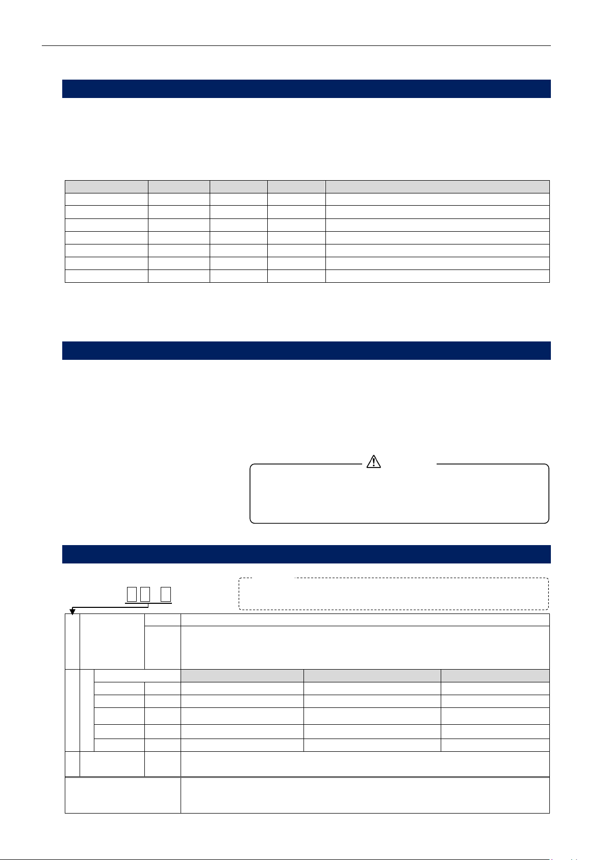
2.3.5 Model Classifications
LS-1866 AB-C
A
Pneumatic
Circuit
A1
Intelligent I Pneumatic Circuit
AS01
Small-volume Intelligent I Pneumatic Circuit
Recommended test condition: Part volume small (50 mL or smaller) and
leak
standard is extremely low. Tester internal volume: 6 mL
B
Test pressure
Pressure range
Digital pressure gauge range
Regulator range
Low
L
10 to 95kPa
0 to 100kPa
5 to 200kPa
Medium
M
50 to 800kPa
0 to 1MPa
0.05 to 0.8MPa
High H10 100 to 990kPa 0 to 1MPa 0.05 to 1.6MPa
High
H15
0.1 to 1.5MPa
0 to 2MPa
0.05 to 1.6MPa
Vacuum
V
-5 to -100kPa
0 to -101.3kPa
-1.3 to -100kPa
C
Options D4
Display of wide differential pressure range.
Differential pressure range 10 kPa (Standard: 1 kPa)
External equipment
available for standard
models
Compatible with external exhaust valve: G-3ME; Remote controller: RC-12B
Limit settings exceeding the DP sensor output range may
cause sensor output saturation during measurement, delivering
an incorrect judgement. Be sure that those limits are within
the range.
CAUTION
The maximum working pressure for the vacuum pressure model
(V) is also constrained by atmospheric pressure conditions.
NOTE
3 LEAK TESTING OVERVIEW 11
3
3
LEAK TESTING OVERVIEW
3
3.
.1
1
T
Th
he
eo
or
ry
y
o
of
f
L
Le
ea
ak
k
T
Te
es
st
t
After a tested part is charged with an air pressure, the resulting change in its internal pressure is measured
to detect a leak. A non-leaking reference part (master) is made available and is charged with a pressure
concurrently with the tested part in Leak Testing. After the air supply is stopped, a high-sensitivity differential
pressure sensor (DPS) detects the pressure change in the tested part resulting from a leak.
3.1.1 Stage Summary
Stages
A
Start
After clamping and sealing a tested part, initiate a start signal.
B Charge (CHG) stage Pressurizes the tested part and the master.
C Balance (BAL) stage
Isolates tested part and master from pressure supply and each
other to let the internal pressure stabilize.
Large leak is detected during this stage as No-Go.
D
Detection (DET) stage
Detects small leaks.
E
Air blow, Exhaust and
End (DL3, END)
Transmits judgment signal, and exhaust pressure inside the
tested part and master from the exhaust port.
Basic Type Pneumatic Circuit
Timing Chart
Solenoid valve DL1
Delay
CHG
Charge
DL2
Delay
BAL
Balance
DET
Detection
DL3
Air blow
Exhaust
END
Exhaust
End
SV1
SV2

12 3 LEAK TESTING OVERVIEW
3.1.2 Internal pressure changes of the tested part and master
In the BAL and the DET stage, the differential pressure
resulting from leaks rises at a constant rate with time. In the
DET stage, the differential pressure sensor (DPS) output is
zeroed through an auto-zero operation before a differential
pressure reading is produced.
3
3.
.2
2
L
Le
ea
ak
k
R
Ra
at
te
e
T
Th
he
eo
or
ry
y
a
an
nd
d
E
Eq
qu
ua
at
ti
io
on
ns
s
When a differential pressure is detected, it can be converted to leak rate unit mL/min by using a conversion
equation derived from Boyle's Law. Using the unit's leak calibration facility removes the need for
calculations based on the conversion equation.
(See Section 4.2. →)
a) Pressure and Volume Relationship
The relationship between pressure and volume is stated in Boyle’s law. Boyle’s law: for an ideal gas,
pressure multiplied by volume is a constant if the temperature is constant. In mathematical form:
PV = constant (where P is in absolute pressure units.)
A leak is measured by a change in pressure. The amount of leakage to atmosphere is calculated and
expressed by the following equation derived from Boyle’s law.
Leakage (ΔVL) = Ve × ΔP / Patm
Where:
Ve: Equivalent internal volume
∆P: Pressure drop due to a leak
Patm: Atmospheric pressure
The definition of internal equivalent volume (Ve) is the volume of air of
the entire Work-side pneumatic circuit at a particular test pressure. It
also includes a diaphragm deformation factor of the DPS. Ve is used
as leak coefficient K(Ve) in the leak rate calculation.
NOTE

3 LEAK TESTING OVERVIEW 13
b) Equivalent internal volume calculation
Differential pressure can be converted into a leak rate by calculating the equivalent internal volume with
the following equation:
Ve = Vw + Vt + [ Ks × { 1 + ( Vw + Vt ) / ( Vm + Vt )} + Kw ] × (101.3 + P ) …………………1
Where:
Ve: Equivalent internal volume [mL]
Vw: Internal volume of the Work side: tested part and the tubing [mL]
Vm: Internal volume of the Master side: master and the tubing [mL]
Vt: Tester internal volume (mL) Vt = 11 mL (Standard pneumatic circuit)
Ks: Change in internal volume of the sensor per unit pressure change [mL/kPa]
Kw: Change in internal volume of the tested part per unit pressure change [mL/kPa]
P: Test pressure [kPa]
If the Master side has the same internal volume as the Work side and
both are so rigid that the test pressure does not physically change their
dimensions, then
Ve = Vw + Vt + 0.01(101.3 + P) …………………2
Where:
Vw = Vm
Ks = 0.005 [mL/kPa] (measured value)
Kw = 0 [mL/kPa]
Ks {(1 + ( Vw + Vt ) / ( Vm + Vt)} + Kw = 2Ks = 0.01 [mL/kPa]
c) Calculation of a Leak Rate
If the volume of air that leaked out of a part is known, this can be converted to a leak rate by knowing for
how long (t) the pressure change (ΔP) was measured.
Mathematically this is expressed as follows:
Where:
Q: Leak rate in volume per time [mL/min]
∆P: Pressure drop due to a leak [Pa]
Ve: Equivalent internal volume [mL]
T: Detection time
The LS-1866 uses the above equation for the calculation of the leak rate. Note that the tester uses
standard atmospheric pressure for this calculation. If the tested part is tested under standard pressure,
1.013 × 10⁵Pa, and standard temperature, 20°C, then the tester displays a standard volume per time.
Example: Converting the differential pressure, ΔP = 50 [Pa] under following test condition into leak
rate using formula 2and 3.
Test pressure (P) = 400 [kPa]
Part internal volume (Vw) = 80 [mL] (including tubing) = Vm
DET timer (T) = 3 [s]
Tester internal volume (Vt) = 11 [mL]
Differential pressure during DET stage (ΔP) = 50 [Pa]
Using formula 2,
Equivalent internal volume (Ve) = 80+11+0.01×(101.3+400) 96 [mL]
Using formula 3,
(mL/min)0.95
3
60
101.013
50
96
5
≒×
×
×
Leak rate (Q) = 0.95 [mL/min]
T
60
10013.1
P
VeQ5×
×
∆
×=
3
Tester internal volume,
Vt, including CAL port
1) Standard: 11 mL
2) AS01 : 6 mL

14 3 LEAK TESTING OVERVIEW
3
3.
.3
3
E
Es
st
ti
im
ma
at
ti
in
ng
g
t
th
he
e
T
Te
es
st
t
T
Ti
im
me
er
r
a) Required measurement timer increases under the following conditions:
• Test pressure is rather high.
• Internal volume of the tested part is large.
• Surface area of the tested part is small
• Leak specification is small.
• Pressure deformation of the part and/or the clamp seal occurs
• Part temperature is different from the ambient temperature.
b) Setting CHG and BAL timers
Generally, a longer CHG timer reduces the ratio of noise presence in the DET stage, contributing to
better measurement accuracy. Set the timers with reference to the general timer ratios, suggested
below and the Table E).
General timer ratios: CHG timer :BAL timer = 3 :1
In setting a CHG timer at installation and adjustment, first run a leak test with a sufficiently long CHG
timer setting. Then, start sampling data by gradually reducing the CHG timer to find out the shortest
CHG and BAL timers in which compliance data gets stabilized in the vicinity of zero.
c) Limitation on the BAL timer setting
A long BAL timer and a large leak limit setting during BAL initiates the DET stage without a large leak
being detected in this stage. In this case, the differential pressure exceeds its LIMIT before the DET
timer ends, resulting in a DPS output saturation. Further, when Leak Master differential pressures are
sampled to establish an equivalent internal volume (leak coefficient), too long a BAL timer can produce
a differential pressure past the measuring range, inhibiting measurement.
Too short a BAL timer, on the other hand, can give rise to differential pressure variations arising from
valve action as errors. Generally, a BAL timer between 1 and 5 seconds is recommended.
d) Setting the DET timer
Typical recommendation for the DET timer is from 2 to 10 seconds and those for the limit setting are
from ±10 to ±100 Pa in differential pressure terms. It is important to make the ratio of the CHG timer
as high as possible to the extent permitted by the limited measurement timer and to avoid indiscriminate
increases in the BAL and DET times. Even a short DET timer can provide a high degree of
detectability.
e) General guidelines for the setting of CHG and stabilization times
(0.01 to 0.1 MPa) (0.1 to 0.6 MPa)
The graph above does not include DET timer. DET timer varies
depending on the leak specifications.
NOTE

4 FEATURE SUMMARIES 15
4
4
FEATURE SUMMARIES
4
4.
.1
1
M
Ma
as
st
te
er
r-
-P
Pr
re
es
se
et
t
4.1.1 Theory of Master-Preset
The measured pressure change in a leak test typically contains both the true leakage and drift errors due to
adiabatic compression and change in the ambient temperature. The pressure change due to leak remains
consistent over time, while the drift errors tend to decrease over time until completely stabilized. The below
graph, Differential pressure change when DET timer is extended shows this. The Master-Preset uses the
drift (Master-Preset value) calculated from the differences in characteristics between drifts and true leakage
to compensate for the leak test data for better detection accuracy
(See Section 8 →).
4.1.2 Master-Preset operation
1) Master-Preset value calculation
The Master-Preset operation is executed by using an actual tested part. In this stage, D1 is measured
in the same measurement time as in a regular leak test. Then, the STB stage (stability time) is
initiated to equalize the pressure of the tested part and that of the master with each other through CHG
until drifts virtually no longer exist, when D2 is measured. The drift value (Master-Preset value) can be
determined by subtracting D2 (leak differential pressure) from D1 (drift value - leak differential pressure).
Master-Preset Value = D1 – D2
where
D1: measured leak rate value in DET (1)
D2: measured leak rate value in DET (2)
2) Compensation using a Master-Preset value in a leak test
Because the value that is detected in a regular leak test is equal to D1 shown above, a precise reading
of the leak rate can be provided by subtracting the Master-Preset value from DET value ΔP for
conformance judgement.
D = ΔP – Master-Preset Value
where
D: Differential pressure after compensation
∆P: Differential pressure detected in the DET stage

16 4 FEATURE SUMMARIES
4.1.3 When to execute a Master-Preset process
Master-Preset process is recommended under one of the following conditions:
1) Production part changeover
For production lines that produce multiple part models, each model should be assigned to a specific
leak tester channel. Therefore, a Master-Preset process is required on the new channel immediately
after the model changeover. Master-Preset is also required when switching parts with different volume
and/or test pressure in a same channel.
2) When test parameters such as test pressure and/or timer settings are changed.
3) When test environment changed
4) When No-Go judgments occur consecutively
The seals in the fixture may be damaged in this case, assuming that production line is unlikely to
produce consecutive defects. Since the test result of a Master-Preset process shows almost true
leakage, it would help in determining if these No-Go judgments are from leaks or from fluctuations due
to drift.
4
4.
.2
2
L
Le
ea
ak
k
C
Ca
al
li
ib
br
ra
at
ti
io
on
n
(
(P
Pa
at
te
en
nt
te
ed
d)
)
To obtain a volumetric leak rate, mL/min, the relationship between the pressure change caused by a leak
and the volume of leakage from the part must be known. The Leak Calibration feature gives a known leak
to the Work-side pneumatic that creates a measurable differential pressure in order to measure its
equivalent internal volume. The definition of internal equivalent volume (Ve) is the volume of air of the
entire Work-side pneumatic circuit at a particular test pressure. It also includes a diaphragm deformation
factor of the DPS. Ve is used as leak coefficient K(Ve) in the leak rate calculation.
Once equivalent internal volume is measured, the differential pressure detected in the leak test DET stage
can be displayed in mL/min (See Section 9.1. →).
a) Measuring equivalent internal volume using a Leak Master
Leak calibration is normally carried out using a Leak Master (reference leak generator). The
equivalent internal volume is calculated from the Leak Master flow rate and the measured differential
pressure.
b) Measuring equivalent internal volume using a Leak Calibrator
When using a Leak Calibrator to determine an equivalent internal volume, convert the volume change
measured during the DET stage into a volumetric leak rate under the atmospheric pressure by using the
following equation and enter it.
(See Section 9.1.4. →)
Where:
Q: Value to input in mL/min (Leak rate corresponding to the volume
change)
∆V: Volume change (mL)
P: Test pressure (kPa)
T: DET timer
c) Sampling compensation values
It is necessary to measure only the differential pressure due to leak to determine the accurate
equivalent internal volume. To accomplish this, do a leak test with a known non-leaking part prior to
the leak test. The resulting measurement value is noted as a drift, by which the value measured in
leak calibration is compensated.
(See Section 9.1.2. →)
T
60
×
3.101
P+3.101
×VΔ=Q

4 FEATURE SUMMARIES 17
4
4.
.3
3
T
Tw
wo
o-
-L
Le
ev
ve
el
l
L
Li
im
mi
it
t
S
Se
et
tt
ti
in
ng
g
a
an
nd
d
N
No
oi
is
se
e
R
Re
ed
du
uc
ct
ti
io
on
n
(
(N
NR
R)
)
M
Mo
od
de
e
a) Two-level limit setting
This leak tester permits setting a small leak limit (Hi-NG) and a large
leak large leak limit (HH-NG) in the DET stage. In the normal leak
test cycle, nonconforming parts can be screened out according to
the amount of leakage. Limit settings for the master are similar to
those on the tested part.
b) Noise reduction (NR)
If the NR feature is enabled, HH-NG is set as a noise reduction limit and the range between HH-NG and
Hi-NG is taken as an uncertain judgement area. If the leak rate detected in the DET stage falls in this
range, a longer stability time is allowed to cancel the noise interference before the leak rate is
redetected.
This feature is useful where there is a high percentage of noise presence caused by temperature or
volume changes. It helps set more critical specifications. A small leak (Lo-NG) and a large leak
(LL-NG), and the NR feature can be set as limit settings on the master as on the tested part. Master
Pre-set is not effective from the second test.
4
4.
.4
4
A
Ai
ir
r-
-O
Op
pe
er
ra
at
te
ed
d
V
Va
al
lv
ve
e
P
Pe
er
rf
fo
or
rm
ma
an
nc
ce
e
a
an
nd
d
D
DP
PS
S
S
Se
en
ns
si
it
ti
iv
vi
it
ty
y
C
Ch
he
ec
ck
ks
s
Air-operated valve malfunction or DPS sensitivity degradation can lead to serious measurement errors. In
order to prevent such failure the sensor and air-operated valve performance is automatically checked at the
end of the each test cycle to ensure reliability of leak testing.
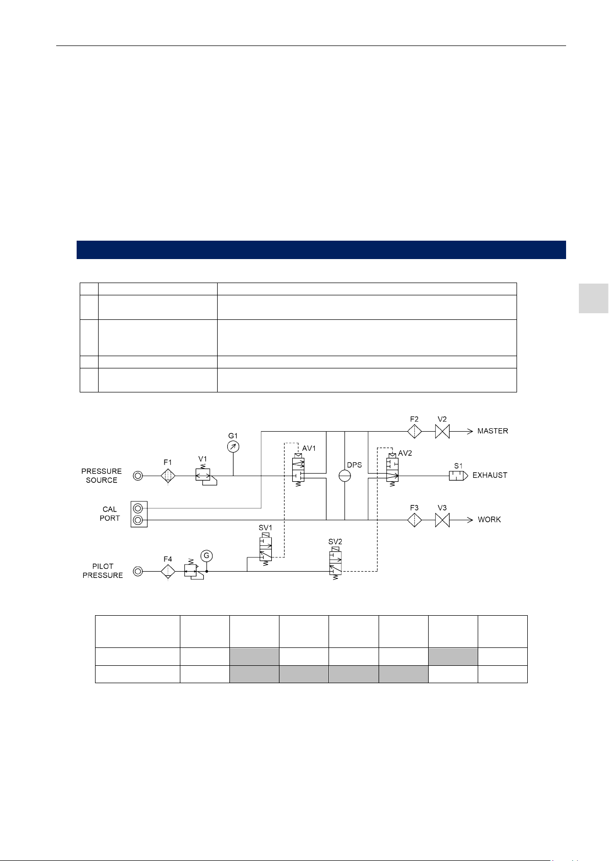
a) Intelligent I Air Circuit (Function Type A)
Air is supplied and air is exhausted from the master and the tested part simultaneously during DL3
stage (Air blow). If the air-operated
valves are functioning normally, the
orifice difference between the exhaust
ports of the master and the tested part
introduces a pressure difference.
This pressure difference is used to
check the test and the pilot pressure
deterioration and DPS sensitivity
degradation as well as the air-operated
valve performance.
b) Other Circuits: H15
The high-pressure Intelligent Ipneumatic circuit, H15, detect the pilot pressures for the air-operated
valves with pressure switches to check their performance.
Large leaks are detected as failures in the BAL stage.
The stage number output allows for discrimination
among Hi-NG, HH-NG, and BAL-NG.
(See Section 7.13.4 →)
NOTE
High pressure model, H15, omits air blow and
self-check.
NOTE
Low pressure models require an optional orifice.
NOTE

18 4 FEATURE SUMMARIES
4
4.
.5
5
S
Se
en
ns
so
or
r
P
Pr
ro
ot
te
ec
ct
ti
io
on
n
If the tested part contains water or an oil, or if the leak tester is used along with water-immersion test, water
and/or oil may enter the tester from the tested part during exhaust stage causing malfunctioning. The
feature protects sensor from such contamination
4.5.1 Cleaning pneumatic circuit by Exhaust air blow (DL3)
Air blow of DL3 is used to clean the pneumatic circuit and prevent DPS from contaminated by blowing off
water, oils and other foreign matter inside the pneumatic circuit along with self check mentioned in section
4.4. Air blow can be disabled by setting DL3 timer to zero. This feature is not available on the
high-pressure model (H15).
(See Sections 4.4 →) (See Sections 10.2.3 →)
4.5.2 External exhaust valve-ready
Air-operated valve are installed between the tested part and the master and the leak tester to effect external
exhaust. An external exhaust valve unit (G3) is separately required.
The standard leak tester controls the G3.
This feature is not available for vacuum pressure leak tester.
4
4.
.6
6
C
CA
AL
L
p
po
or
rt
ts
s
The front panel contains inspection ports that connect to the
tested part and master measurement systems. Connect a
Leak Master, a Leak Calibrator (volume change method), flow
meter to these ports to make a daily check on leak sensitivity
and carry out leak calibration.
Use of the following standards manufactured by us is
recommended to check the test pressure and differential
pressure on a scheduled basis:
The CAL port connectors leading to both the tested part and
master measurement systems are M10 ×1.5 (O-ring S-12).
The conversion fitting M10-Rc1/4 (option) is used to connect an
instrument other than a Leak Master (LM-1B).
G3-ME
Table of contents
Other Cosmo Test Equipment manuals


