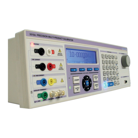
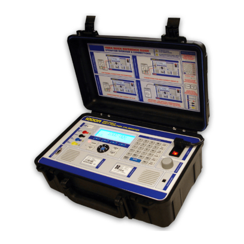
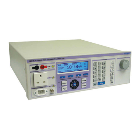
Transmille 4610M User manual

TRANSMILLE 4610M
ADVANCED MULTIPRODUCT
CALIBRATOR
OPERATION MANUAL
V3.01

www.transmille.com
Transmille Ltd 4610M Operation Manual V3.01 - April 2023 2
1.Introduction .................................................. 5
1.1 : Main Features............................................................................................................5
1.2 : Accuracy and Functionality..................................................................................5
1.3 : True Multiproduct Calibration ............................................................................5
1.4 : Retro Fit Options......................................................................................................5
1.5 : USB Interface.............................................................................................................6
1.6 : GPIB (IEEE488) Interface ........................................................................................6
1.7 : Output Connections...............................................................................................6
2.Preparing the Calibrator for Use ................. 7
2.1 : Initial inspection.......................................................................................................7
2.2 : Lifting and Carrying the Calibrator....................................................................7
2.3 : Positioning the Calibrator.....................................................................................7
2.4 : Rear Panel Connections and Controls..............................................................8
2.5 : Setting and checking the Line Voltage............................................................8
2.6 : Power Line Inlet Fuse and rating .................................................................... 10
2.7 : Powering up the calibrator ............................................................................... 11
2.8 : Output Connections............................................................................................ 12
2.9 : Warning and output Overload indications. ................................................ 14
2.9.1 : High Voltage Timeout .......................................................................15
2.9.2 : 30 Amp Temperature Cut-out .........................................................15
3.Operation ....................................................16
3.1 : Safety Warnings .................................................................................................... 16
3.2 : Introduction to Operation................................................................................. 16
3.3 : Front Panel Controls............................................................................................ 17
3.4 : Digital Control........................................................................................................ 19
3.5 : Error Message Indicator...................................................................................... 21
3.6 : Wait Indicator......................................................................................................... 21
3.7 : Touchscreen Interface Functionality............................................................. 22
3.8 : Connection Help Prompts................................................................................. 23
3.9 : Main Menu .............................................................................................................. 25
3.10 : View Configuration............................................................................................ 26

www.transmille.com
Transmille Ltd 4610M Operation Manual V3.01 - April 2023 3
3.11 : Function Menu.................................................................................................... 26
3.11.1 : Function Menu – Voltage...............................................................27
3.11.2 : Function Menu – Current ...............................................................28
3.11.3 : Function Menu – Resistance..........................................................28
3.11.4 : Function Menu – Capacitance......................................................30
3.11.5 : Function Menu – Pulse Width Modulation / Duty Cycle.........31
3.11.6 : Function Menu – PRT / RTD ...........................................................32
3.11.7 : Function Menu – Thermocouple ..................................................33
3.12 : General Settings ................................................................................................. 33
3.12.1 : General Settings – Configure Beeper...........................................34
3.12.2 : General Settings – Specification Display Mode ........................34
3.12.3 : General Settings – Set GPIB Address............................................35
3.12.4 : General Settings – Command Mode ...........................................35
3.12.5 : General Settings – Specifications Display During Warmup...35
3.12.6 : General Settings – Default Negative to Ground State.............36
3.12.7 : General Settings – High Voltage Timeout..................................36
3.12.8 : General Settings - Default Frequency..........................................36
3.12.9 : General Settings - View Error Log.................................................37
3.13 : System Settings .................................................................................................. 37
3.13.1 : System Settings - Set time & Date.................................................38
3.13.2 : System Settings – Change Passcode ...........................................39
3.13.3 : System Settings - Update via USB Service Port..........................40
3.13.4 : System Settings - Hardware error detection..............................40
3.13.5 : System Settings – Restart Calibrator ...........................................41
3.14 : Calibration Menu................................................................................................ 42
3.14.1 : Calibration / Adjustment Mode....................................................44
3.14.2 : Backup Calibration Data................................................................44
3.14.3 : Restore Calibration Data................................................................44
3.15 : Calibrate Touchscreen...................................................................................... 45
3.15.1 : Export Calibration to USB ..............................................................47
3.16 : Special Functions Available Using the ‘Soft’ Keys .................................. 47
3.16.1 : Connecting Output Negative to Line Earth (Ground) .............48
3.16.2 : Selecting front panel control when in Remote Mode..............48
3.17 : Terminal Status LED’s ....................................................................................... 49
4.Connection Diagrams.................................52
4.1 : Voltage - AC/DC .................................................................................................... 53
4.2 : Current Up To 2A - AC/DC ................................................................................. 53
4.3 : Current Above 2A - AC/DC ................................................................................ 54
4.4 : Resistance - 2 Wire Passive / 2 Wire Simulated Variable / 2 Wire Simulat-
ed Variable PRT ................................................................................................ 54

www.transmille.com
Transmille Ltd 4610M Operation Manual V3.01 - April 2023 4
4.5 : Resistance - 2 Wire Compensated Simulated............................................. 55
4.6 : Resistance - 4 Wire Passive / 4 Wire Simulated.......................................... 55
4.7 : Capacitance – Passive & Variable.................................................................... 56
4.8 : Frequency................................................................................................................ 56
4.9 : Pulse Width Modulation (PWM) / Duty Cycle............................................. 57
4.10 : Thermocouple Source...................................................................................... 57
4.11 : Thermocouple Measurement........................................................................ 58
4.12 : Current Simulation Up To 1500A Using EA002 Coil Adapter............. 58
5.Setting Outputs ..........................................60
5.1 : Setting the Output ............................................................................................... 60
5.2 : Adjusting the Set Output Using the Digital Control................................ 60
5.3 : Automatic Display of % or PPM Error and Reference Key...................... 61
5.4 : Range Hold.............................................................................................................. 62
5.5 : Wait Indicator......................................................................................................... 62
5.6 : Low Impedance Loads........................................................................................ 63
5.7 : Setting a DC Voltage Output............................................................................ 64
5.8 : Setting a DC Current Output ............................................................................ 65
5.9 : Setting an AC Voltage Output ......................................................................... 66
5.10 : Setting an AC Current Output ....................................................................... 67
5.11 : Setting 2-Wire Simulated Resistance Output........................................... 68
5.12 : Setting 4-Wire Simulated Resistance Output........................................... 70
5.13 : Setting 2-Wire Simulated Compensated Resistance............................. 71
5.14 : Setting 2-Wire Passive Resistance Output. ............................................... 72
5.15 : Setting 4-Wire Passive Resistance Output ................................................ 74
5.16 : Setting Simulated Capacitance Output ..................................................... 76
5.17 : Setting Passive Capacitance Output........................................................... 78
5.18 : Thermocouple Simulation (Source) Mode................................................ 80
5.19 : Thermocouple Measurement Mode ........................................................... 83
5.20 : Setting Frequency Output.............................................................................. 86
5.21 : Setting Pulse Width Modulation (P.W.M., Mark Space Ratio) Output..
86
5.22 : Setting Simulated PRT (RTD) Output .......................................................... 88
5.23 : Setting DC Current Output using EA002 Coil .......................................... 90
5.24 : Setting AC Current Output using EA002 Coil........................................... 92
6.Guarantee and Service...............................95

www.transmille.com
Transmille Ltd 4610M Operation Manual V3.01 - April 2023 5
1 Introduction
The 4610M calibrator offers the most advanced and up to date means of calibration of a wide
variety of electrical measuring instruments. The 4610M advanced multi product calibrator
provides a fully functional, precision programmable calibration source.
1.1 Main Features
• AC/DC Volts to 1020 V
• AC/DC Current to 30 Amps
• AC/DC Current to 1500 Amps with EA002 50 turn clamp coil adapter (option)
• 2 and 4 wire passive resistance to 1 GΩ
• 2 wire, 2 wire compensated, and 4 wire simulated resistance
• Capacitance to 100 mF (passive and simulated modes)
• Frequency to 1 MHz
• Pulse width modulation / duty cycle
• RTD (PRT) simulation
• Thermocouple source simulation and measurement (°C & °F)
• USB Interface
• GPIB (IEEE488) Interface
1.2 Accuracy and Functionality
The 4610M integrates powerful calibration capabilities using built-in software.
1.3 True Multiproduct Calibration
From one instrument
Designed to provide an accurate cost-effective instrument for the calibration of multimeters,
clamp meters, frequency meters, temperature meters, and capacitance meters.
Designed for use in the laboratory or portable on site calibration, the 4610M calibrator is suitable
for use in a standards laboratory. The 4610M boasts a fast-warm up time combined with
connection to a PC/laptop (via a USB / GPIB interface) allowing for a fast return on investment
and premium accuracy.
1.4 Retro Fit Options
Allows additional functions to be added.

www.transmille.com
Transmille Ltd 4610M Operation Manual V3.01 - April 2023 6
Several internal retrofit options including oscilloscope and power allow the user to select the most
cost-effective solution for the calibration work with the ability to add extra functions at a later
date. External options include current coil adapter for the calibration of clamp meters.
1.5 USB Interface
All functions and outputs of the 4610M calibrator are fully programmable over the USB interface.
The USB Interface presents the calibrator as an RS232 port to the computer. A driver from FTDI is
required if the driver is not detected automatically, which can be downloaded from https://
ftdichip.com/drivers/d2xx-drivers/. Drivers are available for Windows, Linux and Mac
computers.
1.6 GPIB (IEEE488) Interface
All functions and outputs of the 4610M calibrator are fully programmable over the GPIB
(IEEE488) interface.
1.7 Output Connections
The output terminal configuration is designed to match the majority of multimeter input
connections, e.g. volts/ohms, low current and high current eliminating the need for lead changing
during calibration. All outputs are isolated when not in use and an L.E.D. indicator shows the
active output(s).

www.transmille.com
Transmille Ltd 4610M Operation Manual V3.01 7
2 Preparing the Calibrator for Use
2.1 Initial inspection
After shipment the calibrator should be inspected for any signs of external damage. Should
external damage be found contact the carrier immediately. Do not connect a damaged instrument
to the line power as this may result in internal damage. Please retain the original packaging; this
should be used when returning the calibrator for service and recalibration.
2.2 Lifting and Carrying the Calibrator
NOTE :Observe all normal practices for health and safety when carrying heavy items.
The calibrator weighs 23 kg / 51 lbs with most of the weight at the right rear corner. The calibrator
can be carried by one person supporting the underneath, carrying in a horizontal position. The
front handles, fitted as standard, can be used to move the calibrator short distances or to
reposition. A custom carry case with shoulder strap is available if the calibrator is to be regularly
transported - see options list. The calibrator should always be placed down on a firm flat surface
on its base feet. Avoid knocking or banging the calibrator and always place down smoothly.
NOTE :Warning: DO NOT DROP THE CALIBRATOR
This may cause internal damage.
2.3 Positioning the Calibrator
The calibrator can be used free standing on a bench or mounted in a standard rack enclosure. The
calibrator can be operated at any angle; the two front feet have tilt legs for bench operation. For all
installations care must be taken not to cover the ventilation slots underneath or block the fan. A 2”
(5cm) space behind the instrument is also required for line and interface connections.

www.transmille.com
Transmille Ltd 4610M Operation Manual V3.01 8
2.4 Rear Panel Connections and Controls
Connections on the rear panel are provided for Line Power via a 3 Pin Filtered IEC connector
incorporating the Line Fuse and Voltage Selection.
A USB Type B socket is provided for connection to computers for remote control of the calibrator
through software.
A GPIB interface is provided to allow remote control of the 4610M calibrator via GPIB (IEEE488).
2.5 Setting and checking the Line Voltage
NOTE :Warning: The line power cord must have an earth conductor to avoid risk of shock.
NOTE :This instrument must be correctly earthed.
The calibrator has been designed to work from either 100, 120, 220 or 240 Volt line supply. Check
that the voltage selector is set at the correct voltage before connecting the power to the instrument.
Connecting the calibrator to the wrong supply will cause internal damage to the instrument. The
Figure 2-1 : 4610M Rear Panel

www.transmille.com
Transmille Ltd 4610M Operation Manual V3.01 9
calibrator is set for 100V operation in Japan, 120V operation in the USA & Americas, 220V
operation in Europe and 240V operation in the UK.
The set mains voltage can be confirmed by looking at the Mains Inlet on the rear panel. The
selected mains voltage is visible through a small window in the inlet
To change the line voltage, open the voltage selector housing using a blade screwdriver. Gentle
pressure is required to open the cover which contains the voltage selector barrel and the mains
input fuses.
Gently hinge the fuse holder flap forward so that the interior of the inlet is visible, and then
remove the barrel
Figure 2-2 : Mains Inlet, 240V Mains Selection
Figure 2-3 : Position of Flat Bladed Screwdriver to open Fuse Tray
Figure 2-4 : Interior of mains inlet

www.transmille.com
Transmille Ltd 4610M Operation Manual V3.01 10
Rotate so that the desired mains voltage is facing outwards and visible through the hole in the inlet
and replace the barrel. Close the flap using gentle force
2.6 Power Line Inlet Fuse and rating
The power line inlet fuse is located directly above the power inlet within the voltage selector
housing. The correct fuse rating is 3.15A anti-surge for 230V operation and 3.15A anti-surge for
110V operation. Fuses should be rated for 250V Operation regardless of mains voltage input.
To replace the fuse, open the voltage selector housing using a blade screwdriver. Gentle pressure is
required to open the cover which contains the voltage selector barrel and the mains input fuses.
Gently hinge the fuse holder flap forward so that the interior of the inlet is visible, and then
remove both fuse holders (marked with arrows pointing to one side)
Figure 2-5 : Mains Selector Barrel
Figure 2-6 : Mains Inlet, 240V Mains Selection
Figure 2-7 : Position of Flat Bladed Screwdriver to open Fuse Tray

www.transmille.com
Transmille Ltd 4610M Operation Manual V3.01 11
Remove the damaged/incorrect fuse and replace using gentle force into the carrier, and then
replace the fuse holder.
Once both fuses have been checked/replaced, close the flap using gentle force. Take care to ensure
that the mains voltage barrel is still at the correct setting.
2.7 Powering up the calibrator
After connecting line power, the calibrator can be switched on with the line power switch on the
right-hand side of the front panel.
Push the power switch in to power up the calibrator (pushing the power switch again will release
the button and the calibrator will switch off).
Figure 2-8 : Interior of mains inlet
Figure 2-9 : Fuse Replacement

www.transmille.com
Transmille Ltd 4610M Operation Manual V3.01 12
The fan will start, and the front panel display will illuminate indicating power. The display will
show the Transmille logo and state that it is initializing.
After a short delay, during which time the processor performs a self-test of the instrument, the
display will show an output of 000.00000mV DC.
Allow the calibrator to warm up for 30 minutes to obtain full accuracy; the fast start feature of the
calibrator will give approximately 90% of full specifications within 10 minutes. The calibrator has
been designed to be powered up continuously.
• If the calibrator is being used using a remote interface, the control program can be run
once the calibrator has fully initialized.
2.8 Output Connections
NOTE :High voltages may be present on the output binding posts.
NOTE :Ensure calibrator is in the STANDBY condition before changing leads or connections.
Figure 2-10 : Power Switch

www.transmille.com
Transmille Ltd 4610M Operation Manual V3.01 13
NOTE :For voltages greater than 30V AC RMS, 42V AC Peak or 60V DC, the binding posts must
be in the closed position.
ONLY 4mm banana connections should be used for outputs above these voltages.
NOTE :Do not touch exposed metal on banana plugs, spade connections or bare wires. These
outputs may have lethal voltages present
NOTE :Warning: Under no circumstances should any voltage be connected to the calibrator
outputs. Although the output terminals are protected against voltage/current being applied,
repeated application of voltage/current may affect the performance and reliability of the
protection circuitry.
Output binding posts are all low thermal tellurium copper 4mm binding posts. The binding posts
accept 4mm style connectors, as well as spade and bare wire connections when the binding post is
in the open position.
The 4610M calibrator outputs have been designed to allow most multimeters to be calibrated
without changing connections. There are 4 separate ‘sets’ of binding posts that are used for
outputs.
• AC / DC Voltage, 2 Wire Resistance, Capacitance, Frequency, PWM & PRT
• AC / DC Current up to 2A, 2 Wire compensated and 4 Wire Resistance
• AC / DC Current above 2A.
• Earth Terminal
• Thermocouple ‘mini’ socket (thermocouple source and measure)
When an output terminal pair is not active, they are completely open circuit (except for the Earth
Terminal) and isolated from the other outputs. As only one pair is active at any one time (except 4
wire Ohms) they may be combined if required to match the meters input arrangement.
The Earth Terminal is always connected to earth via the earth pin on the IEC connector on the
rear. The earth terminal can be used to connect a floating instrument under test to a common
ground.

www.transmille.com
Transmille Ltd 4610M Operation Manual V3.01 14
NOTE :To avoid ground loops, do not connect the front panel Earth Terminal to ground. The
Earth Terminal is always connected to earth via the rear panel IEC terminal
One example is the configuration of multimeter inputs with a single common low and inputs with
voltage, low and high current. To match this to the calibrator, simply connect the 3 low outputs of
the calibrator together and connect the voltage, low & high current outputs to the appropriate
meter’s inputs. Note that when outputting resistance, the calibrator will use the voltage output
terminals.
A second example is where the meter has separate voltage and current inputs, often using four
wire ohms on both pairs. In this case simply connect the voltage and current outputs to the meter’s
inputs, the calibrator will use both the voltage and current pair on 4 wire ohms.
It is recommended that the voltage and low current leads be of high-quality screened cable with
gold plated 4mm plugs fitted. The cable must be able to withstand 1025 volts AC and have an
insulation resistance greater than 1TΩ to avoid introducing any shunting effect on the high
resistance ranges.
Poor quality test leads will introduce noise, thermal E.M.F. and leakage errors on low voltage &
current ranges and unstable readings on resistance and capacitance outputs. Special test leads are
available from Transmille.
The low output can be connected to line earth or allowed to float as selected - see operation section
of this manual. It is recommended that the low is earthed which will help to reduce noise on high
ohms and low current. If allowed to float with respect to line earth the low must remain within 50
volts of line earth. Outputs are optically isolated from the USB and GPIB interfaces.
2.9 Warning and output Overload indications.
The self-test function of the 4610M calibrator continuously monitors the output of the calibrator
for overload or fault conditions. In the event of the calibrator not being able to drive the load, it
will automatically trip into standby – the Standby indicator will be shown on the screen. The
required drive current being too high on a voltage range, or the required compliance voltage being
too high on a current range causes the ‘standby’ condition. Pressing the Output On key after the
load has been corrected can restore the output.

www.transmille.com
Transmille Ltd 4610M Operation Manual V3.01 15
2.9.1 High Voltage Timeout
As an additional safety feature, the calibrator will automatically return to standby if the output is
on the 200V or 1kV ranges after a set time period (refer to general settings menu - Page 33). The
default setting is 20 minutes, where after the output will switch off and the instrument return to
standby mode.
The remaining time before the output will return to standby is displayed on the screen while the
output is on.
2.9.2 30 Amp Temperature Cut-out
The 4610M calibrator can supply high currents for sustained periods of up to 30A. Above this
value the calibrator will enter a standby / cool-down period until the instrument’s temperature has
reduced. The output amplifier operating temperature is monitored by the micro controller, which
will shut down the output if required. The time before shutting down occurs will vary depending
on the set output current and the load. (see extended specifications). During this shutdown period,
the calibrator will be set to standby with a warning message shown on the display indicating the
temperature limit has been reached. It is safe to reselect the output at any time as the
microprocessor will automatically protect the output amplifier from damage.

www.transmille.com
Transmille Ltd 4610M Operation Manual V3.01 - April 2023 16
3 Operation
3.1 Safety Warnings
NOTE :The information in this section is intended only for qualified personnel. The user must at
all times be adequately protected from electric shock. Qualified personnel must ensure that
operators of the equipment are adequately insulated from connection points.
NOTE :WARNING: This instrument is capable of generating both DC and AC high voltages.
3.2 Introduction to Operation
All functions of the 4610M Calibrator can be controlled from the front panel soft keys, touch
screen interface or controlled remotely by a computer. During remote control the front panel is
‘locked out’, but local control may be resumed by pressing the ‘local’ button - it must be
remembered that this action may disrupt the computer program.
Figure 3-11 : 4610M Front Panel

www.transmille.com
Transmille Ltd 4610M Operation Manual V3.01 - April 2023 17
3.3 Front Panel Controls
The front panel of the 4610M Calibrator utilizes a high-quality custom rubber keyboard with
tactile feel buttons and integrated touchscreen interface. The front panel is therefore sealed against
the ingress of moisture and dirt enabling the calibrator to be used in most working environments
without risk of early failure of the operating buttons. The front panel can easily be wiped clean
with a soft cloth. Care should be taken not scratch the touchscreen interface. All graphics are
‘under printed’ making them rugged and durable.
NOTE :The front panel key buttons are for use with fingers only - do not press the key with hard or
sharp objects e.g. Ball-point pens, pencils, screwdrivers etc. Repeated actions like this will almost
certainly cause the keyboard to fail. (This will not be covered under warranty). Care should also
be taken when transporting the instrument, do not place test leads or other objects on top of the
panel which may come into contact with the display area and cause damage.
NOTE :The touchscreen offers a capacitive touch capability. This means that a stylus is not
required to operate the screen. Hard or sharp objects e.g. Ball-point pens, pencils, screwdrivers
etc. should not be used to enter parameters on the screen. The screen will not operate if a glove is
worn over the operating hand, in cases where this is unavoidable the physical soft keys can be
used to select functions as opposed to utilizing the touchscreen. Please note that the warranty
DOES NOT cover damage caused to the touchscreen by using objects other than fingers to use the
touchscreen interface.

www.transmille.com
Transmille Ltd 4610M Operation Manual V3.01 - April 2023 18
The keyboard is divided into sections to allow easy operation. These sections are displayed in the
table below :
Numerical Keypad
Allows numeric values to be entered.
Multiplier Keys
Mega (M), kilo (k), milli (m), micro(μ)
or nano (n).
Function Keys
Volts (V), Amps(A), Ohms (2 & 4 Wire),
Farads(F), Celsius(°C), & Fahrenheit (°F)
Table 1: Keyboard Functions

www.transmille.com
Transmille Ltd 4610M Operation Manual V3.01 - April 2023 19
3.4 Digital Control
A digital potentiometer allows the ‘highlighted digit’ on the display to be incremented (turning
clockwise) or decremented (turning anti-clockwise). As an output is changed the deviation from
the original value entered on the keyboard is shown in either in% or ppm, depending upon the
magnitude of deviation from the previous set point
Range Up / Range Down Keys
Allow the output to be multiplied /
divided by 10.
Left / Right / Up / Down Arrow Keys
To select the digit to be controlled by the
rotary control.
Output On / Standby Keys
Allow the calibrators output to be
disconnected from the terminals. LED
indicators are incorporated in these
switches to clearly show the output status.
Figure 3-12 : Front Panel Control
Table 1: Keyboard Functions

www.transmille.com
Transmille Ltd 4610M Operation Manual V3.01 - April 2023 20
When the digital control is active allowing the output value to be increased or decreased the
following symbol appears next to the output value.
This enables the control, allowing the highlighted digital to be increased or decrease.
When the screen has two parameters shown at the same time there is a second symbol displayed as
shown below:
Using the touchscreen, touch this symbol will toggle the digital control to the lower display and
highlight the active digit.
The digital control can be pushed to select the highlighted functions on the display instead of
using the button on the screen as shown below.
Figure 3-13 : Single Parameter
Figure 3-14 : Dual Parameters, 1st Parameter
Selected
Figure 3-15 : Dual Parameters, 1st Parameter
Selected
Other manuals for 4610M
2
Table of contents
Other Transmille Test Equipment manuals

Transmille
Transmille 1000 Series Use and care manual

Transmille
Transmille 2100 Use and care manual

Transmille
Transmille 9000 Series User manual

Transmille
Transmille 3000HR User manual

Transmille
Transmille 3000 Series Use and care manual

Transmille
Transmille 1000 Series User manual

Transmille
Transmille 4610M Use and care manual

Transmille
Transmille 4610M Owner's manual

Transmille
Transmille 2100 User manual

Transmille
Transmille 3200B User manual