Hartzell CD15K User manual
2900 Selma Highway, Montgomery AL 36108 USA
PH: +1.334.386.5400 (option 2) FAX: +1.334.386.5450 WEB: www.hartzell.aero P a g e | ii
Maintenance Manual
for Hartzell Engine Technologies LLC. Aircraft Combustion Heater
Models CD15K, CD25K, CD35K, CD45K CD50K, CD55K and CD70K
with P/N’s ending in –1 (dash one series) (Includes Airworthiness Limitations)
MM10001
January 1, 2008
REV. L dated May 21, 2015
FAA Approval has been obtained on technical data in this publication
that affects product type design
NOTE:
Instructions for Continued Airworthiness” as outlined on page 8 are required.
The Airworthiness Limitations Section (Section 7.2.) is MANDATORY.
Before performing service consult www.hartzell.aero for latest revision to this manual.
Changes to the Instructions for Continued Airworthiness will be distributed by way of service
bulletins and service letters. The Airworthiness Limitations section is FAA approved and
specifies maintenance required under section 43.16 and 91.403 of the Federal Aviation
Regulations unless an alternative program has been FAA approved.
Model:
P/N
S/N

2900 Selma Highway, Montgomery AL 36108 USA
PH: +1.334.386.5400 (option 2) FAX: +1.334.386.5450 WEB: www.hartzell.aero P a g e | ii
Congratulations!
You have purchased the world’s highest quality heating system.
Hartzell Engine Technologies LLC (HET) has been servicing heating systems for many years.
Using the latest modern technology, Hartzell Engine Technologies has received FAA approval to
manufacture new TSO-C20 heaters for general aviation aircraft. Installations are available for
most twins and some single engine aircraft. Complete heating systems for aircraft with no prior
combustion heater, are also available.
These units are designed with pilots, passengers, and maintenance personnel in mind. We are
confident upon installation and operation of this heater that you will agree on its excellent
quality. If properly serviced (in accordance with the “Instructions for Continued Airworthiness”
contained in this manual) overall safety and reliability of the system will increase.

2900 Selma Highway, Montgomery AL 36108 USA
PH: +1.334.386.5400 (option 2) FAX: +1.334.386.5450 WEB: www.hartzell.aero
Page | 2
MM10001
Dated 1/1/08
Rev L dated 5/21/15
TABLE OF CONTENTS
TABLE OF CONTENTS . . . . . . . . . . . . . . . . . . . . . . . . . . . . . . . . . . . . . . . . . . . . . . . 2
TABLE OF REVISIONS . . . . . . . . . . . . . . . . . . . . . . . . . . . . . .... . . . . . . . . . . . . . . 4
GENERAL INFORMATION FOR MODEL CD15K, CD25K, CD35K, CD45K, CD50K, CD55K
AND CD70K SERIES COMBUSTION HEATERS:
1. WARRANTY *Must read before proceeding with heater installation, modification or
servicing* . . . . . . . . . . . . . . . . . . . . . . . . . . . . . . . . . . . . . . . . . . . . . . . . . . . . . . . . . . . . . 6
2. INTRODUCTION . . . . . . . . . . . . . . . . . . . . . . . . . . . . . . . . . . . . . . . . . . . . . . . . . . . . . .7
3. SCOPE . . . . . . . . . . . . . . . . . . . . . . . . . . . . . . . . . . . . . . . . . . . . . . . . . . . . . . . . . . . . . . .8
Listing of P/N’s per model series . . . . . . . . . . . . . . . . . . . . . . . . . . . . . . . . . . . . . . . . . . 9
4. DESCRIPTION . . . . . . . . . . . . . . . . . . . . . . . . . . . . . . . . . . . . . . . . . . . . . . . . . . . . . . . . 10
5. CONSTRUCTION . . . . . . . . . . . . . . . . . . . . . . . . . . . . . . . . . . . . . . . . . . . . . . . . . . . . . .11
6. OPERATION . . . . . . . . . . . . . . . . . . . . . . . . . . . . . . . . . . . . . . . . . . . . . . . . . . . . . . . . . . 12
7. (ICA) INSTRUCTIONS FOR CONTINUED AIRWORTHINESS LIMITATIONS
SECTION
7.1 Preflight/Operational check and shutdown procedures 14
7.2 Airworthiness Limitations (MANDATORY) 14
7.3 Flight Manual Supplement (FMS) Sample 15
NOTE: The FMS supplied with your new heater must be inserted in the aircraft flight manual
8. HEATER MAINTENANCE AND SERVICING. . . . . . . . . . . . . . . . . . . . . . . . . . . . . . . 18
8.1. Removal and Installation Procedures 18
8.2. 100hr/Annual Inspection and operational check 19
8.3. 250hr/2yr service and inspection 19
8.4. 1000hr/250hr 4 year service and inspection 20
8.5. 2000hr overhaul 20
8.6. Heater Pressure Decay(PDT) and combustion air pressure switch test 21
8.7. Heater disabling 23
9. HEATER OVERHAUL. . . . . . . . . . . . . . . . . . . . . . . . . . . . . . . . . . . . . . . . . . . . . . . . . . . 24
9.1. Cleaning
9.2. Cleaning Comb Tube and Jacket Assembly
9.3. Heater assembly inspection and testing . . . . . . . . . . . . . . . . . . . . . . . . . . . . . . . . . . . 25
9.4. Reassembly. . . . . . . . . . . . . . . . . . . . . . . . . . . . . . . . . . . . . . . . . . . . . . . . . . . . . . . . . 32
10. TESTING AFTER INSTALLATION OR OVERHAUL. . . . . . . . . . . . . . . . . . . . . . . . . 34
10.1.General 34
10.2.Bench Testing 34
10.3.Operational Test 34
10.4.Determining and setting heat output 35
11. TROUBLESHOOTING . . . . . . . . . . . . . . . . . . . . . . . . . . . . . . . . . . . . . . . . . . . . . . . . . . 37
11.1. Heat Quick Check 37
11.2.Combustion Heater System 39
11.3.Inspection Results 40
11.4.Heater Accessories 41
11.5.Troubleshooting Guide 44

2900 Selma Highway, Montgomery AL 36108 USA
PH: +1.334.386.5400 (option 2) FAX: +1.334.386.5450 WEB: www.hartzell.aero
Page | 3
MM10001
Dated 1/1/08
Rev L dated 5/21/15
TABLE OF CONTENTS
12. FIGURES FOR REFERENCE
TYPICAL COMBUSTION HEATER CUT-AWAY Figure 25. . . . . . . . . 46
TYPICAL TEST SET-UP PRESSURE DECAY TEST Figure 26. . . . . . . . . 47
COMBUSTION AIR SWITCH INSTALLATION Figure 27 . . . . . . . . . 48
TYP. EXHAUST TUBE SEAL SHOWN INSTALLED Figure 28 . . . . . . . . . 49
SPARK PLUG REFERENCES Figure 29 . . . . . . . . . 50
TYPICAL TEST SETUP Figure 30 . . . . . . . . . 51
TYPICAL WIRING SCHEMATICS Figure 31 . . . . . . . . . 52
13. PARTS VIEW OF HEATER ASSEMBLY– TYPICAL Figure 32 . . . . . . . . . 53
14. ACCESSORIES . . . . . . . . . . . . . . . . . . . . . . . . . . . . . . . . . . . . . . . . . . . . . . . . . . . . . . . . . 54
15. PARTS VIEW OF EXPLODED HEATER ASSEMBLY . . . . . . . . . . . . . . . . . . . . . . . . . 56
2900 Selma Highway, Montgomery AL 36108 USA
PH: +1.334.386.5400 (option 2) FAX: +1.334.386.5450 WEB: www.hartzell.aero
Page | 4
MM10001
Dated 1/1/08
Rev L dated 5/21/15
TABLE OF REVISION
REVISION
LETTER
REVISION
DATE
INSERTION
DATE
SECTION
DESCRIPTION
A
3/25/09
3/25/09
Warranty
VII. 4.
IX. A. 11.
IX. H. 1, 3.
IX. H. 1, 3.
Added Teflon notes & purging
delivery line notes.
XIV.
Changed amber light to green on
rotary heat control.
B
9/15/09
9/15/09
Pg 3, 4
Removed model # ref.
VII.E.1
IX.A1
Added recommend tube
replacement note.
XIV.
Changed blue light to amber to
indicate failure.
C
7/27/10
7/27/10
Pg 1
Airworthiness Limitations sect.
corrected from IV.B to VI.B.
D
3/8/11
3/22/11
XV
Removed plug and changed elbow
p/n, added 21794 nozzle holder
option.
E1
7/14/11
7/14/11
Pg 17
Add motor overhaul information.
E2
10/3/11
10/3/11
Pg 1, 3, 7
Added models CD50K & CD70K
E3
10/3/11
10/3/11
Pg 12
Pg 13
Add note about pdt test.
Changed pdt test time from
250hr/2 yr to 250hr/4 yr.
F
2/3/12
2/3/12
Pg 37
Added 4-10 pressurized wiring
schematic.
G
7/24/12
7/24/12
Pg 11
II. iv. O/H temp from 350 deg to
300-450 deg.
Pg 15
VIII.A. Corrected overhaul yr from
5 to 4.
H
9/10/13
9/10/13
Pg 25
XI. B.1.
Corrected “0 to 20” psi for Jet fuel
to “0 to 200”
I
8/1/14
8/1/14
Cover Page
Added models CD50K & CD70K
J
3/26/15
3/26/15
Pg 12, 23,
29, 30, 35
Added torque notes
K
4/16/15
4/16/15
Pg 23
Added “not” to allow lead wire to
twist…..
L
5/21/15
5/21/15
ALL
Reformatted, added more specific
info, clarified procedures, added
warranty page, removed section ref
from ICA’s AL section.


2900 Selma Highway, Montgomery AL 36108 USA
PH: +1.334.386.5400 (option 2) FAX: +1.334.386.5450 WEB: www.hartzell.aero
Page | 6
MM10001
Dated 1/1/08
Rev L dated 5/21/15
1. WARRANTY – *Must read before proceeding with heater installation, modification or
servicing*
1.1. New HET heaters come with 4-yr or 2,000-hr, whichever comes first, full warranties. After 1000-
hrs of heater operation or 4 years (whichever comes first) the pressure decay test and inspection
described in the “Instructions for Continued Airworthiness” becomes mandatory.
1.2. Any warranty work must be pre-authorized in writing by Hartzell Engine Technologies LLC.
1.3. Warranty shipments must be accompanied by proper paperwork reflecting a Warranty
Authorization Number obtained directly from Hartzell Engine Technologies LLC (HET). Return
shipments cannot be accepted without this authorization, HET reserves the right to repair or
replace warrantied items. HET is not responsible for aircraft down-time, lost revenues, customs
or duties. Factory covers ground freight only in the USA if warranty is authorized.
1.4. IN NO EVENT SHALL HARTZELL ENGINE TECHNOLOGIES LLC (HET) BE LIABLE
FOR SPECIAL, INDIRECT, INCIDENTAL OR CONSEQUENTIAL DAMAGE: however
arising, whether in warranty, strict liability, contract, tort, negligence or otherwise, including but
not limited to loss of profits, revenue, loss of total or partial use of the products, facilities,
services, downtime costs, or claims of purchaser for such or other damages whether on account of
products furnished hereunder or delays in delivery thereof, HET liability of any claim shall in no
case exceed the purchase price allowable to the product or part thereof which give rise to the
claim. Notice of claims against Hartzell Engine Technologies LLC must be made in writing
within forty-eight (48) hours of discovery affording HET an opportunity to make a prompt
investigation of surrounding facts and mitigate any damage which might ensure. Should the
responsibility be determined to be Hartzell Engine Technologies LLC a waiver by the purchaser
of any right later to assert such a claim will be required. Any cause of action against Hartzell
Engine Technologies LLC arising out of or relating to the contract or the performance hereof
shall expire unless bought within one year of the time of accrual thereof. The forgoing limited
warranty is exclusive and in lieu of all other warranties expressed or implied, including but not
limited to any warranty of merchantability or fitness for particular purpose.
1.5. NOTICE:
1.5.1. WARRANTY DEPENDANT ON THE FOLLOWING:
1.5.1.1. Balance between combustion air inlet and exhaust is critical. Any modifications to
the heater, combustion air inlet or the exhaust could cause the heater not to run
properly and voids warranty.
1.5.1.2. ANY modification to any HET component without documented permission from the
PAH voids warranty and excludes Hartzell Engine Technologies LLC (company
and/or personnel from any and all liability.
1.5.1.3. Breaking any tamper-proof seal, or introducing Teflon products (Teflon tape,
dope etc.) for use as a fuel sealant voids warranty.
1.6. TO ACTIVATE WARRANTY AND RECEIVE CORE REIMBURSEMENT, you must fill
out and return warranty activation card included with your heater or go online to
www.hartzell.aero/warranty/

2900 Selma Highway, Montgomery AL 36108 USA
PH: +1.334.386.5400 (option 2) FAX: +1.334.386.5450 WEB: www.hartzell.aero
Page | 7
MM10001
Dated 1/1/08
Rev L dated 5/21/15
2. INTRODUCTION:
Aircraft combustion heaters manufactured by Hartzell Engine Technologies LLC are designed
primarily to provide heat to the passengers and crew during ground and/or flight. Additional uses are
de-icing and engine preheating. Heat output generally is from 15,000 to 70,000 BTU.
Heaters are FAA TSO-C20 approved and are designed to use the aircraft fuel (aviation gas or jet) in
both pressurized and non-pressurized aircraft. Both 12 and 24 volt applications are available.
Designated models are CD15K, CD25K, CD35K, CD45K, CD50K, CD55K & CD70K, with a p/n
ending in “-1”.

2900 Selma Highway, Montgomery AL 36108 USA
PH: +1.334.386.5400 (option 2) FAX: +1.334.386.5450 WEB: www.hartzell.aero
Page | 8
MM10001
Dated 1/1/08
Rev L dated 5/21/15
3. SCOPE:
This manual provides maintenance information for aircraft combustion heaters manufactured by
Hartzell Engine Technologies LLC, 2900 Selma Highway, Montgomery,AL 36108 USA.
www.hartzell.aero.
The purpose of this manual is to guide its reader to a thorough understanding and working knowledge
of the Hartzell Engine Technologies “–1” series combustion heater and subsequent components.
While general concepts in operation mentioned herein apply to all aircraft combustion heater makes,
the design and operation of a “-1” combustion heating unit is completely unique to itself. Models vary,
pictures and information are generic and information provided within this manual may not apply to all
models. Please contact Hartzell Engine Technologies for more specific information regarding your
model. In order to achieve continued efficiency and longer Time Before Overhaul (TBO) the
envelope of operation as outlined in this manual must be met.
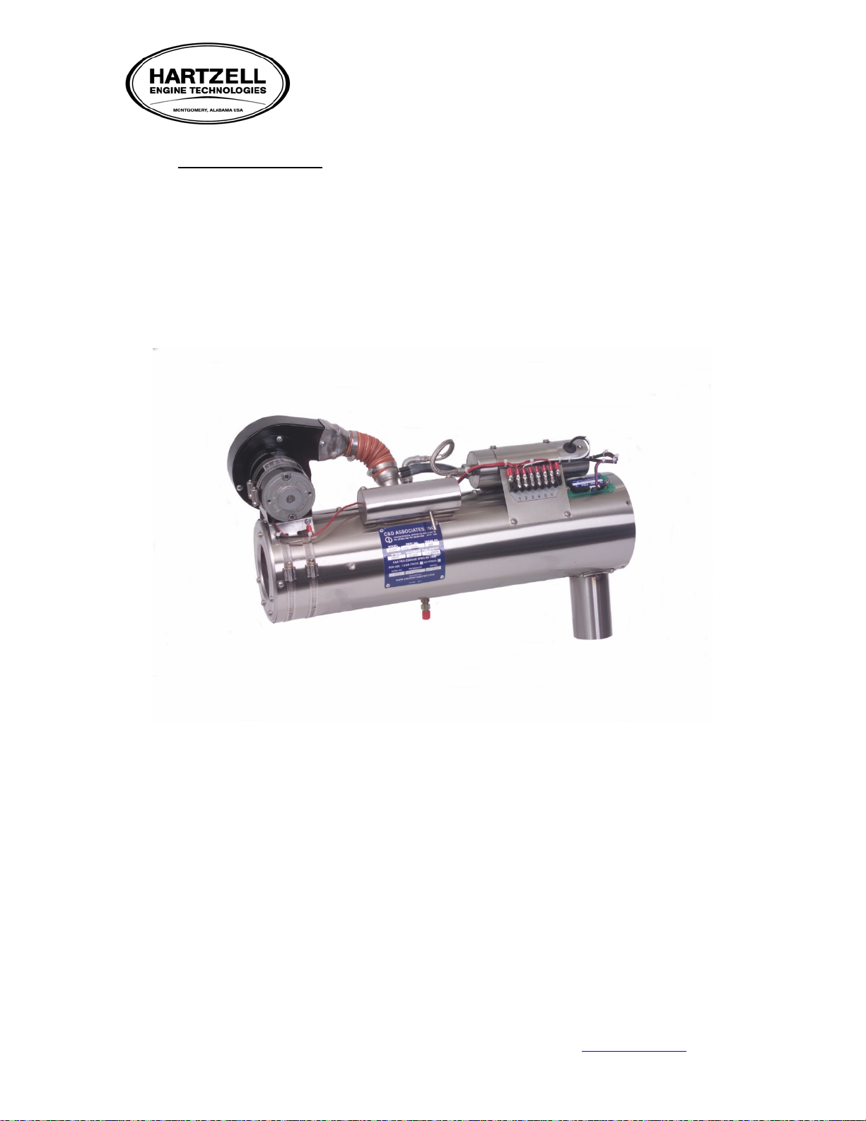
AC&D AIRCRAFT CO MBUSTION HEATER HAS BEEN INSTALLED.
PLEASE FOLLOW THE AIRCRAFT OPERATING MANUAL FOR COMBUSTION
HEATEROPERATING SEQUENCE AN D ASSOCIATES, INC. "INSTRUCTIONS
FOR CONTINUED AIRWORTHINESS" EDITION, DATED 4-4-02 REVI SION
NONE OR LATER FAA APPROVED RE .
FORELIGIBILITY SEE WWW .AIRCRAFTHEATER.COM
COMBUSTION
AIR INLET
FUEL ADAPTER &
FILTER ASSEMBLY
FUEL SOLENOID
OVERHEAT
SWITCH
21528
SCEET HOSE
& CLAMPS
IGNITION
LEAD
HOSE & CLAMPS
IGNITION UNIT
& MOUNT
POWER& COMB.
FUEL PUMP
HEATER HOBBS (OPT)
&/OR SHUTOFF
THERMOSTAT
GROUND
(OPT)
VENTBLOWER
(OPT)
WARNING
OVERHEAT
ADAPTER
COMBUSTION TUBE
& JACKET
REGULATOR
DRAIN
EXHAUST SHROUD
EXHAUST PIPE
CYCLING
SWITCH
MIXER,
HEAD GASKET
FUEL BOX
COMUSTION
BLOWER
ASSEMBLY
NOZZLE,
ORING,
NOZZLE HOLDER
5 BLADE OR
SQUIRREL CAGE
FAN
AIRBLOWER
56 34
56 34
2 1
2 1 NUMBER PLATE
TERMINAL BLOCK
WIRING HARNESS
C&D ASSOCIATES, INC.
FUEL BOX TOP
ROTORY SWITCH
DATAPLATE
COMBUSTION
AIR SWITCH
THERMOSTAT
FAN ENDPLATE
SPARK PLUG
FUEL PUMP
BLOWER
MOUNTING
CLAMPS
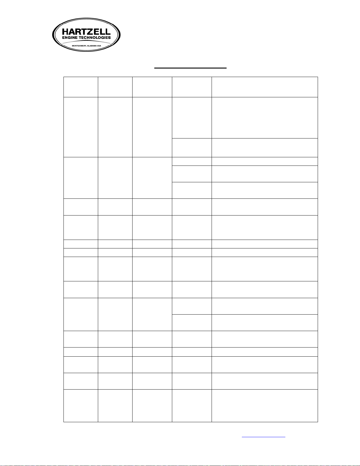
-Heater configurations may differ- (For reference only)
BTU’S LENGTH DIAMETER VDC/AMP
WEIGHT
FUEL
PRESS
AV/JET
MAX.
FUEL
GAL/HR
15-25,000 9-17” 5.50
12VDC/3-18 AMPS
24 VDC/3-14 AMPS
10-25 lbs 7/100 .25 GPH
25-35,000 17-20” 6.00 12VDC/14-20AMPS
24VDC/7-12AMPS
20-30 lbs 7/100 .5 GPH
35-45,000
20-23”
6.00
20-30 lbs
7/100
.65 GPH
45-55,000
21-24”
6.00
20-30 lbs
7/100
.75 GPH
55-75,000
21-24”
6.00
20-30 lbs
7/100
.85 GPH
FIGURE 1

2900 Selma Highway, Montgomery AL 36108 USA
PH: +1.334.386.5400 (option 2) FAX: +1.334.386.5450 WEB: www.hartzell.aero
Page | 9
MM10001
Dated 1/1/08
Rev L dated 5/21/15
LISTING OF P/N’S PER SERIES
* INDICATES JET A APPLICATIONS
CD11000 SERIES
CD11000-1
CD11001-1
CD11002-1
CD11003-1
CD11004-1
CD11005-1
CD11006-1
CD11007-1
CD11008-1
CD11010-1
CD11014-1
CD11047-1
CD11049-1
CD11050-1
CD11214-1
CD11215-1
CD12000 SERIES
CD12003-1
CD12004-1*
CD12006-1
CD12007-1
CD12008-1
CD12009-1
CD12010-1
CD12011-1
CD12012-1
CD12013-1
CD12015-1
CD12016-1
CD12017-1
CD12018-1
CD12022-1*
CD12030-1
CD12031-1
CD12032-1
CD12036-1
CD12039-1
CD12043-1
CD12044-1
CD12059-1
CD12060-1
CD12061-1
CD12064-1
CD12065-1
CD12066-1
CD12067-1
CD12089-1
CD12090-1
CD12091-1
CD12099-1
CD12188-1
CD12189-1
CD14000 SERIES
CD14010-1
CD14019-1
CD14020-1
CD14025-1
CD14026-1
CD14027-1
CD14028-1
CD14041-1
CD14045-1
CD14046-1*
CD14048-1
CD14050-1
CD14055-1
CD14060-1
CD14066-1
CD14067-1
CD14070-1
CD14071-1
CD14072-1
CD14073-1
CD14075-1
CD14076-1
CD14077-1
CD14078-1
CD14079-1
CD14080-1
CD14090-1
CD14125-1
CD14126-1
CD14127-1
CD14152-1
CD14186-1
CD14187-1
CD14188-1
CD14190-1
CD14192-1
CD14193-1
CD15000 SERIES
CD15010-1
CD15011-1 CD15020-1
CD15025-1 CD15030-1
CD50000 SERIES
CD50000-1
CD52002-1 CD52000-1
CD52001-1

2900 Selma Highway, Montgomery AL 36108 USA
PH: +1.334.386.5400 (option 2) FAX: +1.334.386.5450 WEB: www.hartzell.aero
Page | 10
MM10001
Dated 1/1/08
Rev L dated 5/21/15
4. DESCRIPTION
Each heater system generally consists of a combustion chamber assembly, a ventilation air blower, a
combustion air blower, nozzle holder, solenoid valve assembly, spark plug, high-voltage ignition
system, combustion air pressure switch, overheat switch and cycling switch. These components are
combined in a complete assembly. Optional equipment includes thermostat, fuel pump, fuel regulator
and remote shut off valve, heater circuit breaker, controls, and operation indicator lights. The optional
equipment items are provided as separate components since they may be mounted remotely in the
aircraft and subject to customer preferences.
Aviation Gasoline Applications may use an electric fuel pump that provides fuel at 7.0 to 9 PSI for
operation. The heater may be operated from the engine fuel pump, provided the fuel pressure output is
controlled within the operating pressure range of the heater and does not adversely affect engine
operation.
Jet Fuel Applications use an electric fuel pump assembly that fuels through a fuel control system
providing fuel pressure at 105 +5.-0 PSI.
2900 Selma Highway, Montgomery AL 36108 USA
PH: +1.334.386.5400 (option 2) FAX: +1.334.386.5450 WEB: www.hartzell.aero
Page | 11
MM10001
Dated 1/1/08
Rev L dated 5/21/15
5. CONSTRUCTION:
The majority of the heater is manufactured using corrosion resistant stainless steel. The combustion
tube is a welded, gas tight container consisting of the combustion chamber/ radiator assembly with
HET’s exclusive Durakoat coating applied to high wear areas for longer life. The combustion tube is
encased in a stainless steel shroud or 'jacket' assembly. Space between the tube and shroud provides an
area for heat transfer. The ventilation fan, combustion air inlet and fuel feed assembly are located at
one end while the air outlet and exhaust are generally located at the other. On the inlet end of the
combustion tube is the ‘head assembly' where the fuel feed and nozzle assembly that houses the spray
nozzle are attached. Externally mounted is the ignition assembly, fuel solenoid, & wire mounting
terminal board. A combination of mechanical and solid state switches are used to regulate heat and
airflow. These switches also provide safety control for shut down of unit in the event of malfunction.

2900 Selma Highway, Montgomery AL 36108 USA
PH: +1.334.386.5400 (option 2) FAX: +1.334.386.5450 WEB: www.hartzell.aero
Page | 12
MM10001
Dated 1/1/08
Rev L dated 5/21/15
6. OPERATION:
In order for the heater to operate properly, it must have (1) an external power source, (2) ignition, (3)
combustion air, (4) ventilation air and (5) a fuel source. Heat in the combustion chamber or tube is
achieved by burning a fuel to air mixture of proper proportions. Any deviation of this ratio will cause
reduced heat output, poor operation, and shortened TBO. For the following, assume that these are
provided as required.
Properly atomized spray from a specially designed fuel nozzle, a balanced combustion air inlet and
exhaust, coupled with a continuous spark ignition, ensures instant firing and continuous burning under
all flight conditions. Heat is provided by burning this fuel-air mixture in the combustion chamber of
the heater. Jet or aviation fuel is injected into the combustion chamber through the spray nozzle. A
cone-shaped fuel spray mixes with combustion air and is ignited by a spark from the spark plug.
Electric current for ignition is supplied by an ignition unit which converts 12- volts or 24 volts to high-
voltage, oscillating current to provide a continuous spark across the spark gap. A shielded, high voltage
lead connects the spark plug to the ignition assembly. Combustion air enters the combustion chamber
tangent to its surface and imparts a whirling or spinning action to the air. This produces a whirling
flame that is stable and sustains combustion under the most adverse conditions.

2900 Selma Highway, Montgomery AL 36108 USA
PH: +1.334.386.5400 (option 2) FAX: +1.334.386.5450 WEB: www.hartzell.aero
Page | 13
MM10001
Dated 1/1/08
Rev L dated 5/21/15
A
BC
D
D
CONVEX
END DOME
EXHAUST
COMBUSTION
CHAMBER/FLAME TUBE
BAFFLES
HEAT
EXCHANGER
CROSSOVER
MIXER ASSEMBLY
HEAD
ASSEMBLY
FUEL
INJECTOR
REVOLVING
SPARK
FUEL SUPPLY
INCOMING
COMBUSTION
AIR
IGNITOR
JACKET
E
E
HEATED AIR
VENT/FRESH AIR
FIGURE 2
A. Combustion Air Supply. This is provided by way of an external ram air scoop and or a blower
assembly independent of the vent/fresh air supply. Combustion air enters the head assembly, and
then is metered into the mixer chamber.
B. Ignition is supplied via high-voltage oscillating current, this coupled with the igniter design, create
a revolving continuous spark located in the head assembly. This igniter is positioned in the path of
an internal fuel injector designed to atomize the fuel at a pre-determined pressure.
C. This ignited fuel/air mix is then dragged from mixer assembly as additional combustion air
channels through the head assembly into the combustion chamber portion of the liner. The
majority of combustion is created at this point in the combustion chamber or flame tube area.
D. The flame travels full length of the flame tube hitting the end dome, it then doubles back along the
inside wall and on into the outer layer of the heat exchanger. The spent gasses again travel the
length of the tube around a series of baffles then exiting out the exhaust.
E. Air for the ventilation system is picked up via an external ram air scoop and/or a blower assembly
typically mounted on the inlet end of the jacket. Air is forced through the heated external passages
of the combustion chamber. Ventilating air thus comes in contact with the heated cylindrical
surfaces subsequently pushing heated air into the cabin.

2900 Selma Highway, Montgomery AL 36108 USA
PH: +1.334.386.5400 (option 2) FAX: +1.334.386.5450 WEB: www.hartzell.aero
Page | 14
MM10001
Dated 1/1/08
Rev L dated 5/21/15
7. ICA (INSTRUCTIONS FOR CONTINUED AIRWORTHINESS)
Second Edition: Rev E dated 5-21-15
When Hartzell Engine Technologies LLC (HET) heater is installed in an aircraft, the following action is
required. A description of its operational principals, controls, servicing, maintenance, troubleshooting and
testing can be found in the attached MM10001 maintenance manual in the “Table of Contents.”
APPLICATION
Applies to HET Model #CD15K, CD25K, CD35K, CD45K, CD50K, CD55K and CD70K with part
number ending in “–1”. Combustion heaters marked as meeting the standards of FAA TSO-C20, installed
in aircraft certified in any category.
7.1. PREFLIGHT/OPERATIONAL CHECK AND SHUTDOWN PROCEDURE
NOTE: Pilots operating under FAR91 may perform the checks required
7.1.1. Ensure that combustion and ventilation air inlets are free of any obstructions or
constrictions and are not damaged.
7.1.2. Check that the fuel drain line is free of obstructions, constrictions and damage.
7.1.3. Check that the area of the aircraft external skin surface behind the exhaust pipe does not
have indications of excess exhaust slip stream build up.
7.1.4. Perform operational check
7.1.5. Adjust the thermostat or duct limit switch to the minimum setting.
7.1.6. After heater has begun to burn, allow it to cycle a minimum of two minutes to ensure
proper operation in low. Verify medium and high positions also function.
7.1.7. Verify during operation that the exhaust from the heater does not indicate excess smoke.
7.1.8. Prior to shut down, set thermostat to low (cold) and/or fan position. Allow heater to run at
this setting two minutes so as to purge the combustion chamber.
Note: Many “-1” series heaters are equipped with auto-reset overheat switches. If overheat
condition occurs, continue cool down process until automatic reset occurs. (around 100 °F)
7.2. AIRWORTHINESS LIMITATION SECTION (MANDATORY)
The Airworthiness Limitations section is FAA approved and specifies maintenance required under
43.16 and 91.403 of the Federal Aviation Regulations unless an alternative program has be FAA
approved.
AIRWORTHINESS LIMITATION SECTION IS MANDATORY PER FAR 23
PERFORM FOLLOWING CHECKS AS OUTLINED IN THE CIRCUMFERENCE OF THIS
MM10001 MAINTENANCE MANUAL
1. 100 HOUR/ANNUAL OPERATIONAL CHECK (see MM10001 (latest revision) ‘Heater
Maintenance and Servicing’ Section.)
2. 250-HOUR/2 YEAR SERVICE AND INSPECTION (see MM10001 (latest revision)
‘Heater Maintenance and Servicing’ Section.)
3. 1000-HOUR/4 YEAR HEATER INSPECTION AND SUBSEQUENT 250-HOUR/PDT
TEST INTERNAL INSPECTION (see MM10001 (latest revision) ‘Heater Maintenance
and Servicing’ Section.
4. 2000-HOUR/10 YEAR OVERHAUL [to be accomplished in accord with MM10001
(latest revision)]


2900 Selma Highway, Montgomery AL 36108 USA
PH: +1.334.386.5400 (option 2) FAX: +1.334.386.5450 WEB: www.hartzell.aero
Page | 18
MM10001
Dated 1/1/08
Rev L dated 5/21/15
8HEATER MAINTENANCE AND SERVICING
NOTE: Prior to servicing, verify you are using the latest revision of the HET MM10001 Maintenance
Manual. Please consult www.hartzell.aero for latest revisions.
Many hours have been spent to provide the most comprehensive instructions as reasonably possible. It is
strongly recommended that installation and servicing be done by skilled, licensed aircraft mechanics with a
working knowledge of the following:
Fuel lines installed in accordance with AC43.13-1B Chapter 8 section 2 paragraph 8-31.
Electrical installation completed in accordance with AC43.13-1B Chapter 11.
Riveting and metal work in accordance with AC 43.13-1B Chapter 4 Section 4 paragraph 4-57.
The following instructions are outlined and worded with this assumption.
8.1 REMOVAL AND INSTALLATION PROCEDURES
NOTE: Use of Teflon products as a fitting sealer anywhere in a combustion heater fuel system could
contaminate heater fuel nozzle and voids warranty.
NOTE: It is also highly recommended that the fuel system and delivery lines be purged prior to being
connected to heater. This applies to new installations as well as during maintenance involving
any fuel system component. This will greatly reduce the risk of nozzle contamination.
8.1.1 Follow the aircraft manufacturers (OEM) recommendations in the OEM’s maintenance
manual. In most cases the heater operating controls remain the same. If not, operation
will be clarified in the FAA-Approved “Airplane Flight Manual Supplement” provided
for the specific aircraft.
8.1.2 Where deviation from the original heater controls are required the installation instructions
provided with the Hartzell Engine Technologies LLC (HET) heater will address these
changes. Refer to appropriate installation instructions.
8.1.3 For new HET TSO-C20 Supplemental Type Certificate (STC’d) heater kits, the
installation instructions from HET will contain complete procedures for operation and
integrating in the aircraft.
8.1.4 To achieve optimal performance and reliability some new HET FAA-
PMA heater installations require change to the combustion air inlet.
Please follow all instructions specific to your installation closely.

2900 Selma Highway, Montgomery AL 36108 USA
PH: +1.334.386.5400 (option 2) FAX: +1.334.386.5450 WEB: www.hartzell.aero
Page | 19
MM10001
Dated 1/1/08
Rev L dated 5/21/15
8.2 100 HOUR/ANNUAL HEATER INSPECTION AND OPERATIONAL CHECK
NOTE: This inspection must be recorded in accordance with FAR43.9 and maintained as required by
FAR 91.417.
8.2.1 Perform the following checks at the end of 100 hours of heater operation or annual
inspection:
Check that the combustion air and ventilating air inlets are free of any obstructions
or damage of any kind.
Check that the exhaust outlet is free of obstructions or constrictions, is secure, is free
of excessive carbon formations, abnormal stains and/or discoloration, which would
indicate poor heater operation.
Check that the fuel drain lines are free of obstructions, constrictions and damage.
Check the entire length of all fuel lines for security and any visible signs of leakage.
Be sure all joints and shrouds are secure and in good condition.
Check that the heater wiring has no loose connections, cracked or broken wires, or
frayed insulation and is secure at the attachment points.
Check the ignition system for security at the spark plug, making sure there is no
evidence of burning or discoloration of the lead.
Perform the Preflight/operational check to assure correct heater performance.
8.3 250 HOUR/ 2 YEAR HEATER INSPECTION
NOTE: Once the combustion heater has reached 1000 hrs. time in service, pressure decay tests are
required every 250 hours or four years (whichever comes first).
Replace the heater fuel filter by installing filter kit CD21346
Verify the torque of the ignition lead both at the igniter plug (15-20 ft. lbs.) and ignition unit
(12-15 ft. lbs.).
Complete 100hr/Annual inspection and operational check.
This manual suits for next models
6
Popular Heater manuals by other brands

Harvia
Harvia HPCS6U1H Owner's/operator's manual

Luxstar
Luxstar Royal Slim36 Important instructions & operating manual

Helo
Helo 1712-45-1706 Installation and operating instructions

Sunshower
Sunshower PURE XL installation guide

Kogan
Kogan KAHTP1KXXXA quick start guide

CLIMASTAR
CLIMASTAR ETNA instruction manual


Pfannenberg
Pfannenberg FLH 275SLM operating instructions

Calix
Calix Compact L Instructions for use

Chromalox
Chromalox SDRA-RG Installation & operation manual

Crane
Crane EE-6492 instruction manual

Claudgen
Claudgen Heat-Zone Installation, operation and maintenance instructions

Conrad
Conrad 67 15 75 operating instructions