COZY VC201B-D User manual

INSTALLATIONAND
OPERATINGINSTRUCTIONS
P/N 80900 - REV. 06/2015
NATURALGAS VC201B-D VC351B-D VC501B-D VC701B-D VCR351B-D VCR501B-D VCR701B-D
PROPANEGAS VC202B-D VC352B-D VC502B-D VC702B-D VCR352B-D VCR502B-D VCR702B-D
Thisappliance isequipped witha safetycontrol systemdesigned toprotect against
improperventingof combustionproducts.
THIS UNIT IS NOTTO BE INSTALLED IN MOBILE HOMES.
This unit is for residential use only and is not approved for installation in mobile homes, green-
houses, or environments involving dusty, wet, corrosive, or explosive conditions. Such conditions
will invalidate the warranty and may create unsafe conditions.
WARNING: Operationofthisheaterwhennotconnectedtoaproperlyinstalledandmaintained
ventingsystemortamperingwiththeventsafetyshut-offsystemcanresultinCarbonMonoxide
(CO)poisoningandpossible death.
Installation, maintenance, service, troubleshooting and repairs must be performed by a qualified service agency.
MR./MRS. HOMEOWNER, DO NOT attempt any of these procedures yourself as this could expose you to
property damage, personal injury, or loss of life and will invalidate all warranties.
INSTALLER: Leave this manual with the appliance.
CONSUMER: Retain this manual for future reference.
The coating selected to provide longer life to
the heat exchanger may smoke slightly upon
initial firing. Provide adequate ventilation if
this occurs.
RADIANT
FRONT
CLOSED
FRONT
WARNING: If the information in this manual is not
followed exactly, a fire orexplosion may result
causingpropertydamage,personalinjury ordeath.
-Donot storeoruse gasolineorother flammablevapors
andliquidsin thevicinityof thisorany otherappliance.
- WHATTODO IFYOUSMELLGAS:
•Donot trytolightanyappliance.
•Donot touchanyelectrical switch;do notuseany phone
inyourbuilding.
•Immediatelycallyourgassupplierfromaneighbor’s
phone. Followthegassupplier’sinstructions.
•Ifyou cannotreach yourgassupplier,call thefire
department.
-INSTALLATIONAND SERVICE MUSTBE
PERFORMEDBYAQUALIFIEDINSTALLER,
SERVICEAGENCYORTHEGASSUPPLIER.
Thecoating selectedto providelonger lifetotheheat
Gas-Fired Vented
Room Heater

SPECIFICATIONS………………………. 2
INTRODUCTION……………………….. 3
VENTING………………………………... 3 ,4
GASSUPPLY……………………………. 5
LOCATION&SPECIALPRECAUTIONS 5
COMBUSTION&VENTILATIONAIR.... 6
CLEARANCES………………………….. 7
DRAFTDIVERTER…………………….. 7
DOORKNOB…………………………… 7
PILOTADJUSTMENT…………………. 8
RADIANTS&GLASSPANELS……….. 8
BURNERORIFICE&ORIFICECHART.......... 8
PROPERBURNERFLAME.............…………. 9
MAINTENANCE…………………………....... 9
LIGHTINGINSTRUCTIONS……………........ 10
TROUBLESHOOTINGCHART………… 11,12
BLOWERINSTRUCTIONS……………… 13
TSKWALLSTATKIT................................ 14
PARTSDRAWING……………………….. 15
PARTSPRICELIST………………………. 16
WARRANTY……………………………… 18
READCAREFULLYBEFOREINSTALLINGUNIT
These installation instructions are a general guide and do not supersede applicable local codes and ordinances. Before
planning or making the installation be sure it complies with all phases of the local heating code. (Or, in the absence of
local codes, with the latest edition of National Fuel Gas Code, ANSI.Z223.1, or CAN1-B149).
The appliance, when installed, must be electrically grounded in accordance with local codes, or in the absence of local
codes, with the latest edition of National Electrical Code ANSI/NFPA 70, or Canadian Electrical Code CSA-C22.1.
All of the ANSI and NFPA standards referred to in these installation instructions are the ones that were applicable at
thetime the designofthis appliance wascertified. TheANSI standards areavailablefrom the AmericanGasAssociation,
1515 Wilson Blvd., Arlington, VA. 22209.
The NFPA standards are available from the national Fire Protection Association, 60 Batterymarch Street, Boston,
Massachusetts 02110.
Canadian standards are available from International Approval Services, 178 Rexdale Boulevard, Etobicoke, Ontario,
Canada M9W 1R3.
The design of this appliance was certified to comply with the latest edition of ANSI Z21.86 and CSA2.32.
Installer must leave these instructions with the consumer, have them complete, and return the warranty card.
ROOMHEATERSPECIFICATIONS
Your room heater comes packed in a single carton. Before installation, check the rating plate to verify that the Model Number is
correct and that the room heater is equipped for the type gas you intend to use.
TABLEOFCONTENTS
TYPE CONTROL GAS MODEL NUMBERS
CLOSEDFRONT THERMOSTATBULB NATURAL VC201B-D VC351B-D VC501B-D VC701B-D
CLOSEDFRONT THERMOSTATBULB L.P. VC202B-D VC352B-D VC502B-D VC702B-D
RADIANTFRONT THERMOSTATBULB NATURAL N/A VCR351B-D VCR501B-D VCR701B-D
RADIANTFRONT THERMOSTATBULB L.P. N/A VCR352B-D VCR502B-D VCR702B-D
HEIGHT 20” 26” 26” 30”
WIDTH 24” 30” 30” 36”
DEPTH 15-1/4” 15-1/4” 19-1/4” 19-1/4”
INPUT(BTU/HR.) 20,000 35,000 50,000 70,000
GASINLET/OUTLETSIZE 1/2X3/8” 1/2X3/8” 1/2X3/8” 1/2X3/8”
VENTSIZE 3” 4” 4” 5”
CENTEROFVENTTOFLOOR 16-1/2” 21-1/2” 21-1/2” 25-1/2”
NUMBEROFRADIANTS(“VCR”SERIES) N/A 5 5 5
NUMBEROFRADIANTGLASS(“VCR”SERIES) N/A 2 2 2
APPROX.SHIPPINGWEIGHT(“VC”SERIES) 55 LBS. 84 LBS. 112 LBS. 138LBS.
APPROX.SHIPPINGWEIGHT(“VCR”SERIES) N/A 96 LBS. 124 LBS. 150LBS.
*OPTIONALBLOWERMODEL N/A CHB-3 CHB-3 CHB-3
*All 70M Btu units come with blower mounted only.
SPECIFICATIONS
Page 2
The State of Massachusetts requires that installation and service of a gas appliance be performed
byaplumberorgasfitterlicensedintheCommonwealthofMassachusetts.

INTRODUCTION
THISISAGAS-FIRED,GRAVITYVENTEDROOMHEATERTHATWILLOPERATESAFELYANDPROVIDEANEFFICIENT
SOURCEOFHEATWHENINSTALLED,OPERATEDAND MAINTAINEDAS RECOMMENDEDINTHESE INSTALLATION
ANDOPERATINGINSTRUCTIONS. READTHESEINSTRCTIONSTHOROUGHLYBEFORE INSTALLING,SERVICING,OR
USING THISAPPLIANCE. IFYOU DO NOT UNDERSTANDANYPARTOF THESE INSTRUCTIONS, CONSULT LOCAL
AUTHORITIES,OTHERQUALIFIEDINSTALLERS,SERVICETECHNICIAN,THEGASSUPPLIER,ORTHEMANUFACTURER.
VENTING
This heater must be connected to a properly installed and maintained venting system. This heater is equipped with a manual reset
vent safety shut-off device. Pilot burner outage will occur if the heater is not connected to a vent system. Pilot burner outage may
occur due to restriction or blockage in the vent or if connected to a masonry chimney having an area greater than the vent size
shown on Page 2. This appliance should be vented through a properly sized listed type B vent that has been constructed in
accordance with the National Building Code. If a horizontal section of vent is used, it must slope upwards a minimum of ¼ inch per
foot of length.
This heater must not be connected to a vent system being used for wood or coal burning appliances. The use of more than one
appliance per vent system will most likely cause the vent safety shut-off device to shut off the heater due to the cooling of vent
temperatures through the draft diverter of the second appliance. In some situations, the vent safety shut-off may shut down the
heater if a large, unlined, masonry chimney is used. Due to low vent temperatures associated with more efficient heaters it may take
too long to get the vent action going in a chimney before the shut-off device will shut down the heater. If this is the case, we
recommend lining the chimney with the proper size type B vent pipe or type B chimney liner.
WARNING: Do not bypass the vent safety shutoff switch. To do so could expose the consumer to
property damage, personal injury or possible death.
The switch, when activated, will extinguish the burner flame. If the homeowner experiences this problem, the vent system must be
checked and corrected. NOTE: An existing vent that has worked for years may not be adequate for todays design because of
higher efficiency requirements resulting in lower stack temperatures. The following is a list of possible causes and corrective
actions.
POSSIBLECAUSES CORRECTIVE ACTION
1. Blockage in vent pipe 1.A) Check vent pipe for blockage, such as bird nest, wasp nest, twigs, leaves, etc.
1.B) Check that the vent cap is properly installed, not shoved too far down on the vent
pipe.
2. Burner is over firing 2.A) Check the manifold pressure.
2.B) Check the rate, NOTE: This appliance was orificed for elevations up to 2,000 feet.
When installed at higher elevations refer to orifice chart in main burner orifice
section of instructions for proper orifice size and re-orifice accordingly.
3. Improper vent system 3. Correct vent system.
A) Vent too short A) The vent should not terminate less than 5 feet above the drafthood connection. A
gas vent extending through an exterior wall shall not terminate adjacent to the
wall or below eaves or parapets. Also, the top of the vent must be at least 2 feet
above all obstacles within a 10 feet radius, including the roof. See FigureA.
B) Restrictionin vent B) All type “B” vent shall extend in a generally vertical direction with offsets not
system caused by exceeding 45 degrees, except that a vent system having not more than one 60
offsets degree offset may be allowed. Any angle greater than 45 degrees from the vertical
is considered horizontal. The total horizontal run of a vent plus the horizontal vent
connector shall be not greater than 75 percent of the vertical height of the vent.
Any offsets used should be as far above the drafthood as possible to allow the
venting action to begin before any restriction is encountered.
C) Incorrect vent pipe C) Use listed “B” type vent pipe. Do not use transite or any other type of ceramic
pipe for venting. Do not use single wall pipe for vent or vent connector.
4. Loose connections on the 4. Check the connection on both the switch and the gas valve. Tighten if necessary.
Page 3
vent safety wiring harness

VENTING
10’ or Less
2’Min.
3’Min.
Ridge
Chimney
More than
10’ 10’
2’Min. 3’Min.
Ridge
Chimney
Height above any
roof surface
withon10’
horizontally
FIGUREA FIGUREA
Seal around collar
& flashings
Maintain
1”Clearance Support
Laterals
Termination of vent must be
securely guyed or braced if
it extends more than five (5)
feet above roof. See
Termination
diagram
above
Firestop Support
Assembly
VerticalVent
Elbow
Listed
Appl.
Terminate vent
at least 5 ft.
above draft hood
CONNECTINGTHEVENT INTO
AN EXISTING CHIMNEY
SAFE (See “Venting”)
NOTE: Thismayresult
intheventsafetyswitch
shuttingdowntheburner
dependingonsizeand
drawofchimney.
NOT
RECOMMENDED
FIGURE7A
1/4
UNSAFE
Donot
installin
thismanner.
FIGURE7B
RECOMMENDED
Useproper size“B”
pipeorchimneyliner
insidechimney.
FIGURE7C
Page 4

GASSUPPLY
Thisventedroomheatermustbeconnectedtoagassupply
capableof supplyingthe fullrated capacity. Providea1/
8inchN.P.T. pluggedtapping,accessible for test gauge
connection, immediately upstream of the gas supply
connectiontotheappliance. Theminimuminletpressure
inthegassupplypipeshouldbe4.5”w.c.forNaturalGas
and 11.0” w.c. for Propane Gas, “for purpose of input
adjustment”. Themaximuminletpressureinthegassupply
pipe must never exceed 14” w.c. for either Natural or
PropaneGas. Thegassupply piping should besizedin
accordancewithANSI Z223.1NationalFuel GasCode.
The normal manifold pressure should be 3.5” w.c. for
Natural Gas and 10.0” w.c. for Propane Gas.
If the outlet pressure of the gas valve must be adjusted,
thismust bedone bya qualifiedservicetechnicianusing
propertools andinstruments.
Checkall connectionswithsoapy waterfor possiblegas
leaks. Neveruseamatch,candleorother ignitionsource.
Itisrecommendedthatpipecompoundwhichisresistant
to the action of liquefied petroleum gases be used. Do
notuseTeflon tapeorTeflonimpregnated compound.
Theapplianceanditsindividualshutoffvalvemust
bedisconnected fromthe gassupply pipingduring
anypressuretesting of thatsystemat test pressure
inexcess of½psig.
Theappliancemustbeisolatedfromthegas supply
pipingbyclosingitsindividualmanualshutoffvalve
duringanypressure testingofthe gassupplypiping
systemattestpressuresequaltoorless than½psig.
LOCATIONANDSPECIAL
PRECAUTIONS
Duetohigh temperatures the appliance shouldbe
locatedoutof traffic and away fromfurnitureand
draperies.
Childrenandadultsshouldbealertedtothehazards
ofhighsurface temperature and shouldstayaway
toavoidburnsorclothingignition.
Youngchildrenshouldbecarefullysupervisedwhen
theyare in thesame room asthe appliance.
Clothingorother flammablematerialshouldnotbe
placedonor near theappliance.
Any safety screen, guard, or casing top removed
forservicinga roomheatermust be replacedprior
tooperating theappliance.
Do not use this heater if any part has been under
water. Immediatelycallaqualifiedservicetechnician
toinspecttheheater and to replace any part ofthe
controlsystem andany gascontrol whichhas been
underwater.
For purpose of identifying the sides of the heater.
Whenyouarefacingthefrontoftheheatertheright
sidehasthe access doorandthe left sideissolid.
Ifheaterisinstalledinaresidentialgarage,allburners
and pilot must be above 18”. Locate or protect
heatersoitcannotbedamagedbyamovingvehicle.
Page 5
GASSUPPLY-Cont’d.
GASSUPPLY
Toheater gascontrol valve
Manualcut-offvalve
Gas
Supply
Line
1/8”NPT
PressureTap
Drip
Leg

COMBUSTIONANDVENTILATIONAIR
When installed, this gas appliance must be provided with fresh air for
combustion, ventilation, and dilution of hot flue gases. The minimum required
volume of the area where the appliance is installed must be 50 cubic feet per
1,000btu/hr.
If installed in an area of the home that is considered an unconfined space, the
natural infiltration of air around windows and doors will be adequate. If the
area is considered a confined space (less than 50 cubic feet per thousand btu),
fresh air can be supplied by providing two permanent openings into adjoining
rooms. Each opening shall have a minimum free area of one square inch per
1,000 btu per hour of the total input rating of all gas appliances in the confined
space, but not less than 100 square inches. One of the openings shall be within
12 inches of the ceiling and one within 12 inches of the floor. See FigureA.
If the home is of unusually tight construction (new and remodeled homes), free
air must be supplied through opening(s) to the outdoors. This can be
accomplished by providing 2 permanent openings, one commencing within 12
inches of the ceiling and one within 12 inches of the floor. These openings
shall communicate directly with the outdoors, or spaces that communicate
freely with the outdoors, such as a ventilated attic and crawl space through
galvanized or equivalent corrosion-resistant ducts. Exception: unobstructed
stud and joist spaces are acceptable ducts provided that not more than one fire
block is removed. Special provisions must be taken to insure that these stud
and joist spaces cannot be blocked with insulation or other objects. Each of
these openings using vertical ducts shall have a minimum free area of one
square inch per 4,000 btu/hr of total input rating of all gas appliances. See
FigureBandC. If horizontal ducts areused,theminimumfree area shall beone
square inch per 2,000 btu/hr of total input rating of all gas appliances.
Fresh make-up air can also be provided through a duct to one permanent
openingcommencingwithin12 inches oftheceiling. Theminimum free area of
this opening shall be one square inch per 3,000 btu/hr of the total input rating
of all gas appliances but not less than the sum of the areas of all vent connectors
in the space. See Figure D.
When calculating the amount of fresh air needed you must include make-up air
requirements for the operation of exhaust fans, kitchen ventilation systems,
clothes dryers, and fireplaces.
Additional information can be found in the latest edition of ANSI Z223.1
(NationalFuelGasCode).
ALLCOMBUSTIONAIRFROM
ADJACENTINDOORSPACES
THROUGHINDOORCOMBUSTION
AIROPENINGS
UL Listed Vent Cap
UL Listed Gas Vent
Opening
Opening
ALL COMBUSTION AIR FROM
OUTDOORS. INLET AIR FROM
VENTILATED CRAWL SPACE AND
OUTLET AIR TO VENTILATED ATTIC
UL Listed Vent Cap
UL Listed Gas Vent
Ventilation Louvers
(each end of attic)
Outlet Air
Inlet Air
Ventilation
louvers for unheated
crawl space
ALL COMBUSTION AIR FROM OUTDOORS
THROUGH VENTILATED ATTIC ALL COMBUSTION AIR FROM OUTDOORS
THROUGH SINGLE COMBUSTION AIR OPENING
UL Listed Vent Cap
UL Listed Gas Vent
Ventilation Louvers
(each end of attic)
Outlet Air
Inlet Air Duct (Ends 1 Ft.
[300 mm] above floor)
UL Listed Vent Cap
UL Listed Gas Vent
Opening
Alternate
opening
location
FIGUREA
FIGUREC
FIGUREB
FIGURED
Page 6
Inlet
Grille
Inlet
Grille

CLEARANCES
If the area where the appliance is to be installed contains
carpeting, tile, or combustible materials, other than wood
flooring, the appliance shall be installed on a metal plate
(stoveboard), a wood panel, or other non-combustible
materials. The use of ceramic or quarry tile is acceptable
and provides an appealing surface that is easily cleaned.
This material is to extend 2 inches from each side and 12
inches from the front. It is advisable to extend this to the
wall behind the appliance.
Clearances to combustibles are as follows:
•From jacket to adjacent side walls, 2” on the 20/35, and
6” on the 50/70. Maintain adequate clearance on right
side for accessibility.
•From rear surface vertical vent pipe to rear walls – 6”.
•From rear of unit to rear wall, 13” on 20/35, and 14” on
the50/70.
•From top of heater to ceiling, 34” on the 20/35, and 31”
on the 50/70.
•Fromtopofheatertoanyoverhanging projections such
as a mantle or window sill is 22” on the 20/35, and 19
inchesonthe 50/70 models,withamaximum horizontal
extension of 18 inches.
The clearances around the air opening into the combustion
chamber must be maintained, and the burner must be kept
clean.
Do not permit dust or dirt to accumulate here. The other
clearances previously mentioned must be maintained.
There must be adequate room provided and maintained
around the heater for accessibility and for the flow of
combustion and ventilation air.
Projection
Projection
CLEARANCES - VC20, VC35, VCR35
CLEARANCES - VC50 & VC70,
VCR50 & VCR70
Page 7
Projection
Projection
DRAFTDIVERTER
The draft diverter must be installed in the same atmospheric
pressurezoneas the combustionairsupplyfor themainburner.
DOOR KNOB
Remove from the inside of the casing door and assemble to
the outside of the door.
18 IN.
45.72CM
Ceiling
Wall
Floor
34 IN.
86.36CM 22 IN.
55.88CM
6 IN.
15.2CM
13IN.
33CM
20/35
Ceiling
Wall
Floor
18 IN.
45.72CM
6 IN.
15.2CM
14 IN.
35.6CM
31IN.
78.7CM
19 IN.
48.3CM
50/70
WIRINGDIAGRAM
TEMPERATURE
CONTROL
BLOCKEDFLUE
SWITCH PILOT
GENERATOR

PILOTFLAME
ADJUST-
MENT
Pilotflame
should
envelop
3/8 to 1/2
inch on the
tip of the
generator.
FIGURE2
RADIANTSAND GLASS PANELS
FORALLVCRMODELS
(See Figure 9 – Replacement Parts Section)
INSTALLGLASSANDRADIANTSASFOLLOWS:
STEP1. Removethree screws from under top of openingin
bezelframeassembly.
STEP2. Pull top of bezel down and lay aside.
STEP3. Remove glass from bottom pad in shipping carton.
STEP4. Remove carton containing radiants from cavity of
combustion chamber.
STEP5. Remove radiants from carton and install by tilting
backwards and lifting at the same time into opening. Place
the radiants on the burner radiants supports. The radiants
must be straight. Never operate heater if any radiant is
broke or tilted to front or rear. Continued
STEP6. Install glass panels by inserting top edge into upper
retainer and lower into bottom support, and slide glass into
position. Do not allow a crack between the two glass panels.
Never operate heater with either glass missing or cracked.
STEP7. Re-installbezel by placingbezeltabsover lower front
and swing bezel into position and secure with three screws.
MAIN BURNER ORIFICE
This appliance was shipped from the factory with an orifice
sized to give the correct gas input using the gas for which the
heater was equipped. There may be local conditions, such as
variation in gas supply pressure or BTU content of the gas,
which may be cause for a change in the orifice. The gas
companysupplyingthefuel or theinstallingcontractorshould
check the gas input rate.
If the rate exceeds the “BTUH INPUT” on the rating plate by
5%, the orifice must be replaced with a smaller orifice by a
qualified service technician to reduce the input to the rating
plate value.
The input rate will need to be adjusted for elevation above
2,000 Feet. See the following charts to determine the correct
orifice size for your Model Number and elevation. These
orifice sizes are based on a heating value of 1020 for Natural
Gasand2500for L.P. Gas.
CAUTION: Aselevationincreases,derating is necessary for
the safe and proper operation of this heater. Do not increase
the Btu input rate by increasing the orifice size or gas
pressure. Allowforelevation deratingwhensizing gasheating
equipment.
SPECIFICELEVATIONS
Model 0 to 2,000- 4,000 - 6,000 - 8,000’
No. 2,000’ 4,000’ 6,000’ 8,000’ 10,000’
VC201 45 47 48 49 50
VC351 35 37 38 40 42
VC501 30 31 31 32 35
VC701 25 27 28 29 30
VCR351 35 37 38 40 42
VCR501 30 31 31 32 35
VCR701 25 27 28 29 30
ORDERKIT#49820 45-1HIGHALTITUDEKIT
SPECIFICELEVATIONS
Model 0 to 2,000- 4,000- 6,000 - 8,000’
No. 2,000’ 4,000’ 6,000’ 8,000’ 10,000’
VC202 1.3mm 55 56 56 57
VC352 1.65mm 53 53 54 54
VC502 47 49 49 50 51
VC702 41 42 43 44 46
VCR352 1.65mm 53 53 54 54
VCR502 47 49 49 50 51
VCR702 41 42 43 44 46
ORDERKIT#49820 45-1HIGHALTITUDEKIT
NATURALGAS
L.P.GAS
Page 8
3/8 TO
1/2 INCH
FIGURE1
PILOTADJUSTMENT
The pilot flame can be observed by opening the pilot lighting
hole cover. The pilot flame should surround the top 3/8 to ½
inch of the pilot generator (see Figure 2). If the flame needs
adjusting,firstlocate the pilotadjustmentscrewcap and remove.
Adjustment screw is underneath (see Figure 1). To increase the
flame, turn the pilot adjustment screw counterclockwise .
To decrease the flame, turn the screw clockwise . NOTE:
The pilot is unregulated. If incoming line pressure is more than
7” w.c. Natural Gas or 11” w.c. for L.P. Gas, the pilot flame size
should be decreased.
PilotAdj.Screw

CAUTION: There may be momentary and spasmodic
orangeflashesintheflame. Thisiscausedby theburning
ofairborne dust particles andisnotto be confused with
theyellowtippingwhichisastableorpermanentsituation
whenthereisinsufficientprimaryair.
MAINTENANCE
CLEANING: To clean the front casing of your heater, it is
onlynecessarytouse a soft cloth. Lightdustcanbe removed
in this way. To obtain a polish or gloss, use a little light
machineoilonthe cloth. Do not usemetalpolishor cleaning
solution. The burner ports should be kept free from lint and
dust.
CLEANINGOFCOMBUSTIONCHAMBER
The combustion chamber of your console heater should
never need to be cleaned if proper burner adjustment and
gas pressures are maintained. However, if an unusual
circumstance should occur, the following procedure should
be followed in cleaning your combustion chamber.
1. Turn off gas supply to heater at manual valve in
supply line to heater.
2. Disconnect heater at ground joint union ahead of
main gas valve.
3. Remove main control and orifice assembly.
4. Remove burner.
5. Remove combustion chamber.
6. Using a scraper, scrape inside of a primary
combustion chamber. This should be area of
heaviest accumulation of carbon.
7. Remove plug bottom located in bottom rear of
second combustion chamber. Using a bottlebrush,
clean inside of this chamber. Shake residue out the
clean-out hole.
8. Clean the rear chamber by using bottlebrush
through the vent tube openings.
9. Replace combustion chamber, burner and control.
Checkallgas pipingforleaksbefore lightingheater.
Repair service must be performed by a qualified service
technician. The heater should be inspected before initial
use. An annual cleaning of control compartment and safety
performance check must be made by a qualified service
technician. More frequent cleaning may be required when
exposed to the excessive lint conditions due to carpeting
and bedding material, etc. It is imperative that the control
compartment, burners, and circulating air passageways of
the heater be kept clean. Any safety screen, casing top, or
guard removed for servicing the heater must be replaced
prior to operating heater.
If the venting system is not maintained in proper operating
condition, the vent safety shutoff will not allow heater to
operate. Periodic examination of the entire venting system
as a routine part of the safety performance check must be
performed on an annual basis.
Itisadvisedthat the pilot andmainburnerflamesbe checked
at least twice during the heating season for any changes in
flame characteristics. See Figure 2 and Figure 3.
Page 9
FIGURE3
INNER MANTLE 1/4”
OUTER MANTLE 3 - 5”
PROPERBURNERFLAME
3” TO
5”
1/4”
SERVICE RECORD
THIS IS AGAS-FIRED APPLIANCE, KEEP THE AREA CLEAR OF GASOLINE AND OTHER FLAMMABLE
VAPORS AND LIQUIDS. ALL COMBUSTIBLE MATERIAL MUST BE KEPT CLEAR OF THIS AREA.
HAVE A QUALIFIED SERVICE TECHNICIAN CHECK THE BURNER PERIODICALLY. REMOVE AND
CLEAN IF NECESSARY.

10. Close pilot lighting hole cover and casing
door.
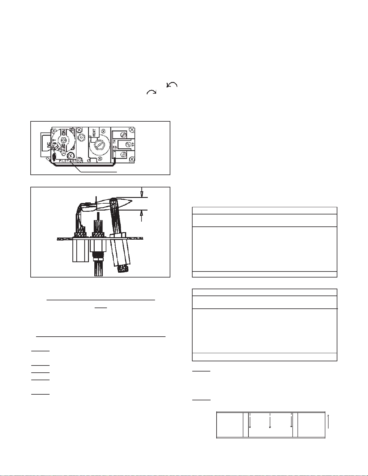
11. Turn gas control knob counterclockwise
to “ON”.
12. Turn temperature control knob to desired setting.
MODELS: VC201B-D, VC202B-D, VC351B-D, VC352B-D, VC501B-D, VC502B-D, VC701B-D,
VC702B-D, VCR351B-D, VCR352B-D, VCR501B-D, VCR502B-D, VCR701B-D, VCR702B-D
FOR YOUR SAFETY READ BEFORE LIGHTING
WARNING: Ifyou do not follow these instructions exactly,afireorexplosion may result
causingpropertydamage,personalinjury or loss oflife.
A. This appliancehasapilotwhichmust be lighted by hand.
When lighting the pilot, follow these instructions ex-
actly.
B. BEFORELIGHTINGsmellallaroundtheappliancearea
for gas. Be sure to smell next to the floor because some
gas is heavier than air and will settle on the floor.
WHATTODOIFYOUSMELLGAS:
•Do not try to light any appliance.
•Do not touch any electric switch; do not use any phone
in your building.
•Immediately call your gas supplier from a neighbor’s
phone. Follow the gas supplier’s instructions.
•Ifyoucannot reachyourgas supplier,call thefiredepartment.
C. Use only your hand to push in or turn the gas control knob.
Never use tools. If the knob will not push in or turn by
hand,don’ttryto repair it, callaqualifiedservicetechnician.
Force or attempted repair may result in a fire or explosion.
D. Do not use this appliance if any part has been under water.
Immediately call a qualified service technician to inspect
the appliance and to replace any part of the control system
and any gas control which has been under water.
LIGHTING INSTRUCTIONS
1. STOP! Read the information on the safety label.
2. Turn temperature control knob to “OFF” or it’s
lowest position.
3. Depress and turn gas control knob clockwise
to “OFF” position.
4. Wait five (5) minutes to clear out any gas. Then
smell for gas, including near the floor. If you smell
gas, STOP! Follow “B” in the information on the
safety label. If you don’t smell gas, go to the next
step.
5. Open casing door and pilot lighting hole cover.
6. Findpilot. (Follow metalpilottubefromgas control).
7. Locate red piezo ignitor button on top of heater.
8. Turn gas control knob counterclockwise to
“PILOT”.
9. Pushingas control knobandhold in. Immediately
begin a series of pushing and releasing the red
piezo ignitor button, while observing the pilot.
Continue to spark until pilot is lit. Continue to
hold the gas control knob in for about one (1)
minuteafterthepilot is lit. Releasethegascontrol
knob and it will pop back up. Pilot should remain
lit. If pilot goes out, repeat steps 3 thru 9.
• If knob does not pop up when released, STOP
andimmediatelycallyourservice technician
or gas supplier.
•If the pilot will not stay lit after several tries,
turn the gas control knob to “OFF” and call
your service technician or gas supplier.
TO TURN OFF GAS TO APPLIANCE
1. Turn the temperature control knob to it’s lowest setting.
2. Push in gas control knob slightly and turn clockwise to “OFF”. Do not force.
Page 10
Pilot is located on
end of combustion
chamber above
burner.
Gas Control Knob
NOTE: Knob can
not be turned from
“PILOT”to“OFF”
unless knob is
pushed in slightly.
Do not force.

Flametoo large 1. Defective operator section of gas valve. 1. Replace complete valve.
2. Burner orificetoo large. 2. See orifice chart to determine the correct orifice size
for your Model Number and elevation.
3. Pressure regulator malfunction. 3. Regulator must be adjusted by a qualified serviceman
using proper tools and instruments.
Noisy Flame 1. Noisy pilot. 1. Reduce pilot gas with adjusting screw on combination
gas. (Fig. 1).
2. Burr in orifice (if it whistles or resonates). 2. Remove burr or replace orifice (Do not enlarge orifice).
3. Excessive gas input. 3. See “FlameToo Large”,above.
Yellow tip flames (Some 1. Clogged main burner ports. 1. Clean main burner ports (Do not enlarge ports).
yellow tipping on LP Gas 2. Clogged draft hood. 2. Clean draft hood.
is permissible) 3. Linted up air shutter. 3. Check for dust or lint at air mixer opening and around
the shutter.
Floating Flame 1. Blocked venting. 1. Clean flue passageways to relieve blockage.
Gas Odor 1. Chimney or flue obstruction. 1. Clean flue.
2. Drafts around heater. 2. Eliminate drafts.
3. Gas leak. 3. Shut off gas service immediately. Check piping. Call
gas company. See “For Your Safety” (Page 1), and
“Gas Supply” (Page 3).
Delayed Ignition 1. Pilot flame too small. 1. Check pilot orifice, clean, increase pilot gas flow if
necessary by adjusting at combination control valve
(Fig. 1).
2. Burner ports clogged near pilot. 2. Clean burner ports (do not enlarge ports).
3. Low gas pressure. 3. Check gas supply pressure. See “Gas Supply”.
4. Pilot decreases in size when main 4. Supply piping is inadequately sized. Consult local gas
burners come on. utility or competent installer.
5. Drafts around unit. 5. Eliminate drafts.
6. Pilot lighter door open causing 6. Close pilot lighter door.
disturbance of pilot flame.
7. Improper venting. 7. See “Venting” (Page 2).
8. Pressure regulator malfunction. 8. Regulator must be adjusted by a qualified serviceman
using proper tools and instruments.
Failure to ignite 1. Main gas off. 1. Open all manual gas valves.
2. Defective gas valve. 2. Replace gas valve.
Condensation of 1. Improper venting. 1. See “Venting”.
water vapor.
Burner won’t turn off 1. Defective or sticking automatic valve. 1. Clean or replace valve.
2. Excessive gas pressure (The supply gas 2. To correct this situation contact the gas company
pressure must not exceed 1/2 psi or 14” supplying the gas. See “Gas Supply”.
water column).
Incorrect gas input 1. Gas input not checked. 1. Re-check gas input. See “Gas Supply”.
2. Cloggedorifice. 2. Check orifices for clogging. If clogged, clean out the
hole carefully with a smooth wood toothpick. (Do not
in any way enlarge or distort it).
3. Pressure regulator. 3. Regulator must be adjusted by a qualified serviceman
using proper tools and instruments.
4. Thermostat capillary tube damaged. 4. Replace bulb control switch.
SYMPTOM POSSIBLE CAUSES CORRECTIVE ACTION
TROUBLE SHOOTING CHART for qualified service technician - MAIN BURNER
TROUBLE SHOOTING CHART - POOR HEATING RESULTS
Page11

Not enough heat 1. Heater undersized. 1. This is especially true when a dwelling or room is
enlarged. Have the heat loss calculated and compare
to the heater output (70% of input). Your gas company
or installer can supply you with this information. If
heater is undersized, replace with correct size unit.
2. Temperature dial set too low. 2. Raise setting of temperature dial. See “Lighting and
Shutting Down Instructions”.
3. Incorrect gas supply pressure. 3. Check gas supply pressure and regulator pressure as
outlined above.
Too much heat 1. Temperature dial set too high. 1. Lower setting of temperature dial. See “Lighting and
Shutting Down Instructions”.
2. Combination control valve sticks open. 2. Replace combination control valve.
SYMPTOM POSSIBLE CAUSES CORRECTIVE ACTION
TROUBLE SHOOTING CHART - POOR HEATING RESULTS - Cont’d.
Burner won’t light 1. Pilot flame too large or too small. 1. Re-adjust pilot flame using adjustment on combination
control valves (See Fig. 1 & 1A).
2. Defective combination control valve. 2. Replace valve.
Pilot outage 1. Dirt in pilot orifice. 1. Clean pilot orifice with air or solvent, do not ream.
2. Pilot lighter door open. 2. Close pilot lighter door.
3. Defective automatic pilot section in 3. Replace combination control valve.
combination control valve.
4. Defective pilot generator. 4. Replace pilot generator.
5. Vent safety shut off system. 5. See “Venting” section.
Pilot will not stay lit 1. Pilot flame too large or too small. 1. Re-adjust pilot flame using adjustment on combination
when control knob control valves (See Fig. 1 & 1A).
is released 2. Defective pilot generator. 2. Replace pilot generator.
3. Defective gas valve. 3. Replace gas valve.
4. Loose connections at spill switch or 4. Tighten connections.
ECO on gas valve.
TROUBLE SHOOTING CHART - AUTOMATIC PILOT & VALVE
Page 12

Page 13
CHB-3 BLOWER INSTALLATION - (OPTIONAL)
(STANDARD ON 70,000 BTU UNITS ONLY)
Thiskitmustbeinstalledbyaqualifiedinstallerorservicetechnician.
STEP1. Run black wire and white wire that comes from bottom of junction box down through the heat shield. See FigureA.
STEP2. Insert junction box into opening in back of heater. Attach using four #8x1/2” black screws provided. See FigureA.
STEP3. Attach fan switch to fan switch bracket using two #8x1/2” plated, Phillip head screws provided. The 2” flange on the
bottom of bracket and terminals on the fan switch should be toward the back of the heater when properly installed.
STEP4. Locate the two engagement holes in base of heater. On a 35,000 Btu heater these holes are approximately 6-1/2” from the
backedgeandrightandleft holes are 5-1/4” and 7-1/4”respectfullyfromtheright side (as viewed from backofheater). On
a 50,000 Btu heater the holes are approximately 10-3/4” from the back edge and right and left holes are 5-3/8” and 7-3/8”
respectfully from the right side. Attach fan switch bracket to base using two #8x1/2” hex head screws provided. This will
require a ¼” socket and ratchet. See FigureA.
STEP5. Locate the blower opening and mounting tab on the base of the heater. Insert the front flange of the blower housing under
the mounting tab, lower the back of the blower down onto the base aligning the clearance holes in the blower base with the
engagement holes in the heater base. Secure the blower to the base with two #8 screws provided. See figureA.
STEP6. Connect black wire from junction box to right fan switch terminal. See Figure B.
STEP7. Connect white wire from junction box to white fan motor wire. See Figure B.
STEP8. Connect black wire from fan motor to left fan switch terminal. See Figure B.
STEP9. Turn variable speed control switch clockwise (as viewed from front of unit) to “OFF”.
STEP10. Plug power cord into 115V. grounded receptacle.
STEP11. Turnvariable speed control switchcounterclockwise (asviewedfromfront of unit) from “OFF”to“HIGH”. Blower
will now cycle on automatically when the switch temperature is met after the main burner comes on. The blower will
continue to run for a short period after the main burner goes off. Blower speed can be adjusted by setting the variable
speed control switch between high and low.
WARNING: This appliance is equipped with a three-prong (grounding) plug for your protection against shock hazard and must be
plugged directly into a properly grounded three-prong receptacle. Do not cut or remove the grounding prong from this
plug.
CAUTION: Label all wires prior to disconnection when servicing controls. Wiring errors can cause improper and dangerous
operation. Verify proper operation after servicing.
Heat Shield
Junction
Box
Speed
Control
Power
Cord
Fan Switch
Bracket
Blower
Housing
Mounting Tab
FIGUREA
BLACK
BLACK
WHITE
GREEN
MOTOR SPEED
CONTROL
WHITE
BLACK
FAN
SWITCH
MOTOR
“Ifany partof theoriginalwireassuppied
withthe appliancemust bereplaced, it
mustbereplaced withawire ofatleast
a105degree Ctemperaturerating.”
FIGUREB

TSK WALLSTAT KIT OPTIONAL
(VC/VCR-B“D”SERIES HEATERS)
WALLTHERMOSTATINSTALLATIONINSTRUCTIONS
Thiskitmustbeinstalledbyaqualifiedinstallerorservicetechnician.
Yourheatercanbe re-wiredto operatewithamillivoltwall thermostatby yourqualifiedinstaller/serviceperson.
Seewiringdiagrambelowforcorrectwiring.
NOTE: Donot disconnectthe wirefromtheblockedflueswitchto the“TH” terminalon thegas valve.
STEP1. Turntemperaturecontrol knobto“OFF” orlowest setting.
STEP2. Turngasvalve controlknobto “OFF”.
STEP3. Disconnect wireleadingfromPart#80180(BulbControlSwitch)fromvalve.
STEP4. Cut theremaining wireleadingfromPart#80180(BulbControl Switch)to theblocked flue
switch,leavingitsendconnectedtothe blockedflueswitchandleavingenoughlength toreach
thegas valve. Strip1/2”oftheinsulation fromthe cutendofthewire.
STEP5. Connect oneleg ofthermostatwiretothe“TH/PP” terminalonthegasvalve.
STEP6. Connect secondleg fromthethermostattothestrippedwire comingfrom theblocked flue
switch. Securethis connectioninside theheater cabinet.
STEP7. Secure bothredwires fromblockedflue switchinsideheater cabinet. Makesurenone ofthe
wireshave enoughslackto layagainst theheat exchangerordraft hood.
STEP8. Remove lightinginstructionsP/N 91237,91238,91239 fromback ofheaterand replacewith
P/N91242, 91243,91244lighting instructionssupplied inTSKKit.
STEP9. Follow lightinginstructionstoplaceheaterinoperation.
Page 14
REV. DATE: APRIL2011
BLOCKED
FLUESWITCH
THERMOSTAT
(OPTIONAL)
WIRE
NUT
(Notprovided)
PILOT
GENERATOR

MODELSINCLUDED:
VC-B“D”/ ClosedFrontCirculators
VCR-B“D” /Radiant FrontCirculators
CHB3Blower
VENTEDCONSOLEHEATER
Prices and specifications subject to
change without notice. All prices
areF.O.B.factory.
Page 15
REV. 06/13
ATTN: Contractors and Qualified
Service Technicians, we only sell
parts through our wholesalers, but the
prices listed are for your convenience.
For prompt parts service, contact the
wholesaler from which you purchased
your Cozy heater. NOTE: Parts &
schematic drawings on current models
are shown at www.cozyheaters.com.
NOTICE: When ordering any
component in the control train
assembly, specify either
Dexen,Honeywell,or
Robertshawcomponents.
43
51
47
44
46
50
45
49
42
48
21
33 25
29d
35
36
29b
29a
29c
29e 28a
28c
32a
16 1715
38 23
26
34
12
13
30
32
31
37
1
41
3
20
22
5
410 2
24
28
19
9
11
39
32a
18


LIMITED WARRANTY
Cozy Heating Systems LLC warrants to the
original user the accompanying product for the period
specified herein, provided said product is installed,
operated, maintained, serviced, and used according to
the instructions and specifications accompanying the
p
roduct. AS OUTLINED IN OUR
INSTRUCTIONS, ANY WARRANTY
CONSIDERATIONS ARE CONTINGENT ON
INSTALLATION BY A QUALIFIED INSTALLER
(CONTRACTOR). SELF-INSTALLATION IS
PROHIBITED AND WILL INVALIDATE YOUR
WARRANTY.
If within a period of one year from the date of
installation of the product, any part supplied by the
manufacturer proves to be defective due to
workmanship or material, it will replace such part,
p
rovided parts have not been subjected to misuse,
alteration, neglect, or accidents. The term of the
warranty for the heat exchanger and burners is covered
in Table A below. Any claim not made within ten (10)
days after the expiration of the warranty period shall be
deemed waivedby the user.
The manufacturer shall have no liability or be
required to perform any obligation under this warranty
unless, when requested, the user returns, at the user’s
expense, the component or product claimed defective,
to the manufacturer for inspection, to enable the
manufacturer to determine if the claimed defect is
covered by this warranty.
No charges for freight, labor or other
expenses incurred in the repair, removal, or
replacement of anyproduct or component claimed to be
defective, will be paid by the manufacturer to the user,
and the manufacturer will not be liable for any
expenses incurred, bythe user, in remedyingany defect
inthe product.
Service under this warranty is the
responsibility of the installer. In the event service
under this warranty is needed, the user of the produc
t
shall request such service directly from the installer. I
f
the user is unable to locate the installer, the use
r
should write directly to the manufacturer, and the
name ofan alternative service sourcewillbe supplied.
The product safety registration card (packe
d
inside the appliance)must be completed and returnedt
o
the factory.
THIS WARRANTY IS EXPRESSLY I
N
LIEU OF ANY OTHER WARRANTIES, EXPRESS
OR IMPLIED (WHETHER WRITTEN OR ORAL).
ANY IMPLIED WARRANTY OF
MERCHANTABILITY OR OF FITNESS FOR
A
PARTICULAR PURPOSE IS EXPRESSLY LIMITED
TO THE DURATION OF THE MANUFACTURER’S
EXPRESS, WRITTEN WARRANTY.
UNDER NO CIRCUMSTANCES SHALL
THE MANUFACTURER BE LIABLE FOR AN
Y
SPECIAL, INDIRECT OR CONSEQUENTIAL
DAMAGES OR EXPENSES ARISING DIRECTL
Y
OR INDIRECTLY FROM ANY COMPONENT O
R
FROM THE USE THEREOF. THE REMEDIES SET
FORTH HEREIN SHALL BE THE EXCLUSIVE
REMEDIES AVAILABLE TO THE USER AND ARE
IN LIEUOF ALL OTHER REMEDIES.
SOME STATES DO NOT ALLO
W
LIMITATIONS ON HOW LONG AN IMPLIED
WARRANTY LASTS, SO THE ABOVE
LIMITATIONS MAY NOT APPLY TO YOU.
SOME STATES DO NOT ALLOW THE
EXCLUSION OR LIMITATION OF INCIDENTAL
OR CONSEQUENTIAL DAMAGES, SO THE
ABOVE LIMITATIONS OR EXCLUSIONS MA
Y
NOT APPLY TO YOU.
THIS WARRANTY GIVES YOU SPECIFI
C
LEGAL RIGHTS, AND YOU MAY ALSO HAVE
OTHER RIGHTS, WHICH VARY, FROM STATE
TO STATE.
COZY HEATING SYSTEMS LLC
3230 INDUSTRIAL PARKWAY. – JEFFERSONVILLE, IN 47130
TABLE A
Warranty Period
Product Heat Exchanger/Tubes Burners
Cozy Gas Fired Floor Furnace 10 Years 10 Years
Cozy Gas Fired Wall Furnace 10 Years 10 Years
Cozy Gas Fired Vented Console Heater 10 Years 10 Years
Cozy Gas Fired Direct Vent Heater 10 Years 10 Years
Cozy Gas Fired Counterflow Furnace 10 Years 10 Years
Cozy Gas Fired Counterflow Direct Vent Furnace 10 Years 10 Years
Cozy Gas Fired Mobile HomeDirectVentFurnace 10 Years 10Years
Cozy Gas Fired Hi-Efficient Direct Vent Wall Furnace 10 Years 10 Years
Cozy Gas Fired Direct Vent Baseboard Heater 10 Years 10 Years
Cozy Fan-Type, Direct Vent Through-The-Wall Gas Heater 10 Years 10 Years
Cozy Blue Flame Vent Free Heater N/A 10 Years
Cozy Infra-Red Vent Free Heater N/A N/A
This manual suits for next models
13
Table of contents
Other COZY Heater manuals
Popular Heater manuals by other brands

Jaga
Jaga heatwave Mounting instructions

UNIPRODO
UNIPRODO UNI_SAUNA_B4.5KW user manual

HeatStar
HeatStar ER2STG 80-125 Operating instructions and owner's manual

Systema
Systema INFRA...ROSSO SCR 1 25M instruction manual

Master
Master REM 2 EPB User and Maintenance Book

Blaupunkt
Blaupunkt EH5010 owner's manual