Harwil L-21 User manual

ULTRA RELIABLE SINCE 1956 P. 1
MODEL L-21 HARWIL CORPORATION
541 KINETIC DRIVE, OXNARD, CA 93030
TEL: (805) 988-6800 FAX: (805) 988-6804
EMAIL: HARWIL@HARWIL.COM
UP
UP
FLOAT DOWNFLOAT UP
CABLE GROMMET 'A'
CABLE GROMMET 'AA'
CABLE GROMMET 'B'
CABLE GROMMET 'C'
STRAIN RELIEF NUT
INTERNAL 15A MICROSWITCH
1¼” NPT THREAD
COVER, INCLUDING O-RING
SEAL, RETAINING SCREWS
THREADED BODY COMPLETE,
INCLUDING SWITCH BRACKET
FLOAT SHAFT
OR
FLOAT SHAFT
EXTENDED LENGTH
FLOAT
MAGNET HOUSING
10652-12-1 1.0” DIFF.
10652-12-2 2.0” DIFF.
10652-12-3 3.0” DIFF.
10652-12-5 5.0” DIFF.
PIVOT SUPPORT
‘F’ COVER
½” INTERNAL THREADS FIT
STANDARD ½” ELECTRICAL
AND PLUMBING FITTINGS
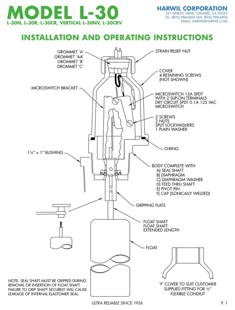
INSTALLATION AND OPERATING INSTRUCTIONS

ULTRA RELIABLE SINCE 1956P. 2
MODEL L-21 HARWIL CORPORATION
541 KINETIC DRIVE, OXNARD, CA 93030
TEL: (805) 988-6800 FAX: (805) 988-6804
EMAIL: HARWIL@HARWIL.COM
INSTALLATION AND OPERATING INSTRUCTIONS
FLOAT UP/DOWN CONFIGURATION
1. If the shipping container and contents are re-
ceived damaged, immediately call the shipping
company for damage inspection and file the ap-
propriate report, sending a copy to Harwil Corp.
for product replacement and insurance adjust-
ment.
2. If the contents are not damaged, inspect the units
received against the packing list and the original
purchase order. If incorrect units are received,
call Harwil Corp. immediately for resolution of
the problem.
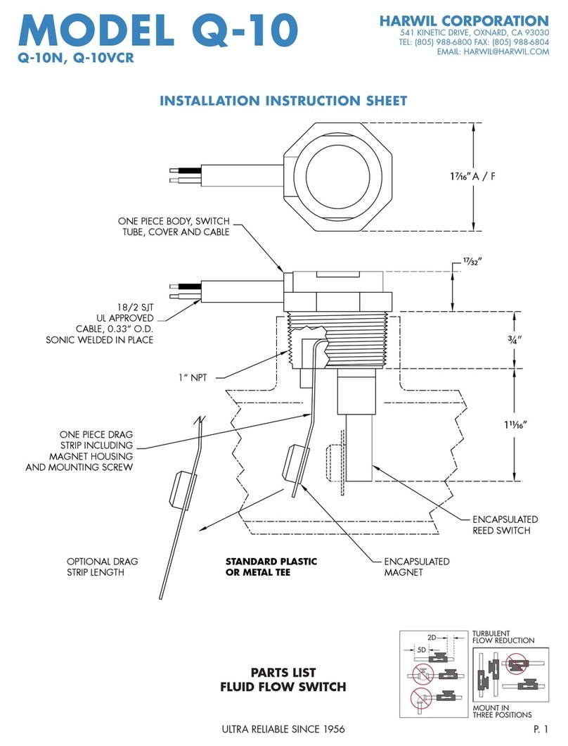
3. Check for damage or scuffing on the Teflon
tape applied to the 1¼” NPT threads of the
switch body. Re-tape as required with 2 to 3 lay-
ers wound clockwise (looking at the end of the
threaded body with the float toward the viewer).
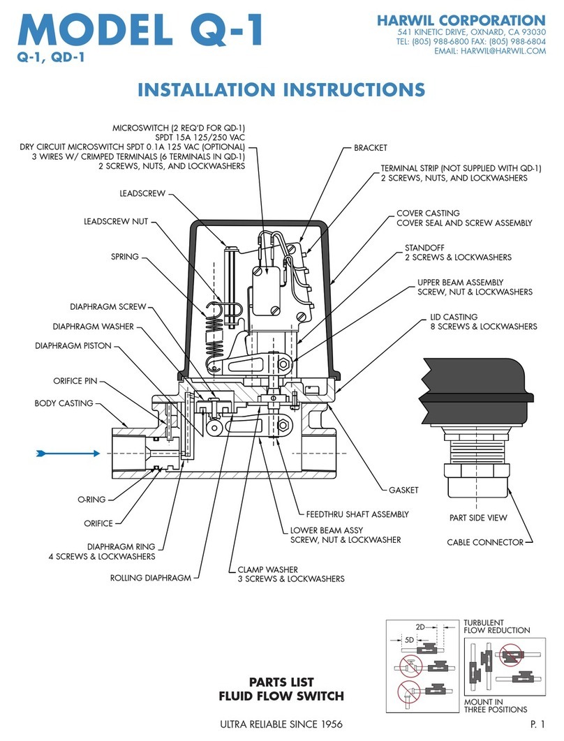
4. Remove the cover and check switch action with a
multimeter while moving the float up and down.
ACTUATION ARM
NORMALLY CLOSED (NC)
NORMALLY OPEN (NO)
COMMON
UP
FLOAT
POSITION
MULTIMETER
CONNECTION METER READING
UP
COMM. AND NO
TERMINALS CONTINUITY
COMM. AND NC
TERMINALS OPEN CIRCUIT
DOWN
COMM. AND NO
TERMINALS OPEN CIRCUIT
COMM. AND NC
TERMINALS CONTINUITY
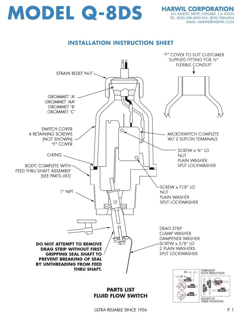
5. Replace the domed cover on the unit and insert the float through the 1¼” NPT hole in the tank.
Mate the switch body threads with tank threads and tighten with an appropriate wrench until the
thread joint is leak-tight and the arrow on the cover label is pointing vertically upward.
NOTE: Model L-21 can be supplied with 1½” x 1¼” or larger reducer bushings as required to fit existing
large holes in a tank wall.
6. Remove the cover and wire as indicated on page 3.

ULTRA RELIABLE SINCE 1956 P. 3
MODEL L-21 HARWIL CORPORATION
541 KINETIC DRIVE, OXNARD, CA 93030
TEL: (805) 988-6800 FAX: (805) 988-6804
EMAIL: HARWIL@HARWIL.COM
LOW LIQUID LEVEL ALARM
Fig 1: Wiring schematic for power applied to load when
liquid level is less than set point (power to load interrupted
when level increases to above set point).
Decreasing liquid level moves actuator in direction shown.
HIGH LIQUID LEVEL ALARM
Fig 2: Wiring schematic for power applied to load when
liquid level is greater than set point (power to load inter-
rupted when level decreases to below set point).
Increasing liquid level moves actuator in direction shown.
MICROSWITCH
NC
NO
(HOT)
LOAD
LINE
COM
MICROSWITCH
NC
NO
(HOT)
LOAD
LINE
COM
Microswitch actuation point may be monitored by an audible click or with an ohmmeter before connecting line power to the
switch terminals or by monitoring the voltage supplied to the load through the microswitch.
* Pump Up wiring diagram same as low level alarm shown in Fig. 1
* Pump Down wiring diagram same as high level alarm shown in Fig. 2
* Electrical Wiring (Strain Relief Grommet):
Step 1) Remove the gland nut, grommet, and switch cover.
Step 2) Strip the outer jacket of the electrical cord back
approximately 1¼” (inches). Strip insulation from
individual conductors back approximately ¼”
(inch).
Step 3) Slip-on terminals are supplied with each switch.
Remove from switch terminals and crimp on or solder to electrical leads.
Step 4) Feed the electrical cable through the strain relief nut, grommet, and switch cover.
Step 5) Apply slip-on terminals to appropriate contacts of microswitch. Slide cover down the cable and fasten it to the body
of the switch with four (4) screws provided. Slide grommet down the cable and push the grommet into the tapered
end of the cover. Hold the cable jacket to prevent rotation and thread gland nut firmly onto cover.
¼”
1¼”
* Electrical Wiring (‘F’ Cover):
Step 1) Remove switch cover.
Step 2) Strip the outer jacket of the electrical cord back
approximately 1¼” (inches). Strip insulation from in-
dividual conductors back approximately ¼” (inch).
Step 3) Slip-on terminals are supplied with each switch. Re-
move from switch terminals and crimp on or solder
to electrical leads.
Step 4) Thread user supplied ½” flexible conduit fitting into
½” female thread on end of cover. Feed electrical
cable through conduit fitting.
Step 5) Apply slip-on terminals to appropriate male spade
contacts on microswitch. Slide cover down cable
and fasten to body of switch with four (4) screws
provided. Be sure to install the “O” ring between
the body and cover. Connect flexible ½” metal or
plastic conduit-to-conduit fitting on end of cover per
standard procedure.

ULTRA RELIABLE SINCE 1956P. 4
MODEL L-21 HARWIL CORPORATION
541 KINETIC DRIVE, OXNARD, CA 93030
TEL: (805) 988-6800 FAX: (805) 988-6804
EMAIL: HARWIL@HARWIL.COM
1, 2, 3, AND 5 INCH
LINE REPLACEABLE
DIFFERENTIAL FLOAT
UNITS AVAILABLE AS
SEPARATE ITEMS.

ULTRA RELIABLE SINCE 1956 P. 5
MODEL L-21 HARWIL CORPORATION
541 KINETIC DRIVE, OXNARD, CA 93030
TEL: (805) 988-6800 FAX: (805) 988-6804
EMAIL: HARWIL@HARWIL.COM
14
8
10
11
9
7
13
19
16
15
617 18
4
5
1
2
3
12
L-21N (Series 21300)
# PART NAME QTY PART #
1 STRAIN RELIEF NUT (1) 60127
2 GROMMET
#A BUNA N (OPTIONAL) (1) 10440
#AA BUNA N (OPTIONAL) (1) 10441
#B BUNA N (OPTIONAL) (1) 10442
#C BUNA N (OPTIONAL) (1) 10443
3 COVER (MALE) NORYL (OPTIONAL) (1) 60125
4 COVER (FEMALE) NORYL (OPTIONAL) (1) 60126
5 SCREW (4) 109-S
6 MICROSWITCH (ASSEMBLY ONLY) (1) 21301
STEEL PLATE (1) 21302
CERAMIC MAGNET (3) 21303
EPOXY 21350
7 BODY - NORYL (INCL SWITCH BRACKET) (1) 21304
8 PIVOT SUPPORT (1) 21305
# PART NAME QTY PART #
9 MAGNET HOUSING (ASSEMBLY ONLY) (1) 21306
1.0” CERAMIC MAGNET (OPT) (1) 21307
2.0” CERAMIC MAGNET (OPT) (1) 21308
3.0” CERAMIC MAGNET (OPT) (1) 21309
5.0” CERAMIC MAGNET (OPT) (1) 21310
10 SHAFT - 316 STAINLESS STEEL (1) 21311
11 FLOAT - NORYL (1) 65601
12 FLOAT - POLYPROPYLENE (OPT) (1) 65602
13 O-RING (1) 65110
14 SCREW (2) 147-S
15 TERMINALS (3) 706-T
16 SCREW (2) 101-S
17 SCREW (1) 116-S
18 SCREW (1) 104-S
19 NUT (1) 202-N

ULTRA RELIABLE SINCE 1956P. 6
MODEL L-21 HARWIL CORPORATION
541 KINETIC DRIVE, OXNARD, CA 93030
TEL: (805) 988-6800 FAX: (805) 988-6804
EMAIL: HARWIL@HARWIL.COM
14
8
10
11
9
7
13
19
16
15
617 18
4
5
1
2
3
12
L-21R (Series 21400)
# PART NAME QTY PART #
1 STRAIN RELIEF NUT - FORTRON (1) 65301
2 GROMMET
#A BUNA N (OPTIONAL) (1) 10440
#AA BUNA N (OPTIONAL) (1) 10441
#B BUNA N (OPTIONAL) (1) 10442
#C BUNA N (OPTIONAL) (1) 10443
3 COVER (MALE) FORTRON (OPTIONAL) (1) 65302
4 COVER (FEMALE) FORTRON (OPTIONAL) (1) 65303
5 SCREW (4) 109-S
6 MICROSWITCH (ASSEMBLY ONLY) (1) 21301
STEEL PLATE (1) 21302
CERAMIC MAGNET (3) 21303
EPOXY 21350
7 BODY - FORTRON (INCL SWITCH BRACKET) (1) 21401
8 PIVOT SUPPORT (1) 21402
# PART NAME QTY PART #
9 MAGNET HOUSING (ASSEMBLY ONLY) (1) 21403
1.0” CERAMIC MAGNET (OPT) (1) 21307
2.0” CERAMIC MAGNET (OPT) (1) 21308
3.0” CERAMIC MAGNET (OPT) (1) 21309
5.0” CERAMIC MAGNET (OPT) (1) 21310
10 SHAFT - 316 STAINLESS STEEL (1) 21311
11 FLOAT - FORTRON (1) 65805
12 FLOAT - POLYPROPYLENE (OPT) (1) 65602
13 O-RING (1) 65110
14 SCREW (2) 147-S
15 TERMINALS (3) 706-T
16 SCREW (2) 101-S
17 SCREW (1) 116-S
18 SCREW (1) 104-S
19 NUT (1) 202-N

ULTRA RELIABLE SINCE 1956 P. 7
MODEL L-21 HARWIL CORPORATION
541 KINETIC DRIVE, OXNARD, CA 93030
TEL: (805) 988-6800 FAX: (805) 988-6804
EMAIL: HARWIL@HARWIL.COM
14
8
10
11
9
7
13
19
16
15
617 18
4
5
1
2
3
12
L-21VCR (Series 21500)
# PART NAME QTY PART #
1 STRAIN RELIEF NUT - FORTRON (1) 65301
2 GROMMET
#A VITON (OPTIONAL) (1) 65701
#B VITON (OPTIONAL) (1) 65703
#C VITON (OPTIONAL) (1) 65704
3 COVER (MALE) FORTRON (OPTIONAL) (1) 65302
4 COVER (FEMALE) FORTRON (OPTIONAL) (1) 65303
5 SCREW (4) 109-S
6 MICROSWITCH (ASSEMBLY ONLY) (1) 21302
STEEL PLATE (1) 21302
CERAMIC MAGNET (3) 21303
EPOXY 21350
7 BODY - FORTRON (INCL SWITCH BRACKET) (1) 21407
8 PIVOT SUPPORT (1) 21402
# PART NAME QTY PART #
9 MAGNET HOUSING (ASSEMBLY ONLY) (1) 21403
1.0” CERAMIC MAGNET (OPT) (1) 21307
2.0” CERAMIC MAGNET (OPT) (1) 21308
3.0” CERAMIC MAGNET (OPT) (1) 21309
5.0” CERAMIC MAGNET (OPT) (1) 21310
10 SHAFT - HASTELLOY C (1) 21501
11 FLOAT - FORTRON (1) 65805
12 FLOAT - POLYPROPYLENE (OPT) (1) 65602
13 O-RING (1) 65110
14 SCREW (2) 145-S
15 TERMINALS (3) 706-T
16 SCREW (2) 101-S
17 SCREW (1) 116-S
18 SCREW (1) 104-S
19 NUT (1) 219-N

ULTRA RELIABLE SINCE 1956P. 8
CERTIFICATE OF CONFORMANCE
All HARWIL Corporation (“HARWIL”) products are manufactured using new materials and components.
Our products meet the applicable performance and materials specifications indicated in our current
Specifications Sheets and Parts Lists. HARWIL endeavors to obtain its materials and components from
American Companies.
DOMINANCE OF HARWIL LIMITED EXPRESS WARRANTY
HARWIL warrants that all HARWIL products will be free from defects in material and workmanship for a
period of one year from the date of original shipment. This warranty shall be limited to the replacement
and reconditioning of our products and parts. HARWIL reserves the right and sole discretion to modify or
change the composition, design and appearance of its products at anytime.
This warranty shall be in lieu of all warranties of merchantability and of all warranties of fitness for a par-
ticular purpose relating to harwil products and parts. Buyer’s sole remedy hereunto shall be replacement
or reconditioning as set forth herein.
HARWIL shall incur no obligations hereunder and no liability in the event of (a) buyer not fulfilling its re-
sponsibilities, including as set forth herein; (b) neglect, alteration or improper product use, including use
with non-compatible devices or chemicals; or (c) repair by other than HARWIL. ANY LAWSUIT RELATING
TO THIS WARRANTY MUST BE COMMENCED WITHIN ONE YEAR OF THE DATE IT ACCRUES.
Each user of our product should make appropriate analysis and tests to determine the suitability of the
product for the intended use prior to purchase. HARWIL provides no warranty and assumes no respon-
sibility for corrosive attack on any material, component or design features associated with any of its
products.
Corrosion resistance information listed in HARWIL specification sheets, installation sheets and product
brochures is solely for general background information. This table has been compiled from literature
published by various material suppliers and by equipment manufacturers who use these materials in
their products. Inasmuch as these data are based on tests by entities over which HARWIL has no control,
HARWIL does not guarantee or accept responsibility for the accuracy of such tests. When using the table,
please remember that in any given case several factors such as concentration, temperature, degrees of
agitation and presence of impurities influence the rate of corrosion. The guide is intended, in a general
way, to rate materials for resistance to chemicals which contain their usual impurities and for types of
equipment in common use. Ratings should be used only as a general guide to first approximation of your
material requirements rather than as the final answer.
• When in doubt, test materials before installation.
• After installation, follow up with preventative maintenance and periodic inspection.
Table of contents
Other Harwil Switch manuals
Popular Switch manuals by other brands
Dell
Dell Powerconnect W-ClearPass Hardware Appliances Hardware installation guide
Brocade Communications Systems
Brocade Communications Systems A7533A - Brocade 4Gb SAN Switch Base Troubleshooting

Digitus
Digitus DS-15202-1 Quick installation guide

Manhattan
Manhattan 161527 instructions

ZyXEL Communications
ZyXEL Communications ES1100 Series user guide
H3C
H3C S5120-EI Series Configuration guide

Belkin
Belkin OmniView F1DS102J Specifications
SMART
SMART SMART PE260 Configuration guide
Delta Electronics
Delta Electronics Agema Series installation guide

TRENDnet
TRENDnet TI-PG541i user guide
Tork
Tork W100 Installation and operating instructions
Rohde & Schwarz
Rohde & Schwarz R&S OSP-B157W8 PLUS Getting started
