Harwil Q-5 Service manual

ULTRA RELIABLE SINCE 1956 P. 1
MODEL Q-5 HARWIL CORPORATION
541 KINETIC DRIVE, OXNARD, CA 93030
TEL: (805) 988-6800 FAX: (805) 988-6804
EMAIL: HARWIL@HARWIL.COM
Q-5, Q-5SS, QD-5, QD-5SS
PARTS LIST
FLUID FLOW SWITCH
TERMINAL STRIP
(NOT SUPPLIED WITH QD-5)
BRACKET
2 SPACERS
2 SCREWS & LOCKWASHERS
LEADSCREW
LEADSCREW NUT
SPRING
LARGE SPRING
LID CASTING
7 SCREWS & LOCKWASHERS
CLAMP WASHER
3 SCREWS & LOCKWASHERS
SPDT 15A MICROSWITCH 125/240 VAC (2 REQ'D FOR QD-5)
DRY CIRCUIT MICROSWITCH SPDT 0.1A 125 VAC (OPTIONAL)
3 WIRES W/ CRIMPED TERMINALS (6 TERMS. ONLY QD-5)
2 SCREWS, NUTS & LOCKWASHERS
COVER CASTING,
SEAL, SCREW ASSEMBLY
CABLE STRAIN RELIEF
GASKET
BODY CASTING
FEED THRU SHAFT ASSEMBLY
MODEL Q5/3
MODEL Q5/5
MODEL Q5/7
DRAG DISK 1
DRAG DISK 2
DRAG DISK 3
DRAG DISK 4
DRAG DISK 5
DRAG DISK 6
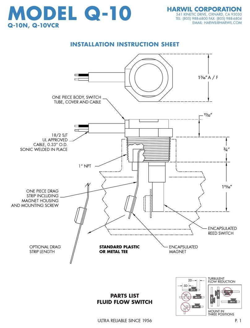
This parts list applies to all models of Q-5 and QD-5 fluid flow switches: Q-5/3, Q-5/7, QD-5/7.
All letters and numbers added to model number after the above numbers apply to optional drag strips
and electrical strain relief connectors.
TURBULENT
FLOW REDUCTION
MOUNT IN
THREE POSITIONS
2D
5D
INSTALLATION INSTRUCTIONS

ULTRA RELIABLE SINCE 1956P. 2
MODEL Q-5 HARWIL CORPORATION
541 KINETIC DRIVE, OXNARD, CA 93030
TEL: (805) 988-6800 FAX: (805) 988-6804
EMAIL: HARWIL@HARWIL.COM
Q-5, Q-5SS, QD-5, QD-5SS
INSTALLATION AND OPERATING INSTRUCTIONS
The gasket seal located between the main body casting and the lid casting is a cork-rubber composi-
tion, which is subject to a slight creep for a short period after application of the initial clamping load.
All gaskets are properly clamped before shipment, however during shipping and storage, the gasket
may compress, allowing the body-lid clamp bolts to become slightly loose. Tighten these bolts before
assembling the flow switch in-system. No further creep of gasket will occur after second tightening. The
Q-5 fluid flow switch is supplied with a male 1” NPT which is threaded into an appropriate pipe tee,
large pipe with reducer bushing, or directly into a hole threaded 1” NPT in the wall of the pipe. Turn
until tight and arrow on body casting is pointed in direction of flow.
ELECTRICAL WIRING
FIGURE 1: Wiring schematic for power applied to load when flow is GREATER than the set point (pow-
er to load interrupted when flow is LESS than set point).
FIGURE 2: Wiring schematic for power applied to load when flow is LESS than the set point (power to
load interrupted when flow is GREATER than set point).
MICROSWITCH
TERMINAL STRIP
INCREASING FLOW MOVES
ACTUATOR IN DIRECTION SHOWN
COM (BLACK)
NC (ORANGE)
NO (WHITE)
(HOT)
LOAD
LINE
MICROSWITCH
TERMINAL STRIP
COM (BLACK)
NC (ORANGE)
NO (WHITE)
(HOT)
LOAD
LINE
DECREASING FLOW MOVES
ACTUATOR IN DIRECTION SHOWN

ULTRA RELIABLE SINCE 1956 P. 3
MODEL Q-5 HARWIL CORPORATION
541 KINETIC DRIVE, OXNARD, CA 93030
TEL: (805) 988-6800 FAX: (805) 988-6804
EMAIL: HARWIL@HARWIL.COM
Q-5, Q-5SS, QD-5, QD-5SS
Q-5 FLOW SWITCH OPERATIONAL ADJUSTMENT
SWITCH POINT ADJUSTMENT
1. Remove cover.
2. Adjust fluid flow in system to desired rate WITHOUT regard to Q-5 switch point setting.
3. The switch point adjusting mechanism consists of an adjusting screw, a “U” shaped lead screw nut,
and a helical spring.
CLOCKWISE rotation of the adjusting screw changes the microswitch actuation point toward HIGHER
flow rates.
NOTES: All Q-5 units are factory set at the lower end of the flow range, e.g. the adjusting screw is set
at the low flow counter-clockwise position.
The lead screw nut locks the adjusting screw in position, maintaining the flow switch set point under all
environmental conditions.
4. Turn the adjusting screw in a clockwise direction until the microswitch is actuated, while maintaining
the desired fluid flow rate in the system. Turn the adjusting screw TWO (2) additional turns in the
clockwise direction and then slowly back off in a counter-clockwise direction, until the microswitch
is again actuated. The Q-5 flow switch is now set for maximum sensitivity for detecting small flow
changes.
5. When set for maximum sensitivity (100% point) as described above, flow turbulence may cause
rapid on/off switching (dithering) of the microswitch contacts, resulting in reduced switch contact life
ADJUST LEADSCREW
BEST ADJUSTMENT POINT
(CENTERED)
MICROSWITCH
LEADSCREW
SPRING POSITION
WHEN DELIVERED
REMOVE COVER

ULTRA RELIABLE SINCE 1956P. 4
MODEL Q-5 HARWIL CORPORATION
541 KINETIC DRIVE, OXNARD, CA 93030
TEL: (805) 988-6800 FAX: (805) 988-6804
EMAIL: HARWIL@HARWIL.COM
Q-5, Q-5SS, QD-5, QD-5SS
and “noise” in the electrical circuit. This is eliminated by turning the adjusting screw in a counter-
clockwise direction.
6. Microswitch actuation point may be monitored during the adjustment procedure detailed in steps 4
and 5 by an audible click or with an ohmmeter before connecting line power to the terminal strip,
or by monitoring the voltage supplied to the load through the microswitch.
7. If the system flow rate is changed, the Q-5 can be adjusted to monitor the new flow rate by turning
the adjusting screw in a counter-clockwise direction to the minimum flow position and then proceed-
ing as in 4 and 5 above.
8. In the event that the system flow is at the desired rate and the adjustment mechanism runs out of
80%
50%
ADJUSTED MAX. SENSITIVITY
AS DESCRIBED IN 5.
REDUCED SET POINT TO
ELIMINATE DITHER AND
MAINTAIN SENSITIVITY
NORMAL SET POINT WHICH
ELIMINATES BOTH DITHERING AND
NUISANCE TRIPS WILE PROVIDING
SAFE FLOW SIGNAL OUTPUT.
LEADSCREW
BOTTOM OF LEADSCREW
50%
80%
100%
100%

ULTRA RELIABLE SINCE 1956 P. 5
MODEL Q-5 HARWIL CORPORATION
541 KINETIC DRIVE, OXNARD, CA 93030
TEL: (805) 988-6800 FAX: (805) 988-6804
EMAIL: HARWIL@HARWIL.COM
Q-5, Q-5SS, QD-5, QD-5SS
travel (e.g., the lead screw nut is at either end of the support bracket before the microswitch is actu-
ated), then the drag disk must be changed to shift the flow switch flow range so that it straddles the
system flow rate.
Example: If the Q-5 is fitted with a #2 drag disk and procedure 4 has been followed, the adjusting
lead screw has been turned clockwise until the lead screw nut is at the extreme end of the support
bracket and the microswitch has still not been actuated, then the flow is too low and different drag
disk must be substituted and procedure 4 repeated.
GENERAL RULES FOR SELECTING A NEW DRAG DISK
TILTED UPSTREAM
SPRING FULLY EXTENDED
DESIRED FLOW RATE DESIRED FLOW RATE
THEN REPLACE DRAG DISK
WITH NEXT SMALLER SIZE THEN REPLACE DRAG DISK
WITH NEXT LARGER SIZE
IF IF
TILTED DOWNSTREAM
SPRING NOT EXTENDED
Drag Disk Change
1. Remove the flow switch from the pipe line.
2. Remove the small screws attaching the drag disk target to the feed thru shaft.
3. Replace the old target with a new one and tighten the screws.
Terminal Strip Wiring
1. Loosen the round gland nut located on the electrical cable fitting.
2. Insert the cable through the grommet in the electrical cable fitting and tighten the gland nut sufficient-
ly to seal the cable in place.
3. Strip the conductor ends approximately 3/16”
4. Loosen the appropriate terminal strip screw and remove the empty terminal. Insert bare wire in
terminal barrel and crimp. Place terminal strip in SAME orientation as received. This is IMPORTANT,
since terminals and wires may interfere with the cover if the orientation is changed.

ULTRA RELIABLE SINCE 1956P. 6
MODEL Q-5 HARWIL CORPORATION
541 KINETIC DRIVE, OXNARD, CA 93030
TEL: (805) 988-6800 FAX: (805) 988-6804
EMAIL: HARWIL@HARWIL.COM
Q-5, Q-5SS, QD-5, QD-5SS
Q-5 (SERIES 20200)
# PART NAME QTY PART #
1 COVER CASTING (1) 20300
2 SCREW (1) 112-S
3 LOCK WASHER (1) 321-W
4 SCREW (7) 107-S
5 WASHER (7) 319-W
6 LID CASTING (1) 20301
7 CONNECTOR CABLE (OPTIONAL) (1) 60116
BODY (1) 10429
NUT (1) 10430
GROMMET #A (OPTIONAL) (1) 10440
GROMMET #AA (OPTIONAL) (1) 10441
GROMMET #B (OPTIONAL) (1) 10442
GROMMET #C (OPTIONAL) (1) 10443
LOCK NUT (1) 101-DC
O-RING (1) 20117
8 CONNECTOR CABLE (OPTIONAL) (1) 20115
9 CONNECTOR CABLE (OPTIONAL) (1) 20116
10 FEED THRU SHAFT (ASSEMBLY ONLY) (OPTIONAL) (1) 20201
11 FEED THRU SHAFT (ASSEMBLY ONLY) (OPTIONAL) (1) 20202
12 FEED THRU SHAFT (ASSEMBLY ONLY) (OPTIONAL) (1) 20203
RUBBER MOLDED (1) 20134
PIN (1) 20135
13 DRAG DISK #1 (OPTIONAL) (1) 20303
DRAG DISK #2 (OPTIONAL) (1) 20304
14 DRAG STRIP #3 (OPTIONAL) (1) 20204
DRAG STRIP #4 (OPTIONAL) (1) 20205
DRAG STRIP #5 (OPTIONAL) (1) 20206
DRAG STRIP #6 (OPTIONAL) (1) 20207
# PART NAME QTY PART #
15 SCREW (1) 152-S
16 WASHER (2) 311-W
17 CLAMP WASHER (1) 324-W
18 SCREW (3) 118-S
19 GASKET (1) 20307
20 BODY CASTING (1) 20208
21 SPACER (2) 20305
22 SPRING (Q-5/3 ONLY) (1) 20316
23 SPRING (Q-5/5 AND Q-5/7) (1) 20108
24 LEAD SCREW NUT (1) 20107
25 LEAD SCREW (1) 132-S
26 SHRINK WRAP (1) 901-F
27 NUT (2) 201-N
28 WASHER (1) 300-W
29 WASHER (2) 311-W
30 BRACKET (1) 20314
31 TERMINAL STRIP (1) 20102
32 WASHER (2) 313-W
33 SCREW (2) 117-S
34 MICROSWITCH (1) 20103
35 SCREW (2) 116-S
36 TERMINALS (3) 708-T
37 TERMINALS (3) 706-T
38 WIRE (1) 20318
39 WIRE (1) 20317
40 WIRE (1) 20319
41 LABEL (1) 20320
16
15
19
6
5
41
2
3
36
40
38
37
39
31
35
34
21
25
22
23
26
24
27
30
28
29
33
32
20
15
13
17
18
10
11
12
7
9
8

ULTRA RELIABLE SINCE 1956 P. 7ULTRA RELIABLE SINCE 1956
CERTIFICATE OF CONFORMANCE
All Harwil Corporation (“HARWIL”) products are manufactured using new materials and components.
Our products meet the applicable performance and materials specifications indicated in our current
Specifications Sheets and Parts List. HARWIL endeavors to obtain its materials and components from
American Companies.
DOMINANCE OF HARWIL LIMITED EXPRESS WARRANTY
Each user MUST make appropriate analysis and tests to determine the suitability of the HARWIL product
for the intended use prior to purchase.
HARWIL warrants that all HARWIL products will be free from defects in material and workmanship for a
period of one year from the date of original shipment. This Warranty shall be LIMITED to the replacement
and reconditioning of our products and parts. HARWIL reserves the right and sole discretion to modify
or change the composition, design and appearance of its products at anytime.
THIS WARRANTY SHALL BE IN LIEU OF ALL WARRANTIES OF MERCHANTABILITY AND OF ALL WAR-
RANTIES OF FITNESS FOR A PARTICULAR PURPOSE RELATING TO HARWIL PRODUCTS AND PARTS.
BUYER’S SOLE REMEDY SHALL BE REPLACEMENT OR RECONDITIONING AS SET FORTH HEREIN.
HARWIL SHALL INCUR NO OBLIGATIONS HEREUNDER AND NO LIABILITY IN THE EVENT OF (1)
BUYER NOT FULFILLING ITS RESPONSIBILITIES; INCLUDING AS SET FORTH HEREIN; (2) NEGLECT,
ALTERATION OR IMPROPER PRODUCT USE, INCLUDING USE WITH NON-COMPATIBLE DEVICES OR
CHEMICALS; OR (3) REPAIR BY ANOTHER COMPANY OR PERSON THAN HARWIL.
ANY LAWSUIT RELATING TO THIS LIMITED EXPRESS WARRANTY MUST BE COMMENCED WITHIN
ONE YEAR OF THE DATE THE LAWSUIT ACCRUES.
HARWIL provides NO WARRANTY and ASSUMES NO RESPONSIBILITY for corrosive attack on
any material, component or design features associated with any of its products.
Corrosion resistance information listed in HARWIL specification sheets, information sheets and product
brochures is solely for general background information. This information table has been compiled from
literature published by various material suppliers and by equipment manufacturers who use these materi-
als in their products. Inasmuch as these data are based on tests by entities over which HARWIL has no
control, HARWIL DOES NOT GUARANTEE AND DOES NOT ACCEPT ANY RESPONSIBILITY FOR THE
ACCURACY OF SUCH THIRD PARTY TESTING. When using the table, please remember that in any
given case several factors such as concentration, temperature, degrees of agitation and presence of impu-
rities influence the rate of corrosion. The information table is intended, in a general way, to rate materials
for resistance to chemicals which contain their usual impurities and for types of equipment in common
use. Ratings should be used only as a general tool to first approximation of your material requirements
rather than as the final answer.
WHEN IN DOUBT, TEST MATERIALS BEFORE INSTALLATION.
AFTER INSTALLATION, FOLLOW UP WITH SCHEDULED PREVENTATIVE MAINTENANCE AND
PERIODIC INSPECTION.
16306
Table of contents
Other Harwil Switch manuals
